The ignition switch is critical for starting your vehicle. It connects the key and ignition lock to the car’s electrical system, allowing the engine to start. A 6-pin ignition switch wiring diagram provides a straightforward visual aid. It illustrates the proper wiring configuration for your ignition switch, ensuring correct installation and operation.
A 6-prong ignition switch wiring diagram offers a clear visual representation. It details the switch’s wiring configuration. The six prongs signify distinct electrical connections. This diagram simplifies accurate wiring procedures. It aids in connecting components like the starter solenoid, ignition coil, and battery. This guarantees optimal ignition system performance. Updated to meet 2025 specifications.
Need help wiring your ignition system? This updated 2025 guide provides a clear diagram for connecting your electrical components. Ensure a smooth and reliable ignition every time. We’ll break down the essential elements of a 6-prong ignition switch wiring diagram. Learn why it’s crucial for your vehicle’s proper function. Let’s begin!
Understand The Basics Of A 6 Prong Ignition Switch
The 6-prong ignition switch remains a common component in many modern vehicles. Understanding its components, operation, and significance is essential for automotive enthusiasts and those who enjoy DIY car repairs in 2025.
In 2025, understanding the core principles of a 6-prong ignition switch remains crucial. Let’s break down the essential knowledge you need to grasp its operation.
Six prongs: A 6 prong ignition switch consists of six electrical terminals that are used to connect various components of the ignition system.
Wiring harness: The ignition switch is connected to a wiring harness that carries electrical signals to and from different parts of the vehicle.
Battery terminal: One of the prongs on the ignition switch is connected to the battery, which provides the necessary power to start the engine.
Starter motor terminal: Another prong is connected to the starter motor, which is responsible for turning the engine’s crankshaft and starting the combustion process.
Accessory terminal: The ignition switch has an accessory terminal that powers various electrical accessories such as the radio, lights, and dashboard gauges when the engine is not running.
Ignition terminal: The ignition terminal is connected to the ignition coil, which generates high voltage sparks to ignite the fuel in the engine cylinders.
Run terminal: This terminal supplies power to the vehicle’s electrical systems while the engine is running, allowing them to operate properly.
Importance Of Proper Wiring In Your Lawn Mower Electrical System
A car’s electrical system is essential for safe driving. Wiring is a key component, connecting parts and ensuring proper electrical flow. Understanding the importance of correct wiring is crucial for your vehicle’s smooth and efficient operation in 2025.
Think about these key elements:
Ensuring Safety And Functionality
Safe operation: Proper wiring ensures that the electrical components in your vehicle function as intended, minimizing the risk of accidents or malfunctions.
Preventing damage: Faulty wiring can lead to short circuits, overheating, and even fires. By ensuring proper wiring, you can protect your vehicle from potential hazards.
Consistent performance: Well-maintained wiring allows all electrical systems, such as lights, ignition, and climate control, to work consistently and reliably.
Longevity of components: Adequate wiring prevents excessive strain on electrical components, increasing their lifespan and reducing the need for frequent repairs.
Common Issues With Faulty Wiring
Poor connections: Loose or corroded connections can lead to intermittent electrical issues or complete failures. Regular inspection and maintenance can help identify and rectify such problems.
Incorrect gauge: Using an improper gauge of wire may result in insufficient electrical flow or damage to components due to excessive current. It is essential to follow the recommended specifications for each circuit.
Frayed or damaged wires: Over time, wires may become worn out or damaged due to various factors like heat, vibration, or rodents. Replacing any frayed or compromised wires is crucial to maintain a reliable electrical system.
Inadequate grounding: Proper grounding is vital for the safe operation of electrical systems. Without it, you may experience electrical malfunctions, including lights flickering or devices not working correctly.
Maintaining proper wiring is crucial for your car’s electrical health. This guarantees superior safety, optimal performance, and extends your vehicle’s life. Consistent maintenance, routine inspections, and professional assistance when needed will keep your car’s electrical system in peak condition in 2025.
Steps To Connect A 6 Prong Ignition Switch
Wiring a 6-prong ignition switch can appear daunting. Yet, with the right approach, it’s achievable. This updated 2025 guide pinpoints key steps for a smooth and successful 6-prong ignition switch installation in your car.
Okay, let’s get started immediately!
Before you begin, collect all the tools and materials you’ll need. This will help your project run smoothly and efficiently in 2025.
Key tools and supplies needed for this project:
Screwdriver
Wire strippers
Electrical tape
Wiring diagram for your specific vehicle model
Identifying The Correct Wiring Diagram For Your Lawn Mower:
The first step is to identify the correct wiring diagram for your vehicle. Each vehicle may have a different wiring configuration, so it’s essential to find the right diagram to avoid any complications.
You can find the wiring diagram in your vehicle’s repair manual or online. Make sure you have the correct year, make, and model of your vehicle to locate the accurate diagram.
Once you have the wiring diagram in hand, carefully review it to familiarize yourself with the different components and connections involved.
Installing a 6-prong ignition switch in your car is possible with careful planning. Begin by collecting all necessary tools and supplies. Most importantly, get the right wiring diagram for your exact car model. Proper preparation and understanding will reduce issues and ensure a successful connection. This method ensures a confident and safe installation.
Now, let’s dive into a clear, step-by-step guide on connecting your ignition switch. Prepare for a detailed, updated walkthrough!
Identifying The Wires In A 6 Prong Ignition Switch
Understanding a 6-pin ignition switch’s wiring can be tricky. But we’re here to help! This guide breaks down wire colors and their roles. Plus, we’ll pinpoint the ignition switch’s location in your vehicle. This information is fully updated for 2025.
Different Wire Colors And Their Meanings:
Red wire: This wire is responsible for carrying power from the battery to the ignition switch. It is vital for starting your vehicle and powering up the electrical components.
Black wire: The black wire is the ground wire and provides a pathway for electrical current to return to the battery. It completes the circuit and ensures proper functioning of the ignition system.
Yellow wire: This wire connects to the starter solenoid and is responsible for initiating the engine’s cranking process when the ignition key is turned.
Green wire: The green wire is typically used for connecting accessories, such as the radio, lights, or other electrical components that require power when the vehicle is turned on.
Blue wire: In some cases, the blue wire is used for connecting the ignition coil, which is responsible for generating the high voltage needed to spark the spark plugs.
White wire: The white wire is often associated with the gauges and instrument cluster, providing power to display important information about the vehicle’s performance.
Locating The Ignition Switch In Your Vehicle:
Consult the owner’s manual: The owner’s manual will provide detailed information on the location of the ignition switch specific to your vehicle’s make and model.
Look near the steering column: In most vehicles, the ignition switch is located near the steering column, either on the dashboard or on the steering column itself.
Check the ignition cylinder: The ignition switch is often connected to the ignition cylinder, which is where you insert the key. Look for any components related to the ignition system in this area.
Follow the wires: Trace the wires from the battery and other electrical components to locate where they connect to the ignition switch. This can help you identify the switch among other components.
In 2025, you’ll be adept at diagnosing and resolving ignition system problems. You now have a strong understanding of wire color codes and their roles in a 6-pin ignition switch. Furthermore, you can easily locate the switch in your car. This expertise allows you to confidently troubleshoot and maintain your vehicle’s ignition system.
Always refer to your vehicle’s wiring diagram. Exercise caution when handling electrical components.
Step-By-Step Guide To Connecting The Wires Correctly
Upgrading to a 6-prong ignition switch can appear daunting, especially if you’re unfamiliar with automotive electrical work. Fear not! This guide offers straightforward, easy-to-follow instructions. You’ll learn how to wire your new ignition switch correctly, ensuring a smooth and successful installation. This 2025 update simplifies the process.
Identify the wirings: Begin by identifying the different wires on the ignition switch. These may include the battery, ignition, accessory, and starter wires.
Gather the necessary tools: Before diving into the wiring process, make sure you have the right tools on hand. This might include wire strippers, electrical tape, crimp connectors, and a wiring diagram specific to your vehicle.
Disconnect the battery: Safety always comes first when working with electrical components. Start by disconnecting the negative terminal of your vehicle’s battery to prevent any accidental electrical shocks.
Refer to the wiring diagram: Take a look at the 6 prong ignition switch wiring diagram provided for your vehicle. This diagram will serve as your roadmap, guiding you on which wires to connect to their respective terminals.
Connect the wires: Begin by connecting the battery wire to the ignition terminal on the switch. Use a crimp connector for a secure connection and cover it with electrical tape for added protection.
Connect the ignition wire: The ignition wire is responsible for delivering power to the ignition system. Connect it to the ignition terminal on the switch using a crimp connector and insulate the connection with electrical tape.
Connect the accessory wire: The accessory wire powers various electrical components when the ignition switch is in the accessory position. Connect this wire to the accessory terminal on the switch using a crimp connector and secure it with electrical tape.
Connect the starter wire: Lastly, connect the starter wire to the corresponding terminal on the ignition switch. Again, use a crimp connector and cover the connection with electrical tape.
Troubleshooting Common Wiring Errors
Wiring a 6-prong ignition switch? Avoid common errors! Here are updated troubleshooting tips for 2025 to resolve frequent issues.
Check for loose connections: Ensure that all the wires are securely connected to the appropriate terminals on the ignition switch. Loose connections can lead to malfunctioning of the switch.
Verify wire compatibility: Double-check that you have the correct wires connected to their respective terminals. Refer to the wiring diagram to ensure accuracy.
Inspect for damaged wires: Examine the wires for any signs of damage, such as frayed insulation or exposed wires. Replace any damaged wires to maintain proper functionality.
Test the ignition switch: After connecting all the wires, test the ignition switch to see if it operates as intended. If you encounter any issues, revisit the wiring connections to identify and rectify the problem.
Connecting a 6-terminal ignition switch requires accuracy. This is still vital in 2025 for top performance. Follow our detailed, updated guide and troubleshooting tips. This guarantees a successful and easy installation. Have fun with your wiring!
Testing And Verifying The Wiring Connection
Your 6-prong ignition switch wiring is now finished! Let’s double-check all connections to ensure accuracy and proper function. Testing the wiring is essential. This confirms the ignition switch operates correctly and avoids potential issues down the road.
Think about these key elements:
Verify circuit health and ensure it’s fully functional.
Check that there is continuity in the wiring by using a multimeter. This will help you determine if there are any breaks or loose connections that need to be addressed.
Ensure that each wire is securely connected and properly inserted into its designated terminal. Loose connections can lead to malfunctioning of the ignition switch.
Test the switch by turning the ignition key and observing the response. Verify that the switch is turning on and off smoothly without any resistance or glitches.
Confirming voltage levels using a multimeter:
Set your multimeter to the voltage mode and carefully place the probes on the appropriate terminals or wires to measure the voltage.
Make sure that the voltage readings are within the manufacturer’s specifications for your specific ignition switch model.
If you encounter any abnormal voltage readings, double-check the wiring connections and troubleshoot any potential issues. Don’t forget to refer to the wiring diagram for guidance.
Confirm your 6-prong ignition switch is functioning perfectly. Use this updated 2025 guide to test and verify the wiring connections. This ensures dependable and consistent performance. Performing these checks is essential. It prevents future issues and possible dangers.
Safety Precautions And Best Practices
In 2025, safely wiring an ignition switch is crucial. Always prioritize safety measures and reliable techniques. This guarantees proper wiring, reducing the chance of accidents or system failures.
This section focuses on common safety hazards and how to avoid them. Get expert tips on wire insulation and organized electrical setups for 2025.
Common Safety Hazards And How To Avoid Them
Electrical shock: One of the most significant safety hazards when working with ignition switch wiring is the risk of electrical shock. To avoid this, it is important to disconnect the power source before starting any work. Use insulated tools, wear rubber gloves, and ensure that the wiring is not live before touching it.
Fire hazards: Poorly insulated wires or incorrect connections can lead to fire hazards. To prevent this, make sure that all wires are properly insulated and secured. Avoid leaving any exposed wires that can come into contact with flammable materials. Additionally, avoid overloading circuits and ensure that the wires are of the correct gauge for the load they will carry.
Short circuits: Short circuits can cause damage to the ignition system and electrical components. To minimize the risk of short circuits, always use the correct wiring diagram and follow it carefully. Avoid cutting or splicing wires unnecessarily, as this can increase the chances of a short circuit occurring.
Tips For Proper Wire Insulation And Organization
Use heat shrink tubing: Heat shrink tubing is an excellent way to insulate the wires and provide protection against moisture and other elements. Ensure that the tubing is the correct size for the wire and use a heat gun or lighter to shrink it securely around the exposed section of the wire.
Label wires: Proper wire organization is crucial for easy troubleshooting and maintenance in the future. Label each wire with its function or use color-coded cables to make identification simpler. This will save you time and effort when you need to make repairs or modifications.
Secure wires with zip ties: Keep your wiring neat and organized by using zip ties to secure the wires together. This will prevent them from becoming tangled or getting in the way of other components. Additionally, make sure that the wires are not pinched or crushed by any surrounding objects.
Test before finalizing: Before finishing up the wiring, double-check that everything is connected correctly and functioning as expected. Test the ignition switch and other electrical components to ensure they are operating smoothly. This will help catch any issues early on and prevent further complications down the line.
In 2025, prioritize safety and efficiency when wiring your ignition switch. Follow these updated safety measures and proven techniques. Always place safety first. Take all necessary precautions to avoid potential hazards. Proper insulation, careful organization, and complete testing create a reliable ignition system. You can trust this system.
Common Problems And Troubleshooting Methods
The ignition switch wiring in your car is essential. It starts the engine and powers electrical components. These wires can fail over time, just like any other car part. This section details typical ignition switch wiring problems. We’ll also give you updated troubleshooting advice for quick and effective repairs in 2025.
Identifying Issues With The Ignition Switch Wiring
Experiencing ignition switch wiring problems? Discover the key warning signs to look out for in 2025.
Flickering dashboard lights: If you notice that your dashboard lights are flickering or behaving erratically, it could indicate a problem with the ignition switch wiring.
Inconsistent starting: Difficulty starting your vehicle or having to wiggle the key in the ignition could be a sign of a faulty wiring connection.
Intermittent power loss: If you experience intermittent power loss to certain electrical components such as the radio or headlights, it could be due to a fault in the ignition switch wiring.
Burnt or melted wires: Visual inspection of the wiring can reveal any signs of burnt or melted wires, which indicate a serious issue that needs immediate attention.
Troubleshooting Tips For Resolving Common Problems
Having identified an issue with your ignition switch wiring? Use these troubleshooting tips. Attempt these solutions before seeking help from a mechanic. These steps involve:
Checking the wiring connections: Start by examining the wiring connections around the ignition switch. Ensure that they are secure and free from corrosion or damage.
Cleaning the contacts: Over time, dirt and debris can accumulate on the contacts of the ignition switch. Use a contact cleaner or a small brush to clean the contacts and improve conductivity.
Testing the switch: If you suspect a faulty ignition switch, you can test it using a multimeter. This will help determine whether it is functioning properly or needs to be replaced.
Inspecting the fuse box: A blown fuse can cause issues with the ignition switch wiring. Inspect the fuse box and replace any blown fuses with the correct amperage rating.
Experiencing ignition switch wiring problems? These updated troubleshooting tips for 2025 will guide you to identify and resolve common issues. If problems persist, or you feel uncertain at any point, don’t hesitate to consult a certified auto technician. Seeking professional assistance is always the safest and most effective approach.
Additional Tips And Recommendations
Maintaining Your Vehicle’S Electrical System
Keep your car’s electrical system in excellent shape with careful maintenance. These key tips will help you achieve peak performance. Taking good care of your system now can prevent issues later and ensure your ignition switch wiring stays in great condition.
Keep these crucial aspects in mind:
Regular inspection: Make it a habit to inspect your vehicle’s electrical system, including the ignition switch wiring, on a regular basis. Look out for any signs of wear and tear, loose connections, or frayed wires. Identifying and addressing these issues early on can prevent more serious problems from occurring later.
Cleaning and lubrication: Over time, dirt and grime can accumulate on your ignition switch wiring. This can interfere with the electrical connections and affect the performance of your vehicle. Regularly clean the wiring using a contact cleaner and a small brush, if necessary. Applying a small amount of dielectric grease to the terminals can also help prevent corrosion and ensure smooth operation.
Proper wire routing: When installing or replacing ignition switch wiring, ensure that the wires are properly routed to avoid any interference with other components or moving parts. Incorrect routing can lead to chafing, short circuits, or damage to the wires.
Secure connections: It’s essential to ensure that all wire connections related to the ignition switch are secure. Loose connections can result in intermittent or complete loss of electrical power, causing starting and ignition problems. Check the connections regularly and tighten them if needed.
Use the correct wiring diagram: When working on your vehicle’s electrical system, always refer to the correct wiring diagram for your specific make and model. Using an incorrect diagram can lead to improper connections and potential damage. It’s always best to consult the vehicle’s service manual or seek professional help if you are unsure.
Seeking professional help: If you are not confident in your ability to diagnose or repair electrical issues with your vehicle, it’s important to seek professional help. Electrical systems can be complex, and incorrect repairs can cause more harm than good. A qualified technician will have the knowledge and experience to safely troubleshoot and fix any issues.
Maintain your car’s electrical system effectively with these 2025 tips. Pay special attention to your ignition switch wiring. Regular inspections, cleaning, and lubrication are essential. Ensure correct wire routing and secure connections. Always consult the appropriate wiring diagram. These actions guarantee a dependable and extended lifespan for your vehicle’s electrical system.
Need guidance? Consult a specialist. This avoids problems down the road.
Frequently Asked Questions Of 6 Prong Ignition Switch Wiring Diagram
What Is A Prong Ignition Switch?
The six-prong ignition switch is crucial for managing electrical flow in your car’s starting system. It has six unique terminals, each with a specific job. These terminals control the ignition, starter, accessory power, and other key functions.
How Does The Wiring Diagram For A Prong Ignition Switch Look?
A 2025-updated six-prong ignition switch wiring diagram clearly shows connection points and wire colors. This user-friendly guide simplifies the wiring process, ensuring accurate and safe electrical connections.
What Are The Common Wire Colors For A Prong Ignition Switch?
Common wire colors for prong ignition switches in 2025 include: red (power/battery), black (ground), yellow (starter), orange (accessory), purple (ignition), and green (ignition coil). Keep in mind that wire colors can vary depending on the manufacturer and the specific switch model. Always refer to your vehicle’s wiring diagram for precise identification.
How Do I Wire A Six Prong Ignition Switch?
Installing a six-terminal ignition switch? First, study the switch’s diagram to identify each connection and its corresponding wire color. Then, meticulously connect each wire to its designated terminal. Ensure all connections are properly insulated and firmly secured for peak performance.
Can I Use A Four Prong Ignition Switch Instead?
Indeed, a four-terminal ignition switch can substitute a six-terminal one. However, it might provide fewer connection options and functionalities. Always verify compatibility and consult the appropriate wiring schematic for accurate installation.
Conclusion
In 2025, the 6-prong ignition switch wiring diagram is still vital for understanding your car’s electrical system. Use this diagram to ensure proper ignition switch connections and functionality. It clearly illustrates each prong and its corresponding wire. This simplifies troubleshooting and diagnosing any wiring issues.
This updated 2025 wiring diagram is your go-to resource for a reliable ignition system. Whether you’re a novice or an experienced mechanic, it’s designed for you. Easily diagnose and resolve car ignition switch problems with this guide.
So, if you encounter ignition issues, refer to the 6-prong ignition switch wiring diagram. This guarantees the most effective solution in 2025.
Discover Further:
Craftsman Lt2000 Drive Belt Diagram
IH 574 Starter Wiring Diagram
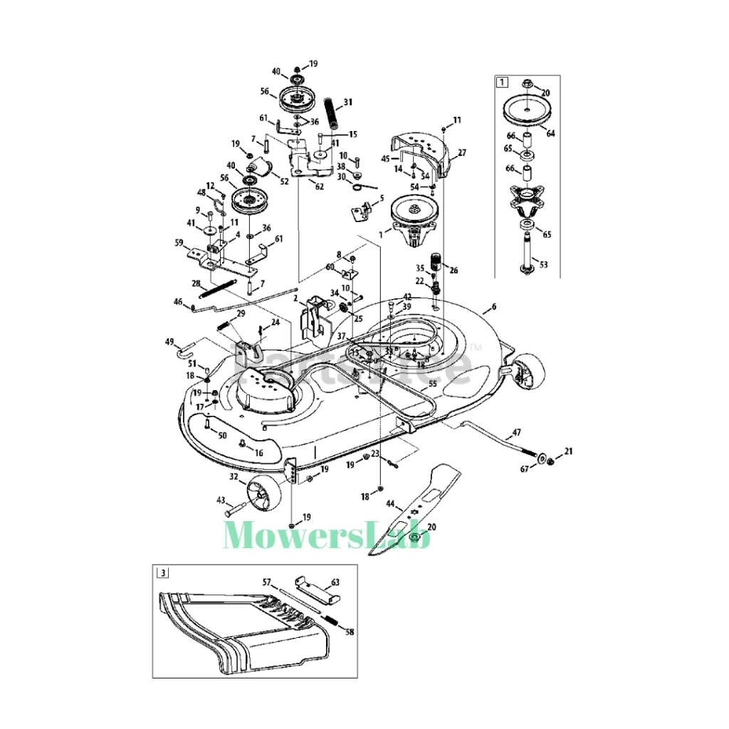
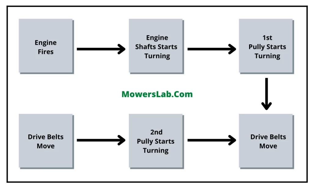
Gravely Drive Belt Diagram



![Gravely Drive Belt Diagram Guide for Easy Maintenance [Step-by-Step] 2](https://fypower.org/wp-content/uploads/2025/04/localimages/Gravely-Drive-Belt-Diagram-and-Parts-946x1024.webp "Gravely Drive Belt Diagram Guide for Easy Maintenance [Step-by-Step] 2")