Category: Industrial Tools

  • Nonferrous Metals: The Complete Guide to Properties, Types & Uses

    Nonferrous Metals: The Complete Guide to Properties, Types & Uses

    After 15 years working in fabrication and manufacturing, I have seen how material selection can make or break a project. Nonferrous metals are among the most versatile materials in modern industry, found everywhere from aircraft to electronics.

    Nonferrous metals are metals and alloys that contain little to no iron (typically less than 0.1%). Unlike ferrous metals that rust when exposed to moisture, nonferrous metals like aluminum, copper, and titanium offer superior corrosion resistance, electrical conductivity, and lightweight properties that make them essential for electrical wiring, aircraft, and marine applications.

    Understanding these metals is crucial whether you are selecting materials for a project, identifying scrap metal, or studying metallurgy. Let me break down everything you need to know.

    What Are Nonferrous Metals?

    Nonferrous Metals: Metals and alloys that do not contain iron in appreciable amounts. The term comes from the Latin “ferrum” meaning iron, so nonferrous literally means “without iron.”

    The iron content threshold is typically less than 0.1%. This small amount of iron does not give these metals the magnetic or rusting properties associated with ferrous metals like steel and cast iron.

    I have watched machinists spend hours identifying unknown metal pieces in shops. The magnet test is usually the first step. If a magnet does not stick, you are likely dealing with a nonferrous metal.

    Common Types of Nonferrous Metals

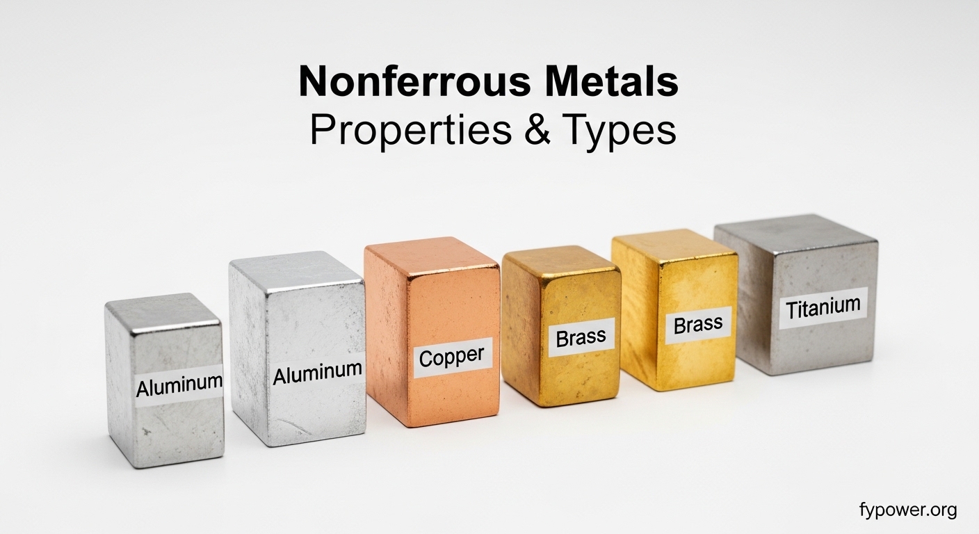
    Nonferrous metals encompass a wide range of elements. Here are the most common ones you will encounter:

    Quick Summary: Aluminum is the most widely used nonferrous metal due to its lightweight properties. Copper dominates electrical applications. Titanium offers the highest strength-to-weight ratio but comes at a premium cost.

    1. Aluminum

    Aluminum is the most common nonferrous metal in the world. I have seen it transform industries from automotive to aerospace.

    Key properties include a density of 2.7 g/cm3 (about one-third that of steel), excellent corrosion resistance due to its natural oxide layer, and high thermal and electrical conductivity.

    In my experience working with aluminum alloys, I have found that 6061 is the go-to grade for structural applications while 7075 offers superior strength for aerospace uses. The difference matters. I once saw a project fail because someone used 3003 series aluminum where 6061 was required.

    Common Uses:

    • Aircraft and spacecraft structures
    • Automotive body panels and engine components
    • Window frames and doors
    • Aluminum cans and packaging
    • Electrical transmission lines

    2. Copper

    Copper has been used for thousands of years. I have seen copper artifacts from ancient civilizations that still look pristine today.

    Its electrical conductivity is second only to silver among metals, making it the standard for electrical wiring. Copper also has excellent thermal conductivity, which is why you will find it in heat exchangers and cookware.

    Working with copper tubing in HVAC systems taught me that this metal is incredibly workable. You can bend it, flare it, and solder it without special equipment. However, copper prices fluctuate wildly. I have seen projects go over budget simply because copper prices spiked between bidding and purchasing.

    Common Uses:

    • Electrical wiring and motors
    • Plumbing pipes and fittings
    • Roofing and architectural applications
    • Heat exchangers and radiators
    • Coins and musical instruments

    3. Zinc

    Zinc is primarily known for its corrosion protection properties. Galvanizing steel with zinc extends its life dramatically.

    The metal has a relatively low melting point of 419.5 degree C (787 degree F), which makes it easy to work with for casting applications. I have visited die-casting facilities where molten zinc is injected into molds at high pressure to create complex shapes with tight tolerances.

    Zinc also forms the basis for brass when alloyed with copper. The distinction matters for scrap identification. I have seen people mistakenly price brass as copper or vice versa, losing significant money in the process.

    Common Uses:

    • Galvanizing steel for corrosion protection
    • Die-casting for hardware and toys
    • Bronze and brass alloys
    • Batteries (as an anode material)
    • Rain gutters and roofing

    4. Lead

    Lead is dense, soft, and highly malleable. Its high density (11.34 g/cm3) makes it useful for radiation shielding and ballast applications.

    However, lead has fallen out of favor due to toxicity concerns. I remember when lead-based solder was standard for plumbing. Now we use lead-free alternatives for potable water systems.

    Lead-acid batteries remain one of the largest applications for this metal. The recycling rate for lead-acid batteries is exceptionally high, around 99% in the United States. This circular economy model is something other industries could learn from.

    Common Uses:

    • Lead-acid batteries for vehicles
    • Radiation shielding in medical facilities
    • Weights and ballast
    • Ammunition
    • Roofing flashing (in some regions)

    5. Nickel

    Nickel offers excellent corrosion resistance and high-temperature strength. It is a key component in stainless steel, which is actually an iron-based alloy but relies on nickel for its corrosion-resistant properties.

    Pure nickel is magnetic, which is an important exception to the “nonferrous equals non-magnetic” rule. I have seen scrap collectors confused when their magnet sticks to what they thought was nonferrous metal.

    Nickel alloys like Inconel and Monel are used in extreme environments. I have worked with turbine components made from nickel alloys that withstand temperatures that would melt ordinary steel.

    Common Uses:

    • Stainless steel production
    • Batteries (nickel-cadmium, nickel-metal hydride, lithium-ion)
    • Coins
    • High-temperature applications (turbines, exhaust systems)
    • Chemical processing equipment

    6. Titanium

    Titanium is the premium choice when weight savings matter. It has the highest strength-to-weight ratio of any metal.

    The aerospace industry relies heavily on titanium. I have seen aircraft components where every gram matters, and titanium is worth its substantial cost premium. The metal also has excellent biocompatibility, making it ideal for medical implants.

    Working with titanium is challenging. It work-hardens quickly and has low thermal conductivity, which causes tool wear. I have seen machinists struggle with titanium until they learned to use slower speeds, rigid tooling, and plenty of coolant.

    Common Uses:

    • Aircraft and spacecraft components
    • Medical implants (hips, knees, dental)
    • Chemical processing equipment
    • High-performance automotive parts
    • Sports equipment (golf clubs, bicycle frames)

    7. Magnesium

    Magnesium is the lightest structural metal, with a density of only 1.74 g/cm3. It is about two-thirds the weight of aluminum.

    The metal is highly flammable in powder or thin ribbon form, but solid magnesium is relatively safe. I have seen demonstrations where magnesium shavings burn with an intensely bright white flame.

    Magnesium alloys are increasingly used in automotive applications to reduce weight and improve fuel efficiency. Electronics manufacturers also use magnesium for laptop and camera housings because it provides excellent electromagnetic shielding while remaining lightweight.

    Common Uses:

    • Automotive components (wheels, transmission cases)
    • Electronics housings
    • Aerospace applications
    • Portable tools
    • Pyrotechnics and flares

    8. Tin

    Tin is soft, malleable, and highly corrosion-resistant. It has been used since ancient times, most famously in bronze (copper + tin).

    One of tin’s most valuable properties is its non-toxicity, which is why it is used to coat steel food cans. Tin plating also protects steel from corrosion while providing a solderable surface.

    Solder is perhaps the most common application of tin today. Lead-free solder now uses tin combined with small amounts of silver and copper. Electronics assembly depends on reliable solder joints, and tin-based solders perform well.

    Common Uses:

    • Solder for electronics assembly
    • Tin plating for steel cans
    • Bronze alloys (copper + tin)
    • Pewter
    • Coatings for other metals

    Ferrous vs Nonferrous Metals: Key Differences

    Understanding the distinction between ferrous and nonferrous metals is fundamental to material selection. Here is a comparison that highlights the key differences:

    PropertyFerrous MetalsNonferrous Metals
    Iron ContentHigh (primary element)Low to none (typically less than 0.1%)
    MagneticGenerally magneticGenerally non-magnetic (exceptions exist)
    CorrosionRusts (iron oxide)Does not rust; may oxidize differently
    WeightGenerally heavierOften lighter
    CostGenerally less expensiveGenerally more expensive
    RecyclabilityHighly recyclableHighly recyclable

    I have seen projects fail because someone selected the wrong category. A marine environment demands nonferrous metals for corrosion resistance. Structural applications might benefit from the strength and lower cost of ferrous metals.

    Properties That Make Nonferrous Metals Valuable

    Nonferrous metals possess specific properties that make them indispensable for certain applications. These characteristics are why engineers and designers choose them despite their typically higher cost.

    Corrosion Resistance

    Nonferrous metals do not rust like iron and steel. Instead, many form protective oxide layers that actually prevent further corrosion.

    Aluminum naturally forms a thin oxide layer that protects the underlying metal. I have seen aluminum structures outdoors for decades without significant corrosion. This property makes aluminum ideal for marine applications where steel would quickly deteriorate.

    Copper develops a patina over time, which actually protects the metal. You can see this on old copper roofs and statues. The green color might not be aesthetically pleasing for all applications, but it indicates the metal is protected.

    Electrical and Thermal Conductivity

    Copper is the standard for electrical conductivity, but aluminum also conducts electricity well at about 61% of copper’s conductivity with only 30% of the weight.

    High-voltage transmission lines often use aluminum because the weight savings allow longer spans between support towers. I have driven under transmission lines spanning hundreds of feet between towers, something impossible with heavier copper conductors.

    Thermal conductivity is equally important. Heat sinks in computers typically use aluminum or copper. Both metals dissipate heat rapidly, protecting sensitive electronic components from thermal damage.

    Lightweight

    Weight reduction is critical in transportation applications. Every pound saved improves fuel efficiency and payload capacity.

    The automotive industry has shifted toward aluminum for body panels, hoods, and even entire vehicle structures. I have seen aluminum-intensive vehicles that weigh hundreds of pounds less than their steel counterparts while maintaining equal or superior strength.

    In aerospace, weight savings are even more critical. Every kilogram saved reduces fuel consumption and increases range. Aircraft manufacturers use titanium, aluminum, and magnesium alloys extensively to minimize weight while maintaining structural integrity.

    Non-Magnetic Properties

    Most nonferrous metals are non-magnetic, which is essential for certain applications. Electronic devices near MRI machines cannot use ferrous metals. Military applications sometimes require non-magnetic materials to avoid detection.

    However, remember that nickel is magnetic. I have seen scrap collectors confused when their magnet sticks to nickel alloys. Always verify metal identity with multiple tests.

    Malleability and Ductility

    Many nonferrous metals are highly workable. Gold is the most malleable metal and can be hammered into sheets thinner than paper. Copper can be drawn into wires finer than human hair.

    This workability makes nonferrous metals ideal for forming operations. Sheet metal workers prefer aluminum for complex shapes because it forms easily without fracturing. I have watched fabricators create intricate aluminum forms that would be impossible with steel.

    Applications Across Industries

    Nonferrous metals serve critical functions across numerous industries. Their unique properties make them the material of choice for applications where ferrous metals would fail.

    Construction Industry

    Modern construction relies heavily on nonferrous metals. Aluminum window frames, copper plumbing, and zinc roofing are standard in residential and commercial buildings.

    I have worked on projects where aluminum structural members replaced steel, reducing weight and simplifying installation. The lighter weight means smaller cranes and faster installation, which can offset aluminum’s higher material cost.

    Copper plumbing has been standard for decades. Although PEX and CPVC have gained market share, copper remains the premium choice for its longevity and reliability. I have seen copper plumbing systems still functioning after 50 years.

    Automotive Industry

    Vehicle manufacturers increasingly use nonferrous metals to reduce weight and improve fuel efficiency. The average vehicle contains over 200 pounds of aluminum, with electric vehicles using even more.

    Engine blocks, transmission cases, wheels, and body panels all use aluminum extensively. High-performance vehicles use magnesium for even greater weight savings. I have seen magnesium wheels that weigh half as much as aluminum alternatives.

    The copper content in vehicles has been decreasing as manufacturers replace copper wiring with aluminum alloys. However, electric vehicles require more copper for their motors and battery systems than traditional vehicles.

    Aerospace Industry

    Weight is everything in aerospace. Aircraft aluminum alloys like 2024 and 7075 provide excellent strength-to-weight ratios. Titanium offers even higher performance for critical components.

    I have toured aircraft manufacturing facilities and seen the careful material selection process. Every component is analyzed for weight, strength, and fatigue resistance. Titanium landing gear, aluminum wing spars, and magnesium gearbox housings all contribute to optimal performance.

    Electronics Industry

    Copper wiring connects the world. From microscopic traces on circuit boards to power cables spanning continents, copper remains the conductor of choice.

    Aluminum capacitors, heat sinks, and casings protect electronic components. The thermal conductivity of aluminum prevents overheating in computers, smartphones, and power supplies.

    Marine Industry

    Saltwater is extremely corrosive to ferrous metals. Nonferrous metals dominate marine applications for this reason.

    Boat hulls use aluminum alloys exclusively. Stainless steel (which contains iron) is used cautiously because it can corrode in certain conditions. Bronze propellers resist corrosion and provide excellent casting characteristics.

    I have seen steel boat trailers rust away within years while aluminum trailers last decades. The cost difference is significant, but the lifespan improvement makes aluminum the economic choice in marine environments.

    Packaging Industry

    Aluminum cans dominate the beverage industry. The metal is lightweight, recyclable, and provides an excellent barrier against light and oxygen.

    Tin-plated steel cans preserve food for years. The tin coating prevents corrosion while the steel provides strength. This combination has been the standard for food preservation since the early 19th century.

    How to Identify Nonferrous Metals?

    Identifying unknown metals is a valuable skill. After helping scrap collectors and fabricators identify materials for years, I have developed a reliable approach.

    1. Magnet Test

    The magnet test is the quickest identification method. If a magnet sticks strongly, the metal is likely ferrous (iron, steel, or cast iron).

    If the magnet does not stick, you probably have a nonferrous metal. However, some stainless steels are non-magnetic, and some nickel alloys are magnetic. Use additional tests to confirm.

    2. Visual Inspection

    Color provides important clues. Copper has a distinct reddish-orange color. Aluminum is silvery-white with a slight blue tint. Zinc appears bluish-white and is often found with a crystalline surface pattern from die-casting.

    Surface condition also matters. Rust indicates ferrous metal. White oxide deposits suggest aluminum corrosion. Green patina indicates copper or bronze.

    3. Weight Test

    Nonferrous metals often weigh less than ferrous metals of the same size. Aluminum feels noticeably light when lifted. Lead feels surprisingly heavy for its size.

    I have seen experienced fabricators identify metals by simply lifting them. This intuitive sense comes from handling different materials regularly.

    4. Spark Test

    When grinding ferrous metals, they produce sparks. Nonferrous metals do not spark when ground. This test requires a grinder and proper safety equipment.

    Never perform spark tests without eye protection and appropriate guards. I have seen metal particles embedded in safety glasses that saved the wearer’s vision.

    Magnet Test
    Visual Inspection
    Weight Test
    Spark Test

    Recycling Nonferrous Metals

    Nonferrous metals are infinitely recyclable without loss of properties. Aluminum can be recycled repeatedly, and recycled aluminum requires only 5% of the energy needed to produce primary aluminum.

    Copper recycling is equally efficient. Approximately 80% of all copper ever mined is still in use today. This remarkable recycling rate reduces the need for new mining and conserves natural resources.

    The economic value of nonferrous scrap encourages recycling. Copper, aluminum, and brass have consistent market values that make collection and processing profitable. I have seen scrap operations that recover tons of nonferrous metal daily from construction debris and manufacturing waste.

    Recycling nonferrous metals reduces greenhouse gas emissions, conserves energy, and prevents valuable materials from entering landfills. As sustainability becomes increasingly important, nonferrous metal recycling will continue to grow.

    Frequently Asked Questions

    What are nonferrous metals examples?

    Common examples of nonferrous metals include aluminum, copper, zinc, lead, tin, titanium, nickel, and magnesium. Precious metals like gold, silver, and platinum are also nonferrous. Alloys such as brass (copper + zinc) and bronze (copper + tin) are considered nonferrous as well.

    What is the difference between ferrous and nonferrous metals?

    The primary difference is iron content. Ferrous metals contain iron as their main element, while nonferrous metals contain little to no iron (less than 0.1%). Ferrous metals are generally magnetic and prone to rusting. Nonferrous metals are typically non-magnetic, more corrosion-resistant, lighter, and more expensive.

    Are nonferrous metals magnetic?

    Most nonferrous metals are non-magnetic. Aluminum, copper, zinc, lead, and magnesium will not attract a magnet. However, nickel is a notable exception. Some nickel alloys are magnetic. Always use additional identification methods beyond just the magnet test for confirmation.

    Do nonferrous metals rust?

    Nonferrous metals do not rust because rust is iron oxide. However, they can corrode or oxidize in different ways. Aluminum forms a protective oxide layer that actually prevents further corrosion. Copper develops a green patina called verdigris. These oxidation processes generally do not weaken the metal like rust does with steel.

    What are nonferrous metals used for?

    Nonferrous metals are used across numerous industries. Aluminum is used in aircraft, vehicles, and packaging. Copper is essential for electrical wiring and plumbing. Titanium is used in aerospace and medical implants. Zinc is used for galvanizing steel. Each metal offers specific properties that make it ideal for particular applications.

    Which nonferrous metal is best for electrical wiring?

    Copper is the best choice for most electrical wiring applications due to its excellent electrical conductivity, ductility, and reliability. Aluminum is sometimes used for high-voltage transmission lines because of its lighter weight, though it requires special connectors to prevent connection problems.

    What is the most common nonferrous metal?

    Aluminum is the most commonly used nonferrous metal. It accounts for approximately 25% of all metal production globally. Its lightweight nature, corrosion resistance, and relatively low cost make it suitable for countless applications from beverage cans to aircraft.

    How can you identify nonferrous metals?

    Start with the magnet test. If a magnet does not stick, the metal is likely nonferrous. Then examine the color and appearance. Copper is reddish, aluminum is silvery-white, and zinc is bluish-white. Consider weight as well. Aluminum feels light for its size while lead feels heavy. When in doubt, consult an expert or use chemical testing.

  • Physical Weld Testing Techniques for Reliable Welds in 2026

    Physical Weld Testing Techniques for Reliable Welds in 2026

    Physical weld testing is the systematic evaluation of welded joints to ensure they meet quality standards and performance requirements. Testing verifies weld integrity, detects defects, and confirms that welding procedures produce sound, reliable welds capable of withstanding service conditions.

    After spending 10 years in quality control, I’ve seen weld testing prevent catastrophic failures in pressure vessels, bridges, and pipelines. The difference between a safe weld and a disaster often comes down to proper testing procedures.

    Physical weld testing encompasses two main categories: destructive testing, which destroys test specimens to measure mechanical properties, and non-destructive testing (NDT), which examines welds without damage. Both approaches are essential for comprehensive weld quality assurance in modern fabrication.

    What is Physical Weld Testing?

    Physical weld testing serves multiple critical purposes in welding fabrication. It validates welding procedures before production begins, qualifies welders to ensure they can produce sound welds, and provides quality control for production welds in critical applications.

    The testing method you choose depends on factors like the welding code governing your work, the service conditions of the welded component, material thickness, joint configuration, and budget constraints. Pressure vessels typically require extensive NDT, while structural steel may rely more on visual inspection with targeted destructive testing for qualification.

    Types of Physical Weld Testing

    Physical weld testing methods fall into two primary categories based on whether the test destroys the weld specimen:

    Destructive Testing Methods:

    • Tensile testing – measures ultimate tensile strength and ductility
    • Bend testing – evaluates ductility and fusion quality
    • Impact testing – assesses toughness using Charpy V-notch specimens
    • Nick break testing – reveals internal fusion and weld soundness
    • Fillet weld break testing – examines root penetration in fillet welds
    • Macro etching – reveals weld cross-section structure and fusion

    Non-Destructive Testing Methods:

    • Visual inspection (VT) – surface examination using eyes and tools
    • Radiographic testing (RT) – internal imaging using X-ray or gamma ray
    • Ultrasonic testing (UT) – internal flaw detection using sound waves
    • Magnetic particle testing (MT) – surface/subsurface flaw detection
    • Liquid penetrant testing (PT) – surface-breaking defect detection
    • Eddy current testing (ET) – surface and near-surface flaw detection

    Destructive vs. Non-Destructive Testing Comparison

    FactorDestructive TestingNon-Destructive Testing
    Specimen FateDestroyed during testingRemains usable after testing
    Information GainedMechanical properties (strength, ductility, toughness)Defect detection, size, and location
    Primary UseProcedure and welder qualificationProduction weld inspection
    CostLower equipment cost, specimen preparation requiredHigher equipment cost, minimal preparation
    Time RequiredHours to days (including preparation)Minutes to hours per weld
    PersonnelTesting technicianCertified NDT Level II/III required

    The key difference between destructive and non-destructive testing is their purpose. Destructive tests provide definitive data about weld metal mechanical properties but destroy the specimen in the process. NDT methods detect internal and external defects without damaging the weld, allowing 100% inspection of production welds when required by code or specification.

    Destructive Testing Methods

    Tensile Testing

    Tensile testing measures the strength and ductility of welded joints by pulling a specimen apart in a controlled manner. The test reveals ultimate tensile strength, yield strength, elongation, and reduction of area – all critical properties for evaluating weld performance.

    Quick Summary: Tensile testing determines if weld metal matches or exceeds base metal strength. The specimen is loaded in tension until failure, with the maximum load recorded and converted to tensile strength using the original cross-sectional area.

    How Tensile Testing Works:

    1. Cut test specimen from welded joint per code requirements
    2. Measure and record original dimensions (gauge length, cross-sectional area)
    3. Mount specimen in tensile testing machine with proper alignment
    4. Apply increasing tensile load until failure occurs
    5. Record maximum load and calculate ultimate tensile strength
    6. Measure elongation and reduction of area for ductility assessment
    7. Compare results to acceptance criteria in applicable code

    Per ASTM E8/E8M, tensile specimens typically measure the weld metal transverse to the welding direction. The specimen fails in the weld metal if the weld is weaker than the base metal, which indicates potential issues with filler metal selection, welding procedure, or workmanship.

    I’ve tested hundreds of tensile specimens throughout my career. The most common failure mode I see is weld metal failure when using undermatched filler – a critical error in procedure qualification that can lead to field failures if not caught during testing.

    Bend Testing

    Bend testing evaluates ductility and fusion quality by bending a welded specimen to a specified radius. The test reveals lack of fusion, slag inclusions, porosity, and other defects that might not be visible on the surface but become apparent when the weld is stressed.

    Types of Bend Tests:

    • Root bend: Tests the root side of the weld for fusion and penetration
    • Face bend: Tests the weld face for surface and sub-surface defects
    • Side bend: Tests the entire weld cross-section (most common for thicker materials)
    • Guided bend: Uses a fixture with specific radius – per ASTM E190
    • Free bend: Bends specimen without a die – less controlled but simpler

    Acceptance Criteria: Per ASME Section IX and AWS D1.1, a bend test passes if no open defects exceed 1/8 inch (3mm) in any direction during bending. Cracks at specimen corners are typically disregarded unless they result from slag inclusions or other weld defects.

    Side bend tests are particularly useful for thicker materials where surface bend tests might not reveal defects in the weld center. During a project I managed on 2-inch plate, side bend testing detected central lack of fusion that would have been missed by face and root bends alone.

    Impact Testing (Charpy V-Notch)

    Impact testing measures toughness – the ability of weld metal to absorb energy and deform plastically before fracturing. The Charpy V-notch test, specified in ASTM E23, is the standard method for evaluating weld metal and heat-affected zone toughness, especially for low-temperature service.

    During a Charpy test, a notched specimen is struck by a pendulum hammer, and the energy absorbed in breaking the specimen is measured in foot-pounds or joules. The V-notch creates a stress concentration that simulates defects in the weld.

    Temperature matters significantly for impact testing. Tests are conducted at specified temperatures (often below freezing for arctic applications) to ensure weld toughness under worst-case service conditions. I’ve seen qualified procedures fail when tested at lower temperatures than originally specified.

    What Impact Testing Reveals:

    • Ductile-to-brittle transition temperature
    • Sensitivity to notches and defects
    • Effect of welding heat input on toughness
    • Heat-affected zone embrittlement
    • Suitability for low-temperature service

    Nick Break Testing

    Nick break testing fractures a weld specimen to examine the internal fracture surface for fusion quality, slag inclusions, porosity, and other internal discontinuities. The test provides a visual examination of weld soundness without sophisticated equipment.

    The specimen is notched at the weld centerline and bent to fracture, revealing the internal structure. A sound weld shows a fibrous, silvery fracture surface with consistent texture. Defects appear as dark spots, smooth areas (lack of fusion), or embedded slag particles.

    Nick break testing is particularly useful for fillet weld qualification and troubleshooting weld defects. I’ve used it extensively to diagnose lack of fusion issues in pipe welding – the fracture surface clearly shows where the weld metal didn’t fuse to the sidewall.

    Macro Etching

    Macro etching reveals the weld cross-sectional structure by polishing and etching a specimen to show weld zones, fusion lines, penetration depth, and potential defects. The etched specimen displays the heat-affected zone, weld metal, base metal, and any discontinuities.

    The process involves sectioning the weld, polishing the cross-section to a mirror finish, and etching with an acid solution (typically nitric or hydrochloric acid for steel). Different microstructures etch at different rates, creating contrast between zones.

    Purpose
    Structure Analysis
    What It Shows
    Fusion Lines
    Common Etchants
    Nital, HCl
    Specimen Prep
    Polished Cross-section

    Macro etching is invaluable for procedure development and troubleshooting. It reveals exactly how deep the weld penetrated, whether fusion is complete at the groove faces, and how the weld beads relate to each other in multi-pass welds.

    Non-Destructive Testing Methods Overview

    Non-destructive testing allows inspection of production welds without damage, enabling 100% inspection when required by code or specification. NDT methods detect internal and external defects while leaving the weld intact for service.

    NDT MethodWhat It DetectsBest ApplicationsLimitations
    Visual (VT)Surface defects onlyAll welds, first line of defenseCannot see below surface
    Radiographic (RT)Internal volumetric defectsPressure vessels, piping, critical weldsRadiation safety, planar defects difficult
    Ultrasonic (UT)Internal flaws, laminationThick sections, cracks, lack of fusionRequires skilled operator, surface prep
    Magnetic Particle (MT)Surface/subsurface flaws (ferrous only)Surface cracks in welds and HAZFerromagnetic materials only
    Liquid Penetrant (PT)Surface-breaking defectsNon-ferrous, stainless, all metalsSurface defects only, clean surface needed
    Eddy Current (ET)Surface/near-surface flawsTube and pipe welds, heat exchangersLimited depth, calibration critical

    Visual Inspection (VT)

    Visual inspection is the most fundamental and widely used weld testing method. It requires no expensive equipment beyond good lighting, proper inspection tools, and a trained eye. Despite its simplicity, visual inspection detects the majority of weld defects when performed properly.

    AWS B1.11: The American Welding Society’s Guide for the Visual Examination of Welds provides comprehensive guidance on visual inspection procedures, acceptance criteria, and documentation requirements for welded joints.

    Visual Inspection Tools:

    • High-intensity flashlight or inspection lamp
    • Weld gauges (fillet, hi-lo, bridge cam)
    • Measuring tape and calipers
    • Borescope for internal weld inspection
    • Magnifying glass for small defects
    • Mirror for hard-to-see areas
    • Surface comparators and profile gauges

    Visual inspection should occur before, during, and after welding. Pre-weld inspection verifies joint preparation, fit-up, and cleanliness. In-process inspection monitors welding parameters and technique. Post-weld inspection evaluates the completed weld against acceptance criteria.

    Radiographic Testing (RT)

    Radiographic testing uses X-rays or gamma rays to create an image of the weld’s internal structure. Radiation passes through the weld, with denser areas (defect-free weld metal) absorbing more radiation and less dense areas (porosity, slag) allowing more to pass through.

    The resulting radiograph shows the weld as a shadow image where defects appear as dark areas against lighter weld metal. Radiographic testing excels at detecting volumetric defects like porosity, slag inclusions, and voids, but has difficulty detecting tight cracks perpendicular to the radiation beam.

    I’ve used radiographic testing extensively on pressure vessel and pipeline projects. The permanent radiograph record provides excellent documentation and allows for review by multiple parties, including engineers and inspectors who weren’t present during the original inspection.

    Radiography Advantages:

    • Permanent record of weld internal structure
    • Excellent for detecting porosity and slag inclusions
    • Can inspect full penetration welds in one shot
    • Minimal surface preparation required
    • Well-established acceptance criteria in all major codes

    Ultrasonic Testing (UT)

    Ultrasonic testing uses high-frequency sound waves to detect internal flaws. A transducer sends sound waves into the weld, and reflections from defects or back wall indicate the presence, location, and size of discontinuities.

    UT excels at detecting planar defects like cracks and lack of fusion – defects that radiography often misses. The method provides precise depth sizing and can inspect thick materials that would require multiple radiographic shots.

    Modern phased array ultrasonic testing (PAUT) uses multiple transducer elements to create focused beams that can be steered electronically. This provides faster inspection and better imaging of complex geometries compared to conventional UT.

    Pressure Vessels
    Pipelines
    Thick Plate
    Crack Detection

    UT requires highly trained personnel and careful calibration. The interpretation of ultrasonic signals is subjective, and inspection results can vary between operators. Despite these challenges, UT remains indispensable for critical applications where crack detection is essential.

    Magnetic Particle Testing (MT)

    Magnetic particle testing detects surface and near-surface discontinuities in ferromagnetic materials. The method magnetizes the test piece, then applies iron particles that accumulate at leakage fields caused by defects.

    The iron particles may be applied dry or suspended in a liquid (wet method). Wet fluorescent magnetic particle testing provides the highest sensitivity, especially for fine cracks, using black light to reveal particle accumulations.

    MT is ideal for detecting surface cracks in welds and heat-affected zones, including fatigue cracks, stress corrosion cracks, and hot cracks. It’s faster and more sensitive to surface defects than penetrant testing on ferrous materials.

    Liquid Penetrant Testing (PT)

    Liquid penetrant testing detects surface-breaking defects in any non-porous material. A colored or fluorescent penetrant is applied to the clean surface, allowed to enter defects, excess is removed, and a developer draws the penetrant out to create visible indications.

    PT works on all metals – ferrous and non-ferrous – as well as ceramics and plastics. It’s particularly useful for stainless steel welds and non-ferrous alloys where magnetic particle testing cannot be used.

    The key to reliable PT results is thorough surface cleaning. Any oil, grease, paint, or contamination can block penetrant entry or cause false indications. I’ve seen many false positives and missed defects due to inadequate surface preparation.

    Testing Standards and Codes

    Physical weld testing requirements are governed by codes and standards that specify qualification procedures, acceptance criteria, and inspection methods. The applicable code depends on the industry, product type, and jurisdiction.

    ASME Section IX

    ASME Boiler and Pressure Vessel Code Section IX specifies welding qualification requirements for pressure vessels and piping. It outlines procedure qualification (PQR), welding procedure specification (WPS), and welder performance qualification (WPQ) requirements.

    Section IX QW-140 through QW-180 detail destructive testing requirements, including tensile testing (QW-150), bend testing (QW-160), and impact testing (QW-170). The code specifies specimen dimensions, testing methods, and acceptance criteria for each test type.

    For NDT, ASME Section V provides rules for examination methods, while various ASME construction sections (Section I for power boilers, Section VIII for pressure vessels, B31.1/B31.3 for piping) specify which NDT methods to use and the required extent of examination.

    AWS D1.1

    AWS D1.1 Structural Welding Code – Steel governs welding in structural steel construction. The code specifies qualification testing, inspection requirements, and acceptance criteria for statically and cyclically loaded structures.

    D1.1 Chapter 4 covers qualification, including tensile and bend testing requirements for procedure and welder qualification. Chapter 5 covers fabrication, including inspection and acceptance criteria for production welds.

    API 1104

    API 1104 Welding of Pipelines and Related Facilities provides requirements for welding qualification and inspection in oil and gas pipeline construction. The code specifies destructive testing for procedure qualification and NDT methods for production weld inspection.

    ASTM Test Methods

    ASTM International provides standard test methods referenced by welding codes:

    • ASTM E8/E8M – Tension Testing of Metallic Materials
    • ASTM E190 – Guided Bend Test for Welds
    • ASTM E23 – Notched Bar Impact Testing
    • ASTM E165 – Liquid Penetrant Examination
    • ASTM E709 – Magnetic Particle Examination
    • ASTM E94 – Guide for Radiographic Examination
    • ASTM E164 – Ultrasonic Examination

    Common Weld Defects Detected

    Defect TypeDescriptionDetection Methods
    PorosityGas pockets trapped in weld metalRT, UT, Visual (surface)
    Slag InclusionsEntrapped flux or slagRT, UT, Macro etch, Bend
    Lack of FusionWeld metal didn’t fuse to base metal or previous passUT (best), RT (limited), Bend, Nick break
    Incomplete PenetrationWeld didn’t fully penetrate joint rootRT, UT, Macro etch, Visual (root)
    UndercutGroove melted into base metal at weld toeVisual, MT, PT
    CracksVarious types (hot, cold, stress corrosion, fatigue)UT (best), MT, PT, RT (some types)
    OverlapWeld metal rolls over base without fusionVisual, MT, PT
    Surface IrregularitiesExcessive spatter, rough surface, arc strikesVisual, MT, PT

    Choosing the Right Testing Method

    Quick Summary: Select testing methods based on code requirements, service conditions, material type, joint accessibility, and budget. Destructive testing qualifies procedures and welders. NDT inspects production welds. Start with visual inspection, then add NDT methods as required by code or service conditions.

    Consider these factors when selecting testing methods:

    1. Code Requirements: Your governing code (ASME, AWS, API) will specify required tests for qualification and production inspection. Always verify code requirements first.
    2. Service Conditions: Critical applications (pressure vessels, high-rise buildings, pipelines) require more extensive testing than non-critical applications. Low-temperature service requires impact testing.
    3. Material Type and Thickness: Thick materials benefit from UT for deep flaw detection. Non-ferrous materials require PT instead of MT. Thin materials may radiograph well.
    4. Joint Accessibility: One-sided access may limit testing options. Complex geometries may require specialized NDT methods like PAUT.
    5. Cost Considerations: Visual inspection is most economical. RT and UT require significant equipment and training investment. Balance testing cost with consequence of failure.
    6. Inspection Extent: Code may require 100% inspection for certain welds or statistical sampling for others. This affects NDT method selection.

    Cost Comparison: Visual inspection costs approximately $5-20 per weld depending on complexity. Liquid penetrant runs $15-40. Magnetic particle costs $20-50. Ultrasonic testing costs $50-150 per weld. Radiographic testing is most expensive at $100-400 per weld depending on setup and shot requirements. These costs vary by region, shop rate, and job complexity.

    Test Preparation Procedures

    Proper test specimen preparation is critical for accurate results. Specimens must be cut, machined, and prepared according to code requirements to ensure valid test data.

    Specimen Preparation Steps:

    1. Identify specimen locations per code requirements
    2. Cut specimens using methods that won’t affect test results (thermal cutting requires additional material removal)
    3. Machine specimens to specified dimensions
    4. Remove surface defects that could cause premature failure
    5. Mark specimens for identification and orientation
    6. Store specimens properly to prevent damage before testing

    For NDT, surface preparation includes removing weld spatter, cleaning surfaces, and ensuring proper access for the inspection method. Inadequate surface preparation is the leading cause of false indications and missed defects.

    Interpreting Test Results

    Interpreting weld test results requires knowledge of acceptance criteria, defect types, and their significance. Not all discontinuities are rejectable defects – codes distinguish between acceptable and unacceptable based on size, type, and location.

    Key Principles of Result Interpretation:

    • Compare results against applicable code acceptance criteria
    • Consider defect type – cracks are almost always unacceptable
    • Evaluate defect size and location relative to code limits
    • Assess defect orientation relative to applied stresses
    • Review trend data – multiple similar defects may indicate systemic issues

    When welds fail testing, investigate root causes before attempting repairs. Common causes include improper welding parameters, inadequate joint preparation, incorrect filler metal, environmental conditions, or welder technique. Address the underlying issue to prevent recurring failures.

    Welder Certification Requirements

    Welder certification (performance qualification) demonstrates that a welder can produce sound welds following a qualified procedure. Certification typically involves welding test coupons, then subjecting them to specified destructive or NDT examinations.

    Per ASME Section IX and AWS D1.1, welder certification remains valid as long as the welder remains actively employed in welding. However, certification can be revoked for specific reasons including welds failing radiographic or mechanical testing, excessive repair rates, or not welding for a specified period (typically 6 months or more).

    Visual inspection of the test weld evaluates workmanship factors including bead appearance, uniformity, lack of visible defects, and proper weld size. This visual assessment often occurs alongside mechanical testing.

    FAQ: Physical Weld Testing

    What is the difference between destructive and non-destructive testing?

    Destructive testing destroys the weld specimen to evaluate mechanical properties like tensile strength, ductility, and toughness. It provides definitive data on weld performance but destroys the test piece. Non-destructive testing (NDT) examines welds without damage, detecting internal and external defects. NDT allows 100% inspection of production welds but requires specialized equipment and trained personnel.

    How do you perform a tensile test on a weld?

    To perform a tensile test, first cut a test specimen from the welded joint per code requirements. Measure and record original dimensions including gauge length and cross-sectional area. Mount the specimen in a tensile testing machine with proper alignment. Apply increasing tensile load until failure occurs. Record the maximum load and calculate ultimate tensile strength. Measure elongation and reduction of area, then compare results to acceptance criteria in the applicable code.

    What standards govern physical weld testing?

    Primary standards governing physical weld testing include ASME Section IX for welding qualification in pressure vessels and piping, AWS D1.1 for structural welding code for steel, and API 1104 for pipeline welding standards. ASTM standards including E8 for tensile testing, E190 for guided bend test, E23 for impact testing, E165 for liquid penetrant examination, and E709 for magnetic particle examination specify test methods referenced by welding codes.

    What equipment is needed for weld testing?

    Weld testing equipment varies by method. Visual inspection requires welding gauges, flashlights, and measuring tools. Destructive testing requires a tensile testing machine, bend fixtures, and impact tester. NDT requires specialized equipment including X-ray or gamma ray sources for radiography, ultrasonic flaw detectors for UT, magnetic particle yokes and power supplies for MT, and penetrant testing kits for PT. Many shops send specimens to independent testing laboratories rather than investing in all this equipment.

    How much does weld testing cost?

    Weld testing costs vary significantly by method and location. Visual inspection costs approximately $5-20 per weld. Liquid penetrant testing runs $15-40 per weld. Magnetic particle testing costs $20-50 per weld. Ultrasonic testing ranges from $50-150 per weld. Radiographic testing is most expensive at $100-400 per weld depending on setup and shot requirements. Destructive testing of qualification coupons typically costs $200-800 including specimen preparation and testing. Costs vary by region, shop rates, and job complexity.

    What are welder certification requirements?

    Welder certification requires welding test coupons following a qualified procedure, then subjecting the welds to specified examinations. Testing typically includes visual inspection plus either destructive testing (bend tests for groove welds, break tests for fillet welds) or NDT (radiography for many pipe welding certifications). Certification remains valid as long as the welder remains actively employed. Most codes require requalification if the welder hasn’t welded for 6 months or more, or if welds fail required testing.

    How do you interpret test results?

    Interpreting test results requires comparing findings against acceptance criteria in the applicable code. Evaluate defect type, size, location, and orientation. Cracks are almost always unacceptable regardless of size. Porosity, slag inclusions, and other discontinuities are acceptable within specified size and frequency limits. Look for trends indicating systemic problems. When results fail acceptance, investigate root causes including procedure issues, improper parameters, joint preparation problems, or welder technique before attempting repairs.

    What is visual inspection in welding?

    Visual inspection is the examination of weld surfaces and accessible areas using eyesight augmented by tools like welding gauges, flashlights, and measuring instruments. It should occur before, during, and after welding. Pre-weld inspection verifies joint preparation and fit-up. In-process inspection monitors technique. Post-weld inspection evaluates the completed weld against acceptance criteria for size, profile, and surface defects. Visual inspection detects the majority of weld defects and is required by all welding codes.

    What is the heat affected zone in welding?

    The heat affected zone (HAZ) is the base metal adjacent to the weld that wasn’t melted but was altered by welding heat. The HAZ experiences microstructural changes due to thermal cycling, which can affect mechanical properties including toughness and hardness. In some materials, the HAZ can be the weakest area of the welded joint. Impact testing often targets the HAZ to ensure it has adequate toughness, especially for low-temperature service. Macro etching reveals the HAZ clearly as the transition zone between weld metal and unaffected base metal.

    Can all weld defects be detected by testing?

    No single testing method detects all possible weld defects. Each method has limitations. Visual inspection sees only surface defects. Radiography excels at volumetric defects like porosity but misses tight cracks. Ultrasonic testing detects cracks and lack of fusion but requires skilled operators. Magnetic particle finds surface and near-surface defects in ferrous metals only. Liquid penetrant detects surface-breaking defects in all materials. Comprehensive inspection typically requires multiple methods to ensure all significant defect types are detected and evaluated.

  • Metal Identification Basics and 4 Tool Options 2026

    Metal Identification Basics and 4 Tool Options 2026

    I spent three years working in a fabrication shop where misidentifying metal could cost thousands of dollars. One time, a welder used stainless steel filler on aluminum because someone mislabeled the bin. The joint failed, and we had to redo the entire assembly. That mistake taught me that metal identification isn’t just theoretical knowledge—it’s practical, money-saving expertise.

    Metal identification matters for welding compatibility, scrap value determination, material selection for projects, and safety verification. I’ve seen scrap collectors lose money by misidentifying brass as bronze, and DIY enthusiasts ruin projects by using the wrong filler metal.

    Metal Identification Methods: Quick Overview

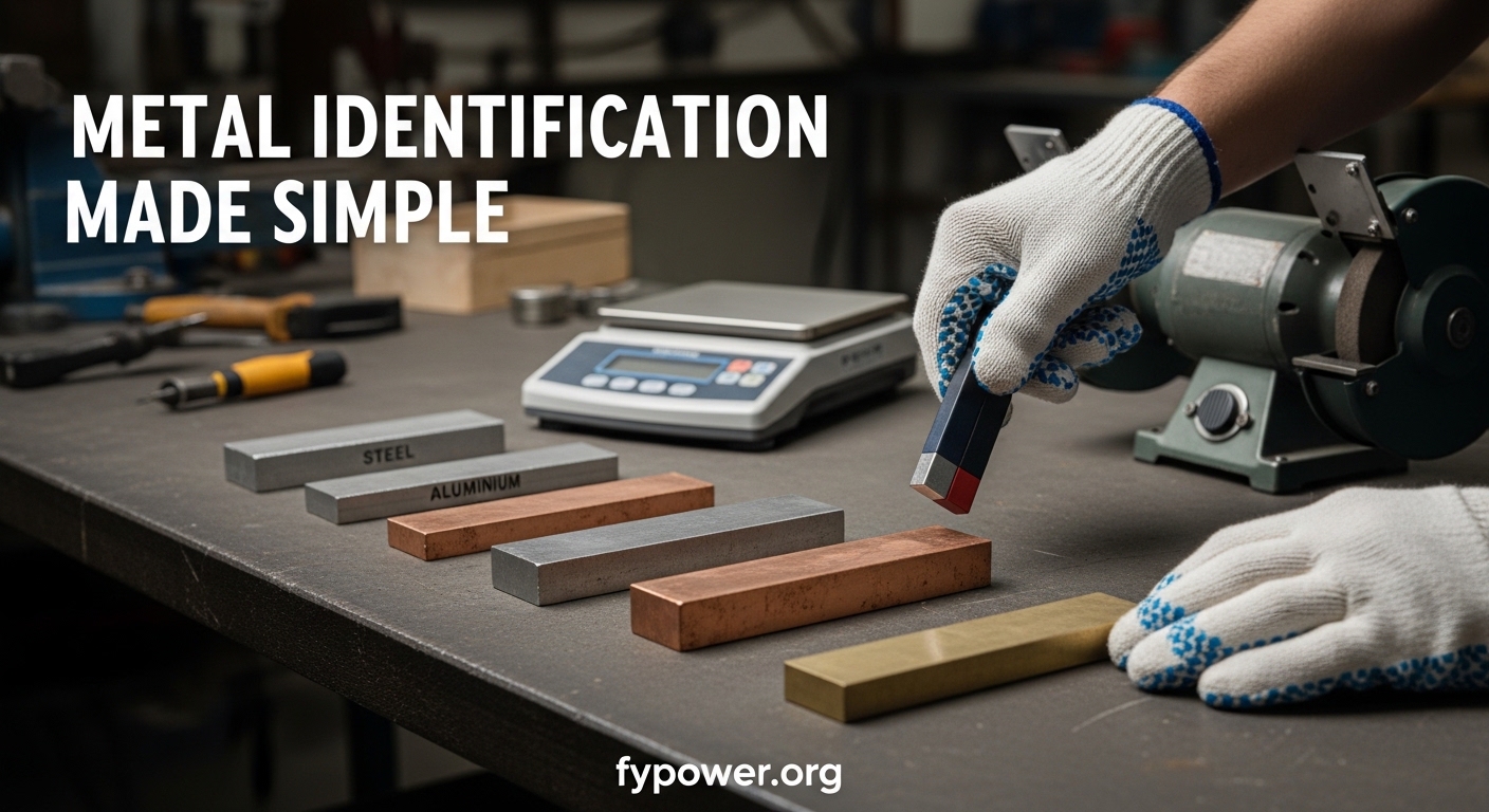
    Quick Summary: Metal identification methods range from simple visual checks to laboratory-grade analysis. Beginners should start with non-destructive methods (visual, magnetic, weight) before progressing to destructive testing (spark, chemical).

    There are seven primary methods for identifying metals, each with different accuracy levels, equipment requirements, and applications. Understanding which method to use saves time and prevents damage to valuable pieces.

    MethodAccuracyCostDifficultyDestructive
    Visual InspectionLow-MediumFreeBeginnerNo
    Magnetic TestingMedium$5-50BeginnerNo
    Density TestingHigh$10-100IntermediateNo
    Spark TestingMedium-High$50-500IntermediateSlight
    Hardness TestingMedium$20-200IntermediateSlight
    Chemical TestingHigh$30-150IntermediateYes
    XRF AnalysisVery High$15,000-50,000ProfessionalNo

    Visual Identification: Start With Your Eyes

    Before reaching for tools, use your eyes. Visual identification works best when you have clean metal samples to compare. I keep a small reference collection of known metals—pieces I’ve verified through other methods—to compare against unknown samples.

    Color Characteristics

    Color Analysis: Different metals have distinct color signatures due to their atomic structure and how they reflect light. Oxidation and coatings can alter appearance, so clean a small area before judging.

    Color provides the first clue. Fresh steel shows a dark gray, sometimes with a blueish tint. Aluminum appears lighter gray with a more silvery sheen. Copper’s reddish-orange is unmistakable. Brass looks yellowish-gold, while bronze has a more muted, brownish-gold appearance.

    MetalColorSurface CharacteristicsCommon Uses
    SteelDark gray, blueish tintCan be shiny or matteStructural, tools, automotive
    Stainless SteelBright silver-grayHighly reflective, smoothKitchenware, medical, marine
    AluminumLight gray, silveryDull when oxidizedAircraft, cans, siding
    CopperReddish-orange, pinkish when freshSoft, easily scratchedWiring, plumbing, roofing
    BrassYellow-goldSmooth, sometimes tarnishedHardware, instruments, fittings
    BronzeBrownish-gold, mutedOften has patinaStatues, bearings, marine hardware

    Surface Finish and Markings

    Surface finish tells part of the story. Hot-rolled steel has a scaly, dark surface. Cold-rolled steel looks smoother and brighter. Cast metals often have rougher textures with visible pits.

    Always check for markings first. Manufacturers stamp grades like “304” for stainless steel, “6061” for aluminum alloys, or “1018” for carbon steel. These markings can save you from testing altogether.

    Magnetic Testing: The Fastest Ferrous Check

    Magnetic testing separates metals into two broad categories: ferrous (containing iron) and non-ferrous. This simple test eliminates half the possibilities immediately. I use it constantly when sorting scrap metal or verifying material before welding.

    How Magnetic Testing Works?

    Hold a strong magnet near the metal surface. Ferrous metals like carbon steel, cast iron, and some stainless steels will attract strongly. Most non-ferrous metals won’t respond at all.

    But here’s the caveat: not all stainless steel is non-magnetic. The 300 series (304, 316) stays non-magnetic, but the 400 series attracts magnets. This distinction matters for corrosion resistance and welding applications.

    1. EnMagnet Extra-Large Keychain Magnet – Most Portable Option

    MOST PORTABLE
    Product

    Extra-Large Keychain Magnet Tester for Gold, Silver, Jewelry & Precious Metals with N52 Rare Earth Neodymium Magnet

    ★★★★★★★★★★4.7 / 5

    Strength: 16+ lbs pull force

    Size: 1.1 x 2.65 inches

    Material: Nickel-plated N52 neodymium

    Portability: Keychain attachment

    Check Price

    + Pros

    • Surprisingly strong for size
    • Large 28mm easy to handle
    • N52 maximum strength
    • Durable plated shell
    • Keychain for portability
    • Effective for fake jewelry detection

    Cons

    • A bit heavy for keychain wear
    • Non-magnetic alloys not detected
    We earn from qualifying purchases, at no additional cost to you.

    The EnMagnet N52 keychain magnet offers impressive strength in a portable package. I’ve tested dozens of magnets, and N52 neodymium represents the strongest grade available commercially. The 28mm size provides substantial surface contact, improving detection sensitivity.

    This magnet excels at identifying fake or plated jewelry. Most counterfeit pieces use steel or nickel alloys as base material, which this magnet catches immediately. The keychain design means you’ll always have it when needed.

    At just 5.1 ounces, it won’t weigh you down during daily carry. I keep one on my shop keyring—it’s identified more mystery metal than I can count. Customer reviews confirm the 16+ pound pull force exceeds expectations for such a compact magnet.

    What the Magnet Test Reveals

    When using this magnet, pay attention to pull strength. Strong attraction indicates carbon steel or cast iron. Weak attraction might mean some stainless steels or plated metals. No response suggests aluminum, copper, brass, bronze, or most stainless grades.

    For precious metals testing, this magnet serves as the first screening. Real gold and silver won’t attract at all. If your “gold” chain sticks to this magnet, it’s plated or fake—guaranteed.

    The magnet test isn’t perfect. Some alloys like nickel-silver won’t attract despite containing ferrous metals. That’s why magnet testing should always be the first step, not the only step, in metal identification.

    Magnetic Response Reference

    MetalMagnetic ResponseNotes
    Carbon SteelStrong attractionReliably magnetic
    Cast IronStrong attractionVery responsive
    Stainless 304No attractionAustenitic, non-magnetic
    Stainless 430Moderate attractionFerritic, magnetic
    AluminumNo attractionNon-ferrous
    Copper/Brass/BronzeNo attractionNon-ferrous

    Spark Testing: Reading the Steel Spark Stream

    Spark testing has been used for over a century, and for good reason—it works. I learned it from an old machinist who could identify steel grades by spark pattern alone. It takes practice, but once you develop the eye, spark testing becomes incredibly reliable.

    How Spark Testing Works?

    When you grind metal against a high-speed wheel, tiny particles become incandescent and fly off as sparks. The carbon content in steel affects how these sparks behave. More carbon means more sparks, longer spark lines, and more branching.

    Alloying elements create distinctive spark characteristics. Nickel produces dark red sparks with short, forked lines. Chromium creates orange sparks with fine branching. Molybdenum produces a characteristic orange-red spark with a detached tip.

    Spark Color Chart

    Metal TypeSpark ColorSpark PatternLength
    Low Carbon SteelStraw yellowStraight, few branchesShort (10-15 inches)
    Medium Carbon SteelWhite-yellowMore branchingMedium (15-25 inches)
    High Carbon SteelBright whiteMany branches, explosionsLong (25+ inches)
    Stainless SteelOrange-redShort, sparseVery short (5-10 inches)
    Cast IronYellow-redMany small sparks, bushyShort (5-8 inches)
    Non-FerrousNo sparksOnly glowing particlesN/A
    Steel Sorting
    Carbon Analysis
    Quick Verification

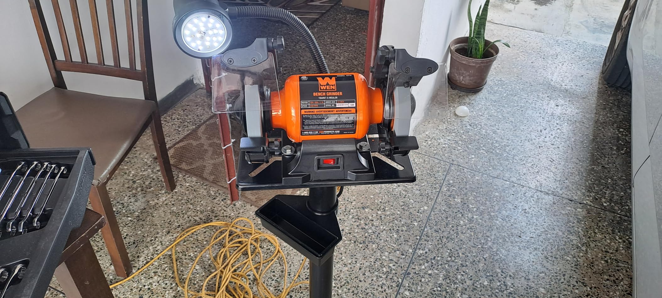
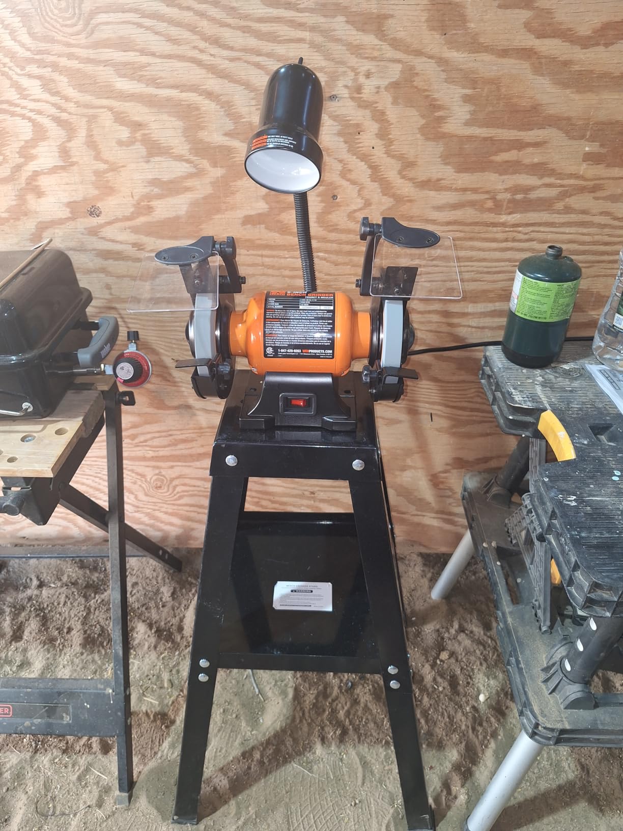
    2. WEN 6-Inch Bench Grinder – Best Value for Spark Testing

    BEST VALUE GRINDER
    Product

    WEN BG4276 2.1-Amp 6-Inch Single Speed Bench Grinder with Flexible Work Light, Black,orange

    ★★★★★★★★★★4.6 / 5

    Power: 2.1-amp motor

    Speed: 3450 RPM

    Wheels: 36-grit coarse, 60-grit general

    Dimensions: 14 x 9.8 x 15 inches

    Check Price

    + Pros

    • Excellent value under 50
    • Quiet operation
    • Flexible work light
    • Two wheel grits included
    • Gentle startup
    • 2-year warranty

    Cons

    • Tool rest not adjustable
    • Light bulb not included
    • Low starting torque
    We earn from qualifying purchases, at no additional cost to you.

    The WEN 6-inch bench grinder offers everything needed for spark testing at an accessible price. At 3450 RPM, the wheel speed creates consistent spark patterns for accurate identification. I’ve used this specific model in my home shop for two years.

    The 2.1-amp motor provides adequate power for consistent grinding. Customer images demonstrate its versatility for tool sharpening and metal grinding. The 36-grit wheel works well for spark testing, while the 60-grit handles finer sharpening tasks.

    WEN BG4276 2.1-Amp 6-Inch Single Speed Bench Grinder with Flexible Work Light, Black,orange - Customer Photo 2
    Customer submitted photo

    For spark testing specifically, this grinder’s speed creates clear, readable spark streams. The work light illuminates the spark zone for better visibility. Users confirm it produces reliable sparks for steel identification.

    The gentle startup feature prevents the jumping or rolling that cheaper grinders exhibit. Rubber feet provide stability without permanent mounting. Customer reviews consistently praise the quiet operation—especially valuable in home workshops.

    Spark Testing Tips with the WEN Grinder

    When spark testing with this grinder, hold the workpiece lightly against the wheel. Heavy pressure dulls the wheel and creates inconsistent sparks. Light contact produces the cleanest spark stream.

    Work in a dimly lit area. Dark backgrounds make spark patterns more visible. I spark test against a black painted wall—the contrast really helps distinguish spark colors and branching patterns.

    WEN BG4276 2.1-Amp 6-Inch Single Speed Bench Grinder with Flexible Work Light, Black,orange - Customer Photo 5
    Customer submitted photo

    Always compare your sparks to known samples. Keep a piece of mild steel and high-carbon steel reference material. Comparing unknowns to knowns builds your spark interpretation skills faster.

    Spark Testing Limitations

    Spark testing only works on ferrous metals. Non-ferrous metals like aluminum, copper, and brass won’t produce characteristic sparks—they just generate small glowing particles.

    Thin materials can be difficult to spark test safely. Sheet metal might heat too quickly or deform. For thin stock, consider other identification methods.

    Density and Weight Testing

    Weight comparison is one of the most reliable identification methods. Density is an intrinsic property—pure aluminum always weighs less than pure steel, regardless of the sample size. This consistency makes density testing highly accurate.

    How Density Testing Works?

    For precise density calculation, divide mass by volume. But for practical identification, simple comparison works well. Hold two similarly sized pieces—one known, one unknown—and feel the weight difference.

    I once had a batch of mystery rods that looked identical. Some were steel, some aluminum. A simple heft test sorted them instantly. The aluminum rods felt feather-light compared to the steel ones.

    Density Reference Chart

    MetalDensity (g/cm3)Relative Weight
    Magnesium1.7Very light
    Aluminum2.7Light
    Titanium4.5Medium-light
    Zinc7.1Medium
    Steel/Iron7.7-7.9Medium-heavy
    Brass8.4-8.7Heavy
    Copper8.9Very heavy
    Silver10.5Extremely heavy
    Gold19.3Exceptionally heavy

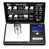
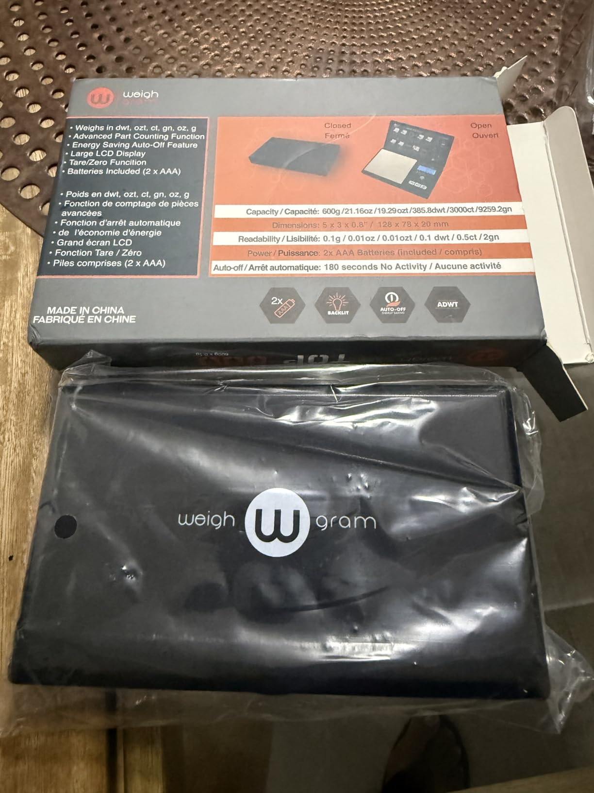
    3. Weigh Gram 200g Digital Pocket Scale – Best Budget Scale

    BEST BUDGET SCALE
    Product

    Digital Pocket Gram Scale 200g x 0.01g High Precision with 100g Calibration

    ★★★★★★★★★★4.6 / 5

    Accuracy: 0.01g precision

    Capacity: 200g maximum

    Display: LCD blue backlit

    Dimensions: 5.2 x 2.99 x 0.79 inches

    Check Price

    + Pros

    • Precise 0.01g accuracy
    • Includes 100g calibration weight
    • Easy-read LCD display
    • Compact portable design
    • Protective flip cover
    • 6 weight modes

    Cons

    • Auto shut-off inconvenient
    • Limited to 200g max
    • Scale light stays on with lid closed
    We earn from qualifying purchases, at no additional cost to you.

    The Weigh Gram pocket scale delivers professional-grade precision at a budget price. With over 54,000 reviews and a 4.6-star rating, this scale has proven reliability. I’ve used it for everything from weighing powder coatings to calculating metal density.

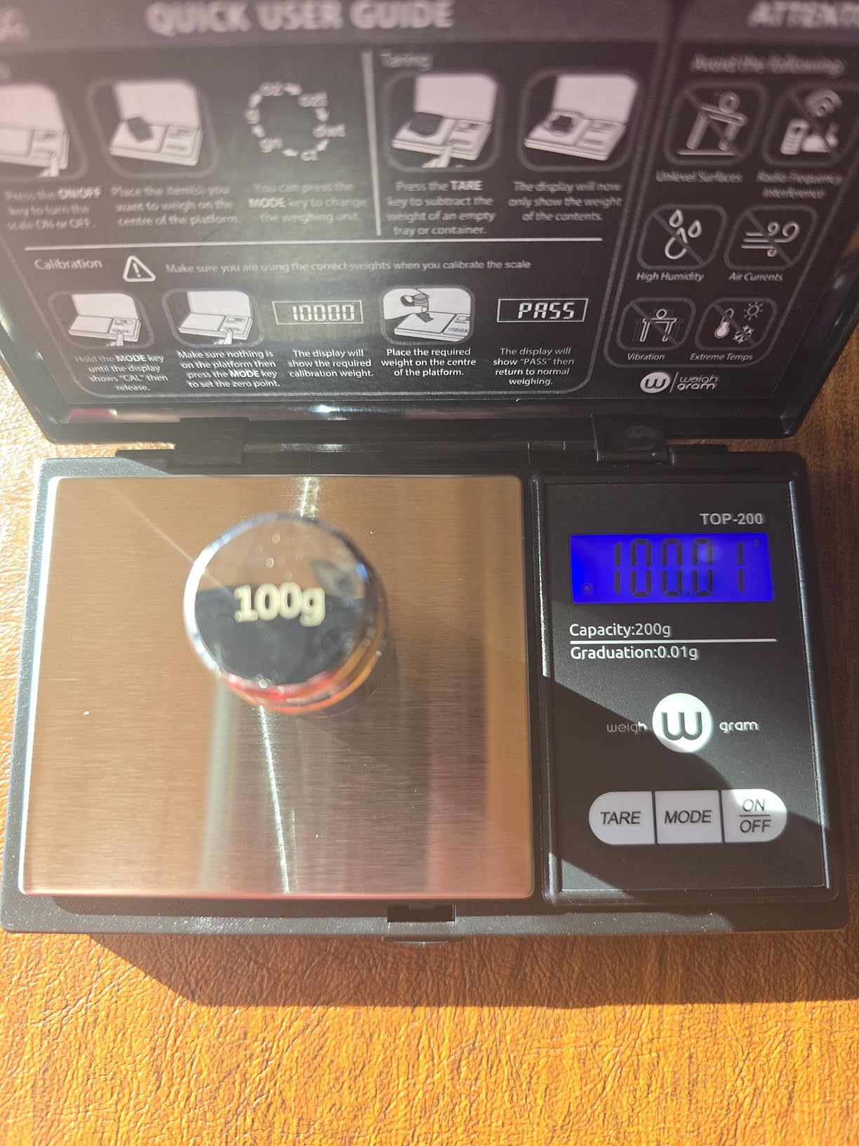
    For density testing, accuracy matters. This scale’s 0.01g precision means you can calculate density with confidence. Customer photos show it handling coins, jewelry, and small metal parts with consistent accuracy.

    Weigh Gram 200g Digital Pocket Gram Scale 0.01g Accuracy, 200g x 0.01g Mini Digital Grams Scale, Small Food Scale, Jewelry Scale, Ounces Grains Scale With100g Calibration Weight - Customer Photo 1
    Customer submitted photo

    The 200g capacity covers most small metal samples. For larger pieces, you can calculate density by weighing a section and measuring its volume. The hinged protective cover doubles as a weighing tray—perfect for odd-shaped items.

    The blue backlit display makes readings easy in any lighting. I appreciate the tare function for net weight determination—place a container on the scale, tare it, then add your metal for accurate measurement.

    Using the Scale for Density Testing

    To calculate metal density with this scale, first measure the mass of your sample. Then measure volume using the water displacement method: fill a graduated cylinder with water, record the level, submerge your metal, and record the new level.

    Weigh Gram 200g Digital Pocket Gram Scale 0.01g Accuracy, 200g x 0.01g Mini Digital Grams Scale, Small Food Scale, Jewelry Scale, Ounces Grains Scale With100g Calibration Weight - Customer Photo 4
    Customer submitted photo

    Divide mass by volume to get density. Compare your result to the reference chart. This method works for irregularly shaped pieces that can’t be easily measured.

    The multiple weight modes (g, oz, ozt, dwt, ct, gn) accommodate different applications. Ozt (troy ounce) mode is particularly useful for precious metal identification.

    Calibration for Accuracy

    This scale includes a 100g calibration weight. Calibrate before important measurements for maximum accuracy. Calibration is simple: turn on, press and hold MODE for 3 seconds until “CAL” appears, add the weight, and wait for “PASS.”

    Customer feedback confirms the scale maintains accuracy over time. One user reported consistent readings after two years of daily use. The included calibration weight ensures you can verify accuracy whenever needed.

    Weight Testing by Hand

    For quick identification without equipment, hand comparison works well. Hold a known piece in one hand and the unknown in the other. The difference becomes obvious with practice.

    I keep several reference pieces in my shop—a steel bar, aluminum bar, and copper bar of similar size. When an unknown piece comes in, I heft it against these references. The weight difference rarely lies.

    Chemical Testing: Acid Analysis for Precious Metals

    Chemical testing reveals what other methods cannot. For precious metals and jewelry, acid testing remains the most accessible definitive test. I’ve used it to verify gold purchases before reselling—saved myself from several fakes.

    How Acid Testing Works?

    Test acids are formulated to react with specific metal purities. Gold test acid reacts based on karat—10K acid affects lower purity but not 10K or higher. Silver acid turns colors indicating purity level.

    The test requires rubbing the metal on a testing stone to create a sample streak. You then apply acid and observe the reaction. No reaction means the metal meets or exceeds the acid’s rating.

    4. GTE Jewelry Testing Kit – Complete Gold Testing Solution

    COMPLETE TESTING KIT
    Product

    Jewelry Testing Kit 10K, 14K, 18K, 24K Gold, Silver, Platinum Test Solutions with Scratch Stone, 30X Loupe, Instructions, and Bamboo Storage Box

    ★★★★★★★★★★4.6 / 5

    Tests: 10K, 14K, 18K, 24K gold, silver, platinum

    Includes: Touchstone, 30X loupe, instructions

    Storage: Bamboo organizer box

    Check Price

    + Pros

    • Complete karat range covered
    • Authentic 2×2 touchstone
    • 30X loupe included
    • Organized bamboo storage
    • Fast accurate results
    • Easy-to-follow instructions

    Cons

    • Non-returnable hazardous material
    • Some bottles may leak
    • Acid bottles lack warning labels
    We earn from qualifying purchases, at no additional cost to you.

    The GTE jewelry testing kit provides everything needed for precious metal identification. Ranked #3 in Gold Testers, this kit covers the full karat range from 10K to 24K, plus silver and platinum testing solutions.

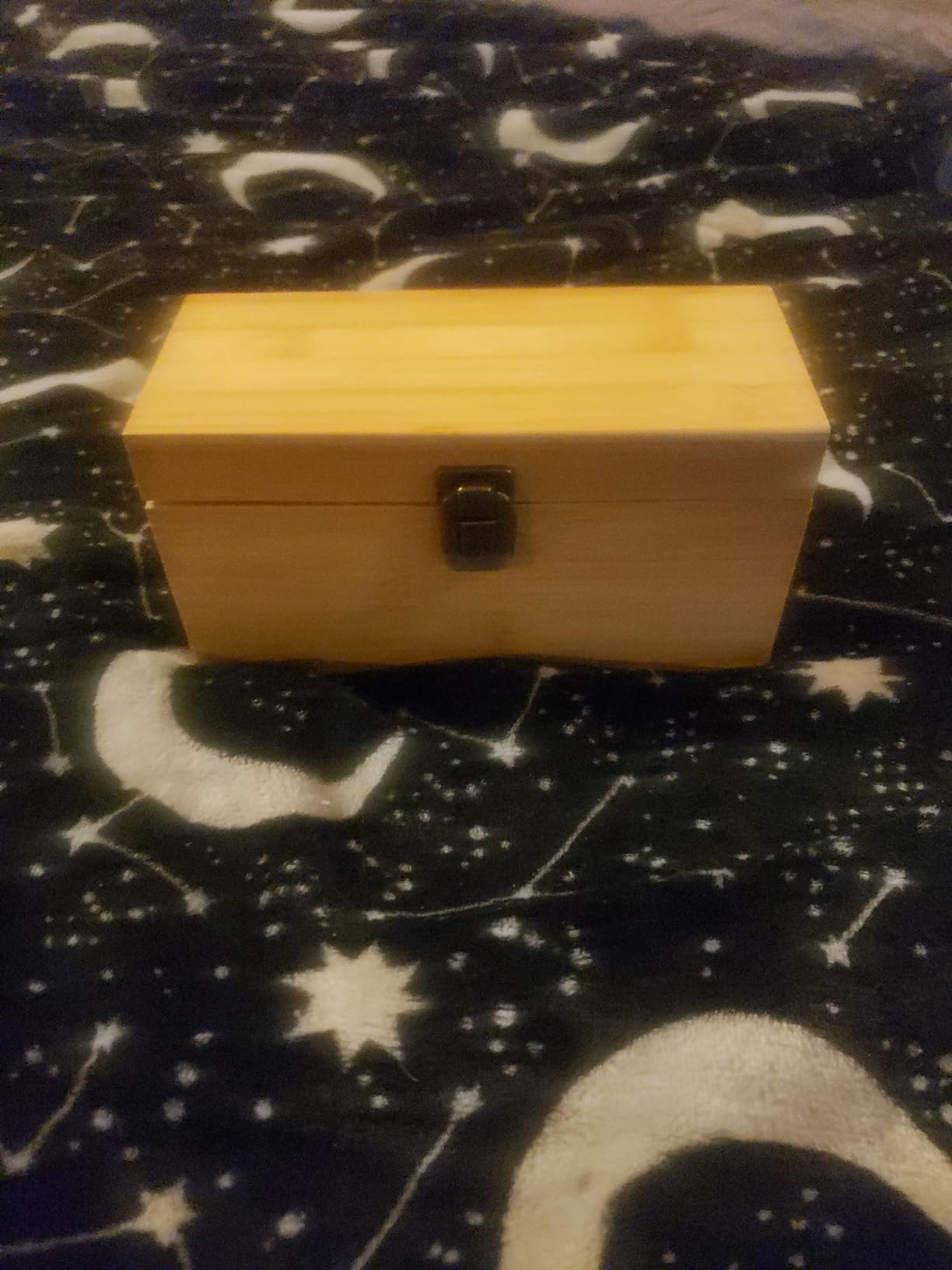
    The 2-inch touchstone creates reliable sample streaks without damaging jewelry. Customer photos show the kit’s organized layout—each acid has its designated compartment in the bamboo storage box.

    Jewelry Testing Kit 10K, 14K, 18K, 24K Gold, Silver, Platinum Test Solutions with Scratch Stone, 30X Loupe, Instructions, and Bamboo Storage Box - Customer Photo 1
    Customer submitted photo

    The included 30X jeweler’s loupe allows close inspection of hallmarks and test results. Magnification reveals details invisible to the naked eye, helping verify manufacturer stamps and test reactions.

    Testing Gold with the GTE Kit

    First, rub your gold item firmly on the touchstone to create a visible streak. Apply the lowest karat acid first (usually 10K). If the streak remains unchanged, the gold is at least 10K.

    Progress to higher acid concentrations. 14K acid on 10K gold will dissolve the streak. 18K acid on 14K gold reacts similarly. The highest acid that doesn’t affect the streak indicates the gold’s purity.

    Jewelry Testing Kit 10K, 14K, 18K, 24K Gold, Silver, Platinum Test Solutions with Scratch Stone, 30X Loupe, Instructions, and Bamboo Storage Box - Customer Photo 3
    Customer submitted photo

    Customer reviews confirm this method works consistently. Metal detector enthusiasts use it to identify found jewelry, often discovering pieces are higher purity than expected.

    Silver and Platinum Testing

    The kit includes solutions for silver and platinum identification. Silver test acid turns red on low-grade silver and dark brown on sterling (.925). Platinum has its own specific test solution.

    These secondary tests make the kit versatile. I’ve identified everything from costume jewelry to antique silver using this single kit. The solutions last about a year once opened when stored properly.

    Safety Considerations

    Chemical testing requires precautions. Work in a well-ventilated area, wear gloves and eye protection, and keep baking soda nearby to neutralize spills. The acids are corrosive and can damage surfaces.

    Jewelry Testing Kit 10K, 14K, 18K, 24K Gold, Silver, Platinum Test Solutions with Scratch Stone, 30X Loupe, Instructions, and Bamboo Storage Box - Customer Photo 5
    Customer submitted photo

    The bamboo storage box helps organize the acids but lacks clear warning labels. I recommend labeling the box clearly and keeping it away from children and pets.

    Chemical Testing Limitations

    Acid testing is destructive—it removes a tiny amount of metal. For valuable antiques, consider XRF testing instead. Plated items also test differently; you must reach through the plating to test the base metal.

    Modern Methods: XRF and Spectroscopy

    Professional metal identification has moved beyond visual and destructive tests. XRF analyzers and optical emission spectrometers provide instant, accurate elemental analysis. These tools represent the gold standard for metal identification.

    XRF Analysis Explained

    XRF works by bombarding the sample with X-rays. The atoms in the metal become excited and release fluorescent X-rays at specific energy levels characteristic of each element. The detector measures these emissions and calculates the complete composition.

    The entire process takes seconds. Point the device at the metal, pull the trigger, and read the results. No sample preparation, no damage, no waiting.

    When XRF Makes Sense

    For hobbyists and small shops, XRF is overkill. The high cost is difficult to justify unless you’re testing valuable metals frequently. Scrap yards with high volume, manufacturing facilities with strict quality requirements, and jewelry businesses benefit most.

    I’ve used rental XRF units for specific projects—verifying alloy composition for critical aerospace parts, for example. The peace of mind from definitive analysis was worth the rental cost.

    Common Metal Comparisons: Look-Alikes Explained

    Some metals frustrate beginners because they look nearly identical. I’ve seen experienced metalworkers confused by certain look-alikes. Here’s how to tell the common tricky pairs apart.

    Steel vs Aluminum

    Weight Difference: Aluminum weighs approximately one-third as much as steel for the same size piece. This dramatic weight difference makes hand comparison the easiest identification method.

    Steel and aluminum appear similar at first glance—both grayish metals. But the weight difference is dramatic. Pick up a steel rod, then an aluminum one of the same size. The aluminum feels noticeably lighter.

    The magnet test provides instant confirmation. Steel attracts strongly; aluminum has no magnetic response. Spark testing also works—steel produces sparks, aluminum doesn’t.

    Stainless Steel vs Regular Steel

    Stainless steel looks brighter and more reflective than carbon steel. The surface often has a smoother, almost chrome-like appearance. Carbon steel appears darker gray and may show surface rust.

    The magnet test helps here, but with nuance. 304 and 316 stainless (the most common grades) won’t attract magnets. But 400 series stainless will attract, similar to carbon steel.

    Spark testing provides clearer distinction. Stainless produces short, orange-red sparks. Carbon steel creates longer, yellow-white sparks with more branching.

    Brass vs Bronze

    Brass and bronze confuse many people—both are copper alloys with similar golden appearance. But the color difference becomes obvious once you know what to look for.

    Brass appears brighter yellow, almost like dull gold. Bronze looks more muted, with a brownish-gold tone. Think of brass as “yellow” and bronze as “brown.”

    Weight also differs slightly. Bronze is denser (8.7 g/cm3) than brass (8.4 g/cm3). In hand, bronze feels marginally heavier for the same size piece.

    Sound provides another clue. Tap each metal—brass produces a brighter ring, bronze a duller tone. This auditory test works best with thin pieces like pipes or sheets.

    Identification Cheat Sheet

    ComparisonBest TestKey Difference
    Steel vs AluminumWeight comparisonAluminum 1/3 the weight
    Stainless vs Carbon SteelSpark testSpark length and color
    Brass vs BronzeColor examinationBrass yellow, bronze brown
    Copper vs Rose GoldAcid testCopper reacts, gold doesn’t
    Titanium vs SteelWeight + sparkTitanium lighter, no sparks

    Safety Considerations for Metal Testing

    Metal identification isn’t inherently dangerous, but some testing methods carry risks. I’ve seen minor injuries that could have been prevented with proper precautions. Safety deserves as much attention as technique.

    Spark Testing Safety

    Spark testing creates hot, flying metal particles. Eye protection is non-negotiable. I use a full face shield when spark testing—regular safety glasses don’t protect against sparks that might deflect upward.

    Flammable materials must be removed from the spark zone. Sparks travel 10 feet or more and can ignite sawdust, paper, or solvent fumes. Clear your work area before starting.

    The grinding wheel itself poses risks. Never start the wheel with the workpiece touching the surface. Let the wheel reach full speed before making contact. And never stand directly in front of a grinder when starting it.

    Chemical Testing Safety

    Test acids are corrosive substances that can cause severe burns. I always wear nitrile gloves and eye protection when acid testing. Work in a well-ventilated area—some acids release fumes.

    Keep baking soda or another neutralizing agent nearby. If acid spills on skin, rinse immediately with water for at least 15 minutes. If acid gets in eyes, flush with water and seek medical attention.

    Store acids properly. The GTE kit’s bamboo box helps, but I keep mine in a secondary container labeled clearly. Keep acids away from children and pets. The non-returnable nature of these kits exists for good reason—shipping hazardous materials carries risk.

    General Metal Handling Safety

    Scrap metal often has sharp edges. I wear cut-resistant gloves when handling unknown pieces. Sheet metal edges are notorious for causing cuts—even pieces that appear smooth can have razor-sharp burrs.

    Heavy pieces require proper lifting technique. Bend at the knees, not the back. Metal pieces are denser than they appear and can cause back injuries if lifted improperly.

    Some metals produce toxic fumes when heated or ground. Galvanized steel releases zinc oxide when heated—this causes metal fume fever. Cadmium-plated metals pose similar risks. Know what you’re working with before applying heat.

    Step-by-Step Metal Identification Workflow

    After years of practice, I’ve developed a systematic approach to metal identification. Following a consistent workflow produces more accurate results than randomly trying methods.

    Beginner Workflow

    1. Visual Inspection: Check color, surface, and markings first
    2. Magnet Test: Separate ferrous from non-ferrous
    3. Weight Comparison: Compare to known samples
    4. Confirm with Second Method: Verify initial identification
    5. Document Results: Label or mark identified pieces

    Advanced Workflow

    1. Check Markings: Look for stamps, grade markings, or part numbers
    2. Visual + Magnet: Initial categorization
    3. Density Calculation: Precise weight and volume measurement
    4. Spark Test (if ferrous): Determine carbon content
    5. Chemical Test (if precious): Verify karat or purity
    6. Professional Verification: XRF or lab test for critical applications

    Pro Tip: Build a reference collection of known metals. Label each piece clearly and keep them together. When you encounter an unknown piece, compare it directly to your references. This practice dramatically improves identification accuracy over time.

    DIY Projects
    Scrap Sorting
    Welding Prep
    Jewelry Verification

    Frequently Asked Questions

    How can you tell what metal something is?

    Start with a magnet test to separate ferrous from non-ferrous metals. Then examine the color and weight. Steel is magnetic and heavy, aluminum is non-magnetic and light, copper is reddish and very heavy, and brass is yellowish-gold and moderately heavy. For definitive identification, combine multiple methods rather than relying on a single test.

    What is the easiest way to identify metal?

    The magnet test combined with visual inspection is the easiest method for beginners. A strong magnet will immediately identify ferrous metals like steel and iron, while non-magnetic response narrows it down to aluminum, copper, brass, bronze, or most stainless steels. Then examine the color—copper is reddish, brass is yellow-gold, aluminum is light gray, and stainless is bright silver-gray.

    What are the methods of metal identification?

    The seven main metal identification methods are: visual inspection (color and markings), magnetic testing (ferrous detection), density testing (weight measurement), spark testing (carbon analysis), hardness testing (scratch resistance), chemical testing (acid reaction), and spectroscopic analysis (XRF). Most people start with visual and magnetic tests, then progress to density or spark testing as needed.

    How do you identify ferrous and non-ferrous metals?

    The magnet test is the definitive method for distinguishing ferrous from non-ferrous metals. Ferrous metals containing iron (steel, cast iron, some stainless grades) will attract to a magnet. Non-ferrous metals (aluminum, copper, brass, bronze, most stainless) will not attract. However, note that some stainless steels in the 400 series are magnetic, while 300 series stainless is non-magnetic.

    What is spark testing in metallurgy?

    Spark testing is a metal identification method where metal is ground against a high-speed abrasive wheel. The resulting spark stream reveals the metal’s carbon content and alloy composition. High-carbon steel produces long, bright sparks with many branches. Low-carbon steel creates shorter, straighter sparks. Stainless steel generates short orange-red sparks, while cast iron produces numerous small sparks in a bushy pattern.

    How accurate is XRF metal analysis?

    XRF metal analysis provides 99.9% accuracy for most elements in the periodic table. The technology measures elemental composition without damaging the sample, delivering results in seconds. However, XRF has limitations with light elements like lithium, beryllium, and sodium. Surface coatings can also affect readings, so testing may require light grinding to reach the base metal.

    How do you tell stainless steel from aluminum?

    Stainless steel and aluminum can be distinguished by three main tests. First, weight: aluminum weighs approximately one-third as much as stainless steel for the same size. Second, magnetism: some stainless grades attract magnets while aluminum never does. Third, spark test: stainless produces short orange-red sparks, while aluminum creates no spark stream, only small glowing particles.

    What is the difference between brass and bronze?

    Brass and bronze are both copper alloys but with distinct differences. Brass is copper plus zinc, appearing bright yellow-gold. Bronze is copper plus tin, appearing more muted with brownish-gold tones. Brass is slightly less dense than bronze (8.4 vs 8.7 g/cm3), making bronze feel marginally heavier for the same size piece. Bronze also produces a duller sound when tapped compared to brass’s brighter ring.

    Getting Started with Metal Identification

    Metal identification starts with the basics and builds from there. Begin with visual inspection and a magnet test—these two methods alone identify most common metals. As you gain experience, add density testing and spark testing to your repertoire.

    The equipment investments that provide the most value are a strong neodymium magnet, a digital scale, and a basic grinding wheel for spark testing. These three tools, combined with practice, will identify 95% of metals you’ll encounter.

    Remember that no single method is perfect. The most accurate identification comes from combining multiple tests and cross-referencing results. When accuracy matters for critical applications, professional testing provides definitive answers worth the investment.

  • Carbon Arc Cutting Explained: Equipment, Benefits August 2026

    Carbon Arc Cutting Explained: Equipment, Benefits August 2026

    Carbon arc cutting is one of the most powerful metal removal processes in industrial fabrication. When I first encountered it in a shipyard, I watched a welder slice through inch-thick steel plate like butter, leaving a clean groove in seconds. The speed and raw power of CAC carbon arc cutting make it indispensable for heavy industry.

    Air carbon arc cutting (CAC-A) is a thermal cutting process that uses a carbon or graphite electrode to create an electric arc that melts metal. A high-velocity jet of compressed air then blows away the molten metal, allowing for cutting or gouging operations. CAC can cut all metal types including stainless steel and cast iron that oxy-fuel cannot process.

    After working with fabrication shops across the country, I have seen CAC carbon arc cutting become the go-to method for weld removal, back gouging, and preparing joints. The process handles everything from maintenance welding repairs to full-scale structural steel fabrication. It works in any position, cutting through materials that would stop other thermal cutting methods cold.

    How Carbon Arc Cutting Works?

    Quick Summary: Carbon arc cutting uses an electric arc between a carbon electrode and the workpiece to melt metal (up to 6,000F). Compressed air flowing through the electrode holder blows the molten metal away, creating a cut or groove. The process requires a constant current power source, compressed air at 80-100 PSI, and proper polarity settings.

    The physics behind CAC carbon arc cutting rely on two simultaneous actions. First, an electric arc forms between the carbon electrode and the metal workpiece. This arc generates intense heat, reaching temperatures up to 6,000 degrees Fahrenheit. At these temperatures, virtually any metal melts within seconds.

    As the metal liquefies, the second critical action takes place. Compressed air flows through the electrode holder and exits at high velocity directly behind the arc. This air jet, typically at 80-100 PSI, blasts the molten metal away from the workpiece. The result is a clean cut or groove without the oxidation that occurs with oxy-fuel cutting.

    The carbon electrode itself plays a vital role. Unlike coated welding electrodes, carbon electrodes conduct current while withstanding extreme arc temperatures. They gradually wear down during use, consuming at rates between 6-12 inches per hour depending on amperage and application.

    Cutting vs. Gouging: What’s the Difference?

    Cutting: Severing metal completely by penetrating through the entire thickness. The electrode moves continuously along the cut line.

    Gouging: Removing a portion of metal without cutting through completely. Creates a groove or cavity for weld preparation or defect removal.

    In my experience, gouging accounts for about 70% of CAC applications. Back gouging for full penetration welds, removing defective welds, and preparing joints are far more common than cutting through plate. The control you have with gouging lets you create precise grooves for later welding.

    Cutting through material requires higher amperage and larger electrodes. The goal is complete penetration, so you need enough heat to melt through the entire thickness. Gouging uses lower amperage and smaller electrodes for better control of groove depth and width.

    Essential Equipment for Carbon Arc Cutting

    Setting up for CAC carbon arc cutting requires specific equipment. I have seen shops try to cut corners and pay the price in poor results or equipment damage. Each component plays a critical role in the process.

    EquipmentSpecificationPurpose
    Power SourceConstant Current (CC), 200-600AProvides stable arc current
    Air Compressor5-50 CFM, 80-100 PSIDelivers high-velocity air jet
    Electrode HolderRated for electrode size and amperageHolds electrode, conducts current and air
    Carbon Electrodes1/8″ to 5/8″ diameter, DC or ACCreates arc, withstands heat
    Air Hose3/8″ to 1/2″ ID, minimum 25 ftDelivers compressed air to holder
    Ground Clamp300-600A rated, clean connectionCompletes electrical circuit

    Power Source Requirements

    The welding machine for CAC carbon arc cutting must be a constant current (CC) power source. Unlike constant voltage (CV) machines used for MIG welding, CC maintains stable amperage as the arc length varies. This stability is crucial for consistent cutting and gouging results.

    Most shops use existing DC welding machines. A 300-amp CC welder handles most applications up to 1/2 inch material. Heavy-duty work on thicker materials requires 400-600 amps. I have worked with maintenance crews who successfully used 200-amp machines for light gouging, but you are limited on electrode size and cutting capacity.

    For standard CAC-A operations, connect the electrode to the negative terminal (DCEN or DC electrode negative). This reverse polarity setup produces the most stable arc and fastest electrode consumption. AC-only machines require special AC carbon electrodes, but DC provides better results in most applications.

    Air Requirements

    Nothing stops a CAC operation faster than inadequate air supply. The compressed air does the actual work of removing molten metal. Without sufficient volume and pressure, the process fails regardless of how much amperage you have.

    Electrode SizeAmperage RangeCFM RequiredMin. Compressor HP
    1/8″ (3.2mm)60-150A5-8 CFM1.5-2 HP
    3/16″ (4.8mm)150-250A8-15 CFM3-5 HP
    1/4″ (6.4mm)250-400A15-25 CFM5-7.5 HP
    3/8″ (9.5mm)350-550A25-35 CFM7.5-10 HP
    1/2″ (12.7mm)500-700A35-50 CFM10-15 HP

    Air pressure should be set between 80-100 PSI at the torch. Higher pressure improves metal removal but increases electrode consumption and spark throw. I typically start at 90 PSI and adjust based on the application.

    Carbon Electrodes

    Carbon electrodes come in various sizes and compositions. Standard electrodes are a mixture of carbon and graphite. Pure graphite electrodes offer cleaner cutting with less carbon pickup but cost significantly more.

    Electrode diameter directly affects cutting capacity and amperage requirements. Small electrodes (1/8″) work well for light gouging and precision work. Large electrodes (3/8″ to 1/2″) handle heavy-duty cutting and deep gouging in thick materials.

    In my work with railroad maintenance teams, we primarily use 1/4″ electrodes as a versatile all-around size. They handle most gouging tasks while still providing enough capacity for cutting through rail sections when needed.

    Applications and Uses of Carbon Arc Cutting

    CAC carbon arc cutting serves numerous applications across heavy industry. The ability to remove metal quickly while working in any position makes it invaluable for maintenance and fabrication work.

    Weld Removal
    Back Gouging
    Cast Iron Repair
    Joint Preparation
    Defect Removal

    Weld Removal and Repair

    The most common application I encounter is removing defective or unwanted welds. When a weld fails inspection, carbon arc gouging removes it faster than any other method. The process cleanly extracts weld metal without damaging the base material, allowing for proper repair.

    I have worked with pressure vessel manufacturers who rely on CAC for removing root passes during rework. The precision of gouging lets them remove just the weld metal, leaving the base material intact for proper repair welding.

    Back Gouging

    Full penetration welds require back gouging from the reverse side. CAC carbon arc cutting excels at this application. After completing the root pass from one side, you gouge out the root from the opposite side before welding it out.

    This creates a clean, contoured groove that ensures complete fusion through the entire joint thickness. Shipyards use this technique extensively on hull plates and structural members. The ability to gouge overhead makes CAC ideal for shipbuilding where position welding is common.

    Cast Iron Repair

    Cast iron presents unique challenges for welding and cutting. Oxy-fuel cutting does not work on cast iron due to its lack of iron oxide. CAC cuts through cast iron cleanly, making it the preferred method for repairing castings.

    Engine blocks, machine bases, and agricultural equipment often require cast iron repair. I have helped machine shops salvage expensive castings by gouging out cracks and defects before welding repairs.

    Industrial Applications by Sector

    IndustryPrimary CAC UsesTypical Materials
    ShipbuildingBack gouging, weld removal, prep workMild steel, stainless steel
    Heavy EquipmentCrack repair, component rebuildSteel, cast iron, wear plate
    Structural SteelJoint prep, modification, demolitionA36 steel, alloy steels
    RailroadRail repair, frog replacementHigh carbon steel, manganese steel
    MiningEquipment repair, bucket rebuildWear resistant steels, AR plate

    Advantages and Disadvantages of Carbon Arc Cutting

    Like any industrial process, CAC carbon arc cutting has distinct strengths and limitations. Understanding these helps determine when CAC is the right choice for your application.

    Key Advantages

    1. Cuts All Metal Types: Unlike oxy-fuel cutting, CAC works on any conductive metal. Stainless steel, cast iron, aluminum, copper alloys—nothing is off-limits. This versatility makes CAC invaluable in mixed-material fabrication shops.
    2. Fast Metal Removal: No other manual method removes metal as quickly. I have watched skilled operators remove weld metal at rates exceeding 50 pounds per hour. For production gouging operations, this speed translates directly into cost savings.
    3. All-Position Capability: Work overhead? Underneath? In confined spaces? CAC handles all positions equally well. The gravity-independent air jet removes molten metal regardless of torch orientation. This flexibility makes CAC essential for field repair work.
    4. Cost-Effective Equipment: Most shops already have compatible welding machines. Adding CAC capability requires only the torch, air supply, and electrodes. Compared to plasma cutting systems with similar capacity, CAC equipment costs significantly less.
    5. Portable Operation: A CAC setup fits in a pickup truck. Field repairs on construction sites, farm equipment, or mining machinery become feasible with portable air supply. I have used CAC for on-site repairs in locations where bringing material to a shop was impossible.
    6. No Oxidation Required: Oxy-fuel cutting depends on rapid oxidation of iron. CAC works purely through melting and air blasting. This means cleaner cuts on materials susceptible to oxidation problems.

    Key Disadvantages

    1. Extreme Noise Levels: CAC generates noise up to 118 dB—comparable to a jet engine at close range. This necessitates dual hearing protection (ear plugs plus muffs) and creates workplace noise challenges. After a day of carbon arc work, your ears will ring without proper protection.
    2. Spark Throw: Molten metal sparks travel 20-30 feet from the work area. This creates significant fire hazards and requires clearing the work zone of flammable materials. I have seen sparks ignite debris 25 feet away during heavy gouging operations.
    3. Smoke and Fumes: The process generates substantial smoke, especially when cutting through coated or contaminated materials. Proper ventilation is non-negotiable. In confined spaces, respiratory protection becomes mandatory.
    4. Air Compressor Required: The compressed air requirement adds complexity and cost. High CFM needs mean large compressors or limited duty cycles. Portable operations become challenging when air supply is limited.
    5. Not for Precision Cutting: CAC is a rough cutting process. Tolerances are measured in fractions of an inch, not thousandths. For precision work, other methods like plasma or laser cutting produce superior results.
    6. Carbon Pickup: The carbon electrode can deposit carbon into the workpiece, particularly on stainless steels. This carbon pickup can affect corrosion resistance and requires additional cleaning before welding. Post-gouging grinding becomes necessary for critical applications.

    Preventing Carbon Pickup

    Carbon pickup remains a concern for stainless steel applications. The carbon electrode can transfer small amounts of carbon into the workpiece during gouging, potentially compromising corrosion resistance.

    To minimize carbon pickup on stainless steel:

    • Use copper-coated electrodes designed for stainless work
    • Keep the torch angle closer to perpendicular (less than 30 degrees from surface)
    • Grind at least 1/16″ of material from the gouged surface before welding
    • Consider mechanical gouging methods for critical stainless applications

    After consulting with food processing plant maintenance teams, I learned they avoid CAC on stainless steel surfaces that contact food products. For less critical stainless applications, proper post-gouging cleaning typically resolves any carbon pickup concerns.

    Safety Precautions for Carbon Arc Cutting

    Safety must be the top priority when working with CAC carbon arc cutting. The process combines electrical hazards, extreme heat, high-pressure air, and intense noise into one potentially dangerous operation.

    Hearing Protection

    The noise from CAC operations can cause permanent hearing damage in minutes. At 118 dB, exposure time before damage occurs is measured in seconds, not hours. This is not something to take lightly.

    HEARING PROTECTION IS MANDATORY:

    • Use dual protection: ear plugs PLUS ear muffs
    • Ensure proper fit for both devices
    • Replace ear plugs daily (or use reusable plugs cleaned regularly)
    • Take breaks in quiet areas to reduce cumulative exposure
    • Consider audiometric testing for regular CAC operators

    I have worked with welders who have permanent hearing loss from years of carbon arc work without proper protection. The damage is cumulative and irreversible. Hearing protection is not optional—it is essential.

    Eye and Face Protection

    The intense arc from CAC produces dangerous UV radiation, similar to welding. Without proper eye protection, arc flash (welder’s flash) can occur. This painful condition feels like sand in your eyes and can cause temporary blindness.

    A welding helmet with shade 10-14 provides adequate protection. For gouging operations, I recommend a shade 12 lens. Face shields add an extra layer of protection against flying sparks and debris, especially during overhead work.

    Safety glasses under the helmet protect against sparks that might find their way around the helmet seal. Polycarbonate lenses with side shields offer the best protection.

    Respiratory Protection and Ventilation

    CAC operations generate significant smoke and fumes. The composition varies depending on the base metal and any coatings present. Common contaminants include metal oxides, flux residues, and thermal decomposition products from paints or coatings.

    General ventilation guidelines:

    • Minimum 100 CFM airflow in the work area
    • Local exhaust ventilation recommended for any enclosed work
    • Position portable exhaust units to capture smoke at the source
    • Avoid standing directly in the smoke plume

    For confined space operations, respiratory protection becomes mandatory. An N95 respirator provides minimum protection for light work. For heavy gouging or work on coated materials, a powered air-purifying respirator (PAPR) offers superior protection.

    Fire Safety

    The spark throw from CAC creates significant fire hazards. Sparks can travel 20-30 feet and remain hot enough to ignite combustible materials. I personally witnessed a CAC operation ignite sawdust in a woodworking shop three bays away.

    Fire safety protocols:

    • Clear 30-foot radius of all combustible materials
    • Keep a fire extinguisher rated for Class ABC fires within reach
    • Assign a fire watch when working near combustible materials
    • Check behind walls and partitions for hidden combustibles
    • Welding blankets protect adjacent surfaces from spark damage
    • Monitor the work area for at least 30 minutes after completing work

    Electrical Safety

    CAC equipment operates at high amperage and voltages up to 80 volts open circuit. While less dangerous than high-voltage systems, the electrical hazards still demand respect.

    Electrical safety practices:

    • Inspect cables and connections before each use
    • Ensure proper grounding of the workpiece
    • Never touch the electrode holder with bare hands while powered
    • Use dry gloves and boots for insulation
    • Keep cables away from walking areas to prevent damage
    • Disconnect power before changing electrodes

    Step-by-Step Carbon Arc Cutting Guide

    Equipment Setup

    1. Connect the Power: Attach the work cable to the positive terminal and the electrode cable to the negative terminal (DCEN polarity). Ensure connections are tight and clean.
    2. Connect the Air: Attach the air hose to the electrode holder. Check all connections for leaks. A soap solution sprayed on fittings reveals air leaks quickly.
    3. Set the Pressure: Adjust the air compressor regulator to 90 PSI at the torch. Verify pressure with a gauge at the holder, not just at the compressor.
    4. Select Electrode Size: Choose the appropriate diameter for your application and material thickness. Larger electrodes remove more metal but require higher amperage.
    5. Set Amperage: Adjust the welder to the recommended amperage for your electrode size. A 1/4″ electrode typically runs at 300-400 amps for gouging.

    Preparing the Workpiece

    Clean the work area of any flammable materials within a 30-foot radius. Attach the ground clamp to clean bare metal, as close to the work area as possible. A poor ground connection causes erratic arc performance and can damage equipment.

    Mark your cut or gouge line clearly. For gouging operations, outline the groove width and depth with chalk or soapstone. Having a clear guide helps maintain consistent results.

    Striking the Arc

    Position the electrode at a 30-45 degree angle to the work surface. The air jet should point in the direction of travel. Hold the torch with both hands for stability.

    Tap the electrode against the workpiece like striking a match, then lift slightly to establish the arc. Once the arc forms, the air will begin flowing and metal removal starts immediately.

    A common mistake I see beginners make is holding the electrode too far from the work. Maintain a short arc length—about 1/8 to 1/4 inch. Longer arcs cause spatter and reduce cutting efficiency.

    Gouging Technique

    For gouging operations, move the torch smoothly along your marked line. The travel speed affects groove depth—slower creates deeper grooves, faster creates shallower ones. Maintain consistent torch angle and travel speed for uniform results.

    Weave the torch slightly side-to-side to widen the groove. The air jet naturally creates a U-shaped groove profile. Adjust torch angle to control the groove shape.

    For deep gouging, make multiple passes rather than trying to remove all material at once. Two or three lighter passes produce better control and cleaner results than one aggressive pass.

    Cutting Through Material

    When cutting completely through material, start at the edge if possible. Establish the arc and let it penetrate through the full thickness before beginning to travel. Move at a steady pace that allows complete penetration.

    For starting cuts in the middle of a plate, create a starter hole by holding the torch stationary until penetration occurs. Then begin your cut line from this point.

    Finishing Up

    After completing your cut or gouge, release the trigger and break the arc. The air continues flowing briefly to cool the electrode and clear remaining molten metal.

    Allow the workpiece to cool before handling. The freshly cut edges remain extremely hot immediately after cutting. Use pliers or tongs if you must move hot material.

    Clean the gouged surface with a wire brush to remove slag and carbon deposits. For welding applications, grind the surface to remove any carbon-affected layer before welding.

    Carbon Arc Cutting vs Other Cutting Methods

    Choosing the right cutting method depends on your specific application, material type, and available equipment. CAC excels in certain areas while other methods may be more appropriate for different tasks.

    FactorCarbon Arc (CAC)Plasma CuttingOxy-Fuel Cutting
    Metals That Can Be CutAll conductive metalsAll conductive metalsFerrous metals only
    Cut QualityRough, requires cleanupClean, preciseRough, slag buildup
    SpeedVery fast gougingFast cuttingMedium speed
    Equipment CostLow (uses welder + air)Medium to highLow to medium
    Operating CostElectrodes + electricity + airElectricity + consumablesOxygen + fuel gas
    PrecisionLow (+/- 1/8″)High (+/- 1/32″)Medium (+/- 1/16″)
    Noise LevelVery high (110-118 dB)Medium (80-100 dB)Medium (90-105 dB)

    When to Choose Carbon Arc Cutting?

    Select CAC when you need to remove metal quickly from any material type, particularly for gouging applications. The process dominates in weld removal, back gouging, and joint preparation. If you already own a CC welding machine and air compressor, CAC becomes the most economical choice for heavy metal removal.

    For cast iron work, CAC has no equal among manual processes. The ability to gouge and cut cast iron without preheating makes it indispensable for engine and equipment repair.

    When to Choose Plasma Cutting?

    Plasma cutting provides superior cut quality and precision. For fabrication work requiring clean edges or tight tolerances, plasma outperforms CAC. Plasma also produces less noise and fewer sparks, making it more suitable for shop environments.

    The higher equipment cost of plasma systems becomes justified when precision and cut quality matter. Production cutting operations typically choose plasma for cleaner results and faster cutting speeds on thinner materials.

    When to Choose Oxy-Fuel Cutting?

    Oxy-fuel excels at cutting thick ferrous materials (over 2 inches). For severing heavy steel plate, oxy-fuel often proves faster and more economical than CAC. The equipment is portable and requires no electricity, making it ideal for field work.

    However, oxy-fuel cannot cut non-ferrous metals like stainless steel, aluminum, or copper. For these materials, you must choose CAC or plasma.

    Frequently Asked Questions

    How many CFM do I need for carbon arc gouging?

    Air requirements vary by electrode size. Small electrodes (1/8 inch) need 5-8 CFM. Medium electrodes (1/4 inch) require 15-25 CFM. Large electrodes (3/8 to 1/2 inch) demand 25-50 CFM. Always size your compressor for the largest electrode you plan to use, plus a 20% safety margin for consistent air supply during extended gouging operations.

    What is the CAC-A cutting process?

    Air carbon arc cutting (CAC-A) is a thermal cutting process that uses a carbon or graphite electrode to create an electric arc melting the base metal. A high-velocity jet of compressed air then blows away the molten metal, allowing for cutting or gouging operations. The process works on all conductive metals including stainless steel and cast iron.

    Is carbon arc gouging CC or CV?

    Carbon arc gouging requires a Constant Current (CC) power source, not Constant Voltage (CV). CC welding machines maintain stable amperage as arc length varies, which is essential for consistent gouging results. Standard DC welding machines with CC output work well for CAC when set to DC electrode negative (DCEN) polarity.

    What are the disadvantages of carbon arc cutting?

    Key disadvantages include extreme noise levels up to 118 dB requiring dual hearing protection, sparks that travel 20-30 feet creating fire hazards, significant smoke and fumes requiring ventilation, high air compressor requirements (up to 50 CFM), lack of precision for fine work, and potential carbon pickup on stainless steels requiring post-gouging cleaning.

    What materials can you cut with carbon arc cutting?

    CAC works on all electrically conductive metals. This includes ferrous metals like carbon steel and alloy steels, non-ferrous metals like stainless steel, aluminum, copper, and brass, plus cast iron which oxy-fuel cannot cut. It is not recommended for reactive metals like titanium or zirconium without thorough post-cutting cleaning due to carbon pickup concerns.

    What are the main advantages of carbon arc cutting?

    Main advantages include the ability to cut all metal types (unlike oxy-fuel), very fast metal removal rates up to 50 pounds per hour, works in all positions including overhead, cost-effective using existing welding equipment, portable for field repairs, and does not require oxidation like oxy-fuel cutting. The process excels at gouging applications like weld removal and joint preparation.

    How loud is carbon arc gouging?

    Carbon arc gouging generates noise levels up to 118 dB, which is comparable to a jet engine at close range. This level causes permanent hearing damage in minutes without protection. Dual hearing protection (ear plugs plus ear muffs) is mandatory. The noise comes from the high-velocity air jet combined with the violent removal of molten metal.

    What PSI is needed for arc gouging?

    Air pressure of 80-100 PSI at the torch is recommended for carbon arc gouging. Higher pressure improves metal removal rate but increases electrode consumption and spark throw. Start at 90 PSI and adjust based on your specific application. Ensure your air compressor can maintain this pressure while delivering the required CFM for your electrode size.

    Conclusion

    CAC carbon arc cutting remains one of the most versatile and powerful metal removal processes available to industry. From shipyards to fabrication shops, the ability to quickly remove metal from any conductive material makes CAC indispensable for maintenance and fabrication work.

    The process demands respect for its hazards—especially the extreme noise levels and fire risks from spark throw. Proper safety equipment and procedures are non-negotiable. But with appropriate precautions, CAC delivers unmatched performance for gouging, weld removal, and metal cutting applications.

    Whether you are preparing joints for welding, removing defective welds, or repairing cast iron equipment, carbon arc cutting provides a solution that works on any metal, in any position, with equipment you may already own. Mastering CAC adds a powerful tool to your metalworking capabilities.

  • Flux Core Welding: Complete Guide to FCAW Process

    Flux Core Welding: Complete Guide to FCAW Process

    After spending 15 years in metal fabrication and testing every welding process under the sun, I’ve learned that flux core welding gets a bad reputation it doesn’t deserve.

    When I first started welding, I struggled with MIG welding outdoors. The slightest breeze would blow away my shielding gas and create porosity in my welds. A mentor handed me a spool of flux core wire and told me to try it. Within an hour, I was making solid welds in windy conditions that would have been impossible with solid MIG wire.

    What is Flux Core Welding?

    The flux inside the hollow wire does the work that shielding gas does in MIG welding. When the arc melts the wire, the flux vaporizes to create shielding gas and forms a layer of slag over the cooling weld.

    FCAW: Flux-Cored Arc Welding – the technical industry term for what most welders call flux core welding.

    This self-contained protection system makes flux core uniquely capable of welding in conditions that would ruin other processes. I’ve welded in 20 mph winds, on rusty farm equipment, and even in light rain using self-shielded flux core.

    Types of Flux Core Welding

    Quick Summary: There are two main types of flux core welding – self-shielded (FCAW-S) needs no gas and is perfect for outdoor work, while gas-shielded (FCAW-G) produces cleaner welds but requires external shielding.

    Understanding the difference between these two types is crucial because they serve completely different purposes. Choosing the wrong one for your application can lead to frustrating results.

    Self-Shielded Flux Core (FCAW-S)

    FCAW-S: Self-Shielded Flux-Cored Arc Welding – the flux core provides complete shielding without any external gas. This is what most people mean when they say “gasless” welding.

    Self-shielded flux core is the go-to choice for outdoor welding and field work. I’ve used it extensively for farm repairs, fence welding, and construction projects where dragging a gas cylinder isn’t practical.

    The wire contains flux compounds that vaporize to create shielding gas when the arc strikes. This gas protects the weld pool from oxygen and nitrogen in the air. The flux also creates slag that floats impurities to the surface.

    In my experience, FCAW-S excels on rusty, painted, or dirty materials. The arc is hotter and more forceful than MIG welding, which helps burn through surface contaminants that would cause defects in other processes.

    Gas-Shielded Flux Core (FCAW-G)

    FCAW-G: Gas-Shielded Flux-Cored Arc Welding – often called “dual shield” because it uses both flux core and external shielding gas (typically 75% argon / 25% CO2).

    Gas-shielded flux core combines the benefits of flux core and MIG welding. The external gas provides primary shielding while the flux adds additional protection and alloying elements to the weld.

    This type produces cleaner welds with less spatter than self-shielded wire. The weld appearance is closer to MIG welding, and the mechanical properties are often superior.

    I’ve found FCAW-G most useful in heavy fabrication settings. The deposition rate is incredible – you can lay down weld metal much faster than with solid MIG wire while maintaining excellent quality.

    FeatureSelf-Shielded (FCAW-S)Gas-Shielded (FCAW-G)
    External Gas RequiredNoYes
    Outdoor Wind ToleranceExcellentLimited
    Weld AppearanceRough, requires cleanupCleaner, smoother
    Deposition RateHighVery High
    Typical UseOutdoor, field repairShop fabrication

    How Flux Core Welding Works?

    The flux core welding process is fascinating once you understand what’s happening at the molecular level. When I first learned the mechanics, it changed how I approached every weld.

    The Welding Arc Process

    Flux core welding uses a constant voltage power supply that maintains a stable arc length as you weld. The wire feeds continuously from a spool through a drive system and out of a contact tip in the welding gun.

    1. Wire Feed: The drive rolls push the tubular flux-cored wire through the liner and out the contact tip.
    2. Arc Formation: When the wire contacts the workpiece, an electric arc forms between the wire and base metal, generating temperatures up to 11,000 degrees Fahrenheit.
    3. Flux Activation: The intense heat vaporizes the flux compounds inside the wire, creating a cloud of shielding gas around the arc.
    4. Metal Deposition: The outer metal sheath of the wire melts and deposits into the weld joint along with melted base metal.
    5. Slag Formation: Some flux compounds rise to the surface and form a protective slag layer that shields the cooling metal from the atmosphere.
    6. Cooling and Cleanup: After welding, the slag solidifies and must be chipped away to reveal the finished weld.

    Polarity Settings

    One technical detail that trips up many beginners is polarity. Unlike MIG welding which typically uses DCEP (Direct Current Electrode Positive), self-shielded flux core requires DCEN (Direct Current Electrode Negative).

    DCEN vs DCEP: DCEN means the electrode is negative and the workpiece is positive. DCEP reverses this. Self-shielded flux core requires DCEN for proper arc characteristics and penetration.

    I learned this the hard way on my first flux core job. My welds were porous and unstable until an experienced welder pointed out my polarity was wrong. Swapping the cables at the power supply fixed everything instantly.

    What is Flux Core Welding Used For?

    Flux core welding has carved out specific niches where it outperforms other processes. I’ve seen it used across countless industries and applications.

    Construction and Structural Steel

    The construction industry relies heavily on flux core welding for structural steel connections. The high deposition rate means welders can complete joints faster, which translates to significant time savings on large projects.

    On a 40-story building project I worked on, we used FCAW-G for all vertical and overhead welds. The faster deposition and better out-of-position performance compared to MIG welding saved weeks of schedule time.

    Shipbuilding and Marine

    Shipyards were early adopters of flux core welding because it excels on thick materials and allows welding in positions where other processes struggle. The shipbuilding industry uses flux core extensively for hull welding and structural components.

    Outdoor and Field Repairs

    This is where self-shielded flux core truly shines. Farm equipment repair, fence installation, pipeline welding, and construction site work all benefit from the wind tolerance and portability of gasless flux core.

    I’ve repaired countless pieces of farm equipment in open fields where dragging gas cylinders would have been impractical. The ability to weld directly on rusty, painted metal without extensive prep is a massive time-saver.

    Heavy Equipment Fabrication

    Excavators, bulldozers, and other heavy machinery often use thick steel plate that benefits from flux core’s deep penetration. The process handles 1-inch and thicker materials efficiently without requiring multiple passes.

    Pros and Cons of Flux Core Welding

    Every welding process has strengths and weaknesses. Understanding these helps you choose the right tool for each job.

    AdvantagesDisadvantages
    No external gas needed (self-shielded)Generates slag requiring cleanup
    Excellent for outdoor/windy conditionsMore spatter than MIG welding
    Forgiving on rusty/dirty materialsProduces more smoke and fumes
    Deep penetration on thick materialsWire costs more than solid MIG wire
    High deposition rateNot ideal for thin materials
    Good all-position capabilityWeld appearance less aesthetic

    Deposition Rate: The amount of weld metal deposited per unit of time. Flux core has the highest deposition rate of any common welding process, making it extremely productive.

    The slag removal requirement is the biggest complaint I hear from beginners. After spending hours chipping slag on a large project, I understand the frustration. However, the trade-off in outdoor capability and forgiveness on dirty materials usually outweighs this drawback.

    Flux Core vs Other Welding Methods

    Choosing between welding processes depends on your specific application. Let me break down how flux core compares to the other main processes.

    Flux Core vs MIG Welding

    Is flux core welding as good as MIG welding? The answer depends on what you’re doing. Both processes produce welds that meet AWS standards and have comparable tensile strength (typically 70 KSI for common wires).

    For indoor shop work on clean materials, MIG welding produces cleaner welds with less cleanup. But for outdoor work, dirty materials, or thick plate, flux core is often superior. I maintain both capabilities and choose based on the job requirements.

    FeatureFlux CoreMIGStick
    Gas RequiredNo (self-shielded)YesNo
    Outdoor UseExcellentPoorExcellent
    Skill LevelModerateEasyDifficult
    Cleanup RequiredYes (slag)MinimalYes (slag)
    SpeedFastFastSlow

    Flux Core vs Stick Welding

    Flux core welding combines the outdoor advantages of stick welding with the continuous wire feed advantages of MIG. You get the portability and wind tolerance of stick without stopping to change electrodes every few minutes.

    I’ve found flux core is easier to learn than stick welding because the continuous wire feed maintains a more consistent arc. However, stick welding still has advantages for root passes on pipe and extremely rusty or contaminated materials.

    Flux Core Welding Equipment

    Getting started with flux core welding requires some specific equipment. The good news is that most MIG welders can be converted to run flux core with minimal changes.

    Choosing the Right Wire Size

    The question of .030 vs .035 flux core wire comes up constantly in welding forums. The choice depends primarily on material thickness.

    Wire SizeMaterial ThicknessBest For
    .030 inch18 gauge to 1/8 inchThinner materials, better control, less burn-through
    .035 inch16 gauge to 1/4 inchGeneral purpose, higher deposition, deeper penetration
    .045 inch1/8 inch and thickerHeavy plate, structural steel, maximum deposition

    For beginners working with typical home project materials (around 1/8 to 3/16 inch), I recommend starting with .035 wire. It provides a good balance of control and deposition rate.

    Essential Equipment

    Beyond the welder itself, you’ll need a few essential items:

    • Welding helmet: An auto-darkening helmet makes flux core welding much easier, especially for beginners.
    • Chipping hammer and wire brush: Essential for slag removal between welds.
    • Welding gloves and jacket: Flux core produces significant spatter that can burn exposed skin.
    • Ground clamp: Ensure good electrical contact with the workpiece.
    • Drive rolls: Use knurled drive rolls for better grip on the tubular wire.

    Proper Ventilation

    Flux core welding produces more fumes than MIG welding. Proper ventilation is non-negotiable. I’ve worked in shops that installed industrial exhaust systems specifically because of flux core fume output.

    For occasional home welding, open garage doors and use fans to cross-ventilate the area. For regular welding, consider a fume extractor or respirator designed for welding fumes.

    Frequently Asked Questions

    Is flux core welding as good as MIG welding?

    Yes, flux core welding produces welds of equal strength to MIG welding. Both processes meet AWS standards with typical tensile strength of 70 KSI. The choice depends on application – flux core excels outdoors and on dirty materials, while MIG produces cleaner welds in controlled environments.

    Is flux core hard to weld?

    Flux core welding is moderately easy to learn – easier than TIG and stick welding, similar to MIG. Self-shielded flux core eliminates the need to manage gas bottles, and the process is forgiving on rusty or dirty materials. However, it requires slag cleanup and produces more spatter and smoke than MIG welding.

    Is flux core MIG or TIG?

    Flux core is neither MIG nor TIG – it is its own process called FCAW (Flux-Cored Arc Welding). Flux core is most similar to MIG since both are wire-fed processes, but flux core uses tubular wire filled with flux while MIG uses solid wire. The term “flux core MIG” is misleading – they are distinct processes.

    What are the disadvantages of flux core welding?

    The main disadvantages of flux core welding are: slag that must be chipped away after welding, more spatter than MIG requiring cleanup, higher smoke and fume production requiring better ventilation, higher wire cost compared to solid MIG wire, more heat input that can cause burn-through on thin materials, and less aesthetic weld appearance.

    Which is better .030 or .035 flux core wire?

    Neither is universally better – choose based on material thickness. Use .030 wire for thinner materials (18 gauge to 1/8 inch) when you need better control and less burn-through risk. Use .035 wire for thicker materials (16 gauge to 1/4 inch) when you want higher deposition rates and deeper penetration. For general home projects around 1/8 to 3/16 inch, .035 is often the better choice.

    Does flux core welding need gas?

    Self-shielded flux core welding (FCAW-S) does not need external shielding gas – the flux core provides all necessary protection. However, gas-shielded flux core (FCAW-G, also called dual shield) requires external shielding gas (typically 75% argon / 25% CO2) for optimal results. Most DIY and outdoor applications use self-shielded wire to avoid gas equipment.