Technical Reference

Flash and Flange Weld Symbols

Flash and Flange Weld Symbols: Complete Guide

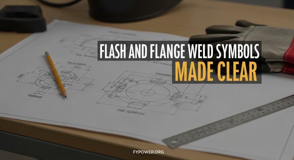
Flash and flange weld symbols are specialized graphical notations used on engineering drawings to specify light gauge metal joints where edges are flared or resistance-welded together. Unlike standard groove or fillet welds, these symbols communicate unique joining methods that require specific interpretation skills. Flash and flange weld symbols indicate light gauge metal welding joints where […]

Flash and Flange Weld Symbols: Complete Guide Read More »

Fillet Weld Symbols

Fillet Weld Symbols: Complete Guide to Reading Welding Symbols

Fillet weld symbols appear on technical drawings and blueprints wherever two pieces of metal need to be joined at an angle. These standardized notations communicate weld size, location, and configuration without words. The fillet weld symbol is a right triangle placed on the reference line with the perpendicular leg always positioned on the left side.

Fillet Weld Symbols: Complete Guide to Reading Welding Symbols Read More »

Arc Weld Symbols

Arc Weld Symbols: Complete Guide to Reading AWS A2.4 Welding Symbols

Arc weld symbols are the universal language of welding. They communicate weld requirements on blueprints without a single word. These symbols follow the AWS A2.4 standard. Every welder, fabricator, and inspector must understand them to work in the metal trades. I spent 15 years interpreting welding symbols in structural steel shops. I’ve seen what happens

Arc Weld Symbols: Complete Guide to Reading AWS A2.4 Welding Symbols Read More »

Scroll to Top