Arc weld symbols are the universal language of welding. They communicate weld requirements on blueprints without a single word. These symbols follow the AWS A2.4 standard. Every welder, fabricator, and inspector must understand them to work in the metal trades.
I spent 15 years interpreting welding symbols in structural steel shops. I’ve seen what happens when symbols get misread. Let me break down what these symbols mean and how to read them correctly.
Arc weld symbols are graphical representations on engineering drawings that specify the type, size, length, and location of welds needed. They follow the AWS A2.4 standard and consist of a reference line, arrow, tail, and various weld symbols.
- Key Standard: AWS A2.4:2020
- Components: Reference line, arrow, tail, weld symbol
- Purpose: Universal weld specification on drawings
Modern welding applications in manufacturing rely on precise symbol interpretation. A single misunderstood symbol can result in thousands of dollars of rework.
Anatomy of a Welding Symbol
Every welding symbol has a standard structure. AWS A2.4 defines exactly how these elements combine.
Quick Summary: A complete welding symbol has four main parts: the reference line (horizontal base), the arrow (points to weld location), the tail (contains specifications), and the weld symbol itself (type of weld required).
The reference line is the foundation. It’s always horizontal and acts as the anchor for all other information.
The Reference Line
The reference line is a horizontal line. All weld information attaches to this line.
Information above the line applies to the opposite side of the joint. Information below applies to the arrow side.
Think of the reference line as a divider. The arrow side weld goes below. The other side weld goes above.
The Arrow and Arrow Side
The arrow connects the reference line to the weld joint. It points specifically to where the weld happens.
The side of the joint the arrow points to is called the “arrow side.” The opposite side is the “other side.”
This distinction matters. Arrow side symbols go below the reference line. Other side symbols go above.
The Tail
The tail extends from the opposite end of the reference line. It contains supplementary information.
Common tail data includes welding process references, specification numbers, or special instructions.
When no special information is needed, the tail can be omitted entirely.
Dimension Locations
Weld dimensions follow specific positions on the reference line.
| Location | Information |
|---|---|
| Left of symbol | Weld size (leg size for fillet, depth for groove) |
| Right of symbol | Weld length and spacing (for intermittent welds) |
| Above symbol | Root opening, groove angle, finish method |
Basic Weld Types and Their Symbols
AWS A2.4 defines specific symbols for each weld type. Let’s cover the most common ones.
Fillet Weld Symbols
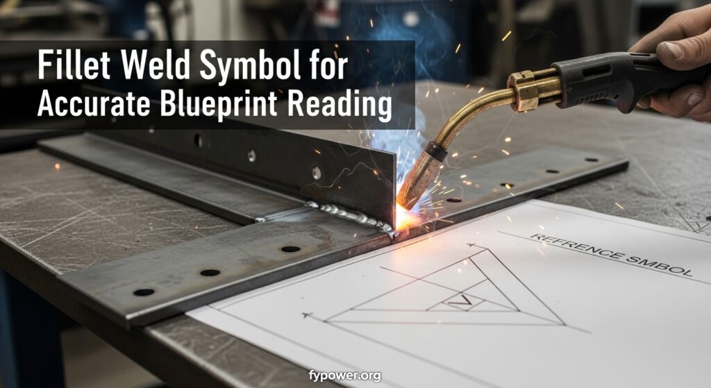
The fillet weld symbol is a triangle drawn against the reference line. It’s the most common weld in fabrication.
Fillet welds join two surfaces at approximately 90 degrees. Think of T-joints, lap joints, and corner joints.
Fillet Weld: A weld of approximately triangular cross-section joining two surfaces approximately at right angles in a lap joint, T-joint, or corner joint.
The triangle points toward the reference line. The size (leg length) appears to the left of the symbol.
A typical fillet symbol might show “1/4” to the left. This means a 1/4-inch leg fillet weld.
Groove Weld Symbols
Groove welds have multiple symbol variations based on joint preparation.
| Weld Type | Symbol Shape | Common Use |
|---|---|---|
| Square Groove | Two vertical lines (| |) | Thin material butt joints |
| V-Groove | V-shape pointing to reference line | Medium thickness butt joints |
| Bevel Groove | Single vertical line with V on one side | When only one side can be beveled |
| U-Groove | U-shape with rounded bottom | Thick material requiring less filler |
| J-Groove | Half U-shape | Single-sided access on thick material |
| Flare-V Groove | V with outward curved sides | Round-to-round or round-to-flat joints |
Groove weld dimensions include root opening, groove angle, and depth of preparation. These appear above the symbol.
Plug and Slot Welds
Plug weld symbols look like a rectangle. Slot weld symbols show a rectangle with an extended bottom.
Plug welds go through one member into another. Slot welds are elongated holes that get filled.
These are common in structural applications where you can’t access the back side for a standard weld.
Spot and Seam Welds
Spot weld symbols use a circle. Seam welds show a circle with a horizontal line through it.
These are resistance welding processes. They’re common in automotive and sheet metal applications.
Supplementary Welding Symbols
Beyond basic weld types, AWS A2.4 includes supplementary symbols that modify the weld requirements.
Weld-All-Around Symbol
A circle at the junction of arrow and reference line indicates weld all around.
This means the weld continues completely around the joint. Not just the visible portion.
I’ve seen fabricators miss this symbol and only weld what they see. The inspector catches it every time.
Weld All Around: A symbol (circle) indicating welding is to be performed all around a joint, even where the joint changes direction or extends beyond the visible drawing area.
Field Weld Symbol
A flag at the junction of arrow and reference line indicates field welding.
Field welds happen at the job site, not the fabrication shop. They require different procedures and coordination.
Shop welds are controlled and efficient. Field welds introduce weather, position, and access challenges.
Contour Symbols
Contour symbols indicate the desired weld surface finish after welding.
| Contour Symbol | Meaning |
|---|---|
| Straight line (-) | Flush surface without machining |
| Convex arc (~) | Rounded convex surface |
| Concave arc (n) | Rounded concave surface |
Finish Symbols
Letters above the contour symbol indicate the finishing method required.
- C – Chipping
- G – Grinding
- M – Machining
- R – Rolling
- H – Hammering
- P – Planishing
These symbols communicate post-weld requirements directly on the drawing.
How to Read Welding Symbols Step by Step?
Reading welding symbols systematically prevents errors. I’ve taught this process to dozens of apprentices.
Quick Summary: Read welding symbols by starting at the arrow (identifies weld location), then check the reference line (arrow side vs other side), note the weld symbol (weld type), read dimensions left to right, and check for supplementary symbols above or below.
Step 1: Identify the Arrow Side
Start where the arrow points. This is the arrow side of the joint.
Everything below the reference line applies to this side.
Step 2: Check for Other Side Welds
Look above the reference line. Any symbol here applies to the other side.
Symbols on both sides mean welding from both sides is required.
Step 3: Identify the Weld Type
The shape against the reference line tells you the weld type.
Triangle equals fillet. Square equals groove. Circle equals plug/slot or spot.
Step 4: Read the Dimensions
Read from left to right along the reference line.
Left of the symbol is weld size. Right of the symbol is length and spacing.
Step 5: Check Above and Below
Information above the reference line affects the other side.
Information below affects the arrow side.
Step 6: Look for Supplementary Symbols
Check the tail for process specifications.
Look for the flag (field weld) or circle (weld all around) at the arrow junction.
Multiple Reference Lines
Complex welds use multiple reference lines. AWS A2.4:2020 clarified this practice.
The reference line closest to the arrow indicates the first operation.
Subsequent lines show sequence operations. Think backing weld followed by finish weld.
Sequence matters in welding. Different processes have different preheat and interpass requirements.
Common Welding Symbol Mistakes to Avoid
I’ve seen these mistakes cause real problems in fabrication shops.
Confusing arrow side and other side is the most common error. The rule is simple: below is arrow side, above is other side.
Missing the weld-all-around symbol happens frequently. The circle at the junction means weld completely around the joint.
Ignoring the field weld flag is expensive. Shop procedures don’t apply to field welds. Different conditions require different approaches.
Interpreting Ambiguous Symbols
Sometimes symbols seem unclear. The AWS A2.4 standard provides guidance.
When in doubt, consult the original designer. Never assume what a symbol means.
Clarification prevents rework. I’ve seen a 10-minute phone call save three days of rework.
Reading Welding Symbols on Blueprints
Blueprint reading requires symbol fluency. Real fabrication drawings combine many weld symbols.
Structural steel drawings show connection details with complete welding symbols. Each connection might have multiple welds.
Pressure vessel drawings include weld symbols with procedure references. The tail often contains WPS numbers.
Certification Requirements
AWS Certified Welding Inspector exams test symbol interpretation extensively.
CWI certification requires reading complex symbols with multiple reference lines and supplementary information.
Symbol interpretation is also part of the Certified Welder performance tests. You must weld according to the symbol.
Related metalworking tools and techniques often use similar symbolic communication on technical drawings.
AWS A2.4:2020 Updates
The latest AWS A2.4 revision was released in 2020. It includes several important updates.
Fillet weld contour symbols were revised for clarity. The standard now provides more specific guidance on contour representation.
Multiple reference line applications received expanded explanations. The 2020 revision clarifies sequence welding notation.
Stay current with standards. Outdated symbol knowledge leads to non-compliant welds.
International Standards: ISO 2553
ISO 2553 is the international welding symbol standard. It differs from AWS A2.4 in several ways.
The arrow placement relative to the symbol differs between standards. ISO places the arrow on a specific side based on joint type.
Supplementary symbols also vary. Some symbols have different shapes or meanings in ISO 2553.
Global work means knowing both standards. International projects may use ISO notation.
Practical Tips for Symbol Mastery
Practice interpretation daily. Start with simple symbols and work up to complex ones.
Keep a reference chart handy. Even experienced welders consult charts occasionally.
Draw symbols from memory. If you can draw it, you understand it.
Quiz yourself with real blueprints. Try to interpret all symbols before checking the key.
Teach others. Explaining symbols to apprentices reinforces your own understanding.
Frequently Asked Questions
What are arc weld symbols?
Arc weld symbols are graphical representations used on engineering drawings to specify weld requirements. They follow the AWS A2.4 standard and communicate weld type, size, length, and location without words.
How do you read welding symbols?
Read welding symbols by starting at the arrow (weld location), checking the reference line position (below for arrow side, above for other side), identifying the weld symbol shape, reading dimensions left to right, and noting supplementary symbols like field weld or weld all around.
What is the AWS A2.4 standard?
AWS A2.4 is the American Welding Society standard that defines symbols for welding, brazing, and nondestructive examination. It’s the authoritative reference for welding symbols in North America and was most recently revised in 2020.
What is the difference between arrow side and other side?
The arrow side is the side of the joint that the arrow points to. Weld information below the reference line applies to the arrow side. The other side is the opposite side of the joint, and weld information above the reference line applies there.
What does the weld all around symbol mean?
The weld all around symbol is a circle placed at the junction of the arrow and reference line. It indicates that the weld must continue completely around the joint, even where the joint changes direction or extends beyond visible drawing limits.
What is the field weld symbol?
The field weld symbol is a flag placed at the junction of the arrow and reference line. It indicates that the weld must be performed at the installation site rather than in the fabrication shop, which often requires different procedures and considerations.
What do contour symbols mean in welding?
Contour symbols indicate the desired surface profile of the completed weld. A straight line means flush, a convex arc means rounded outward, and a concave arc means rounded inward. These may be accompanied by finish method letters.
Mastering arc weld symbols takes practice. Keep a reference chart handy and study real blueprints whenever possible. Your ability to interpret these symbols correctly directly impacts weld quality and job performance.
For those exploring plastic welding techniques or plastic fabrication methods, similar principles of symbolic communication apply in technical drawings across industries.