Category: Welding Education

  • Underwater Welding: Complete Career Guide 2026

    Underwater Welding: Complete Career Guide 2026

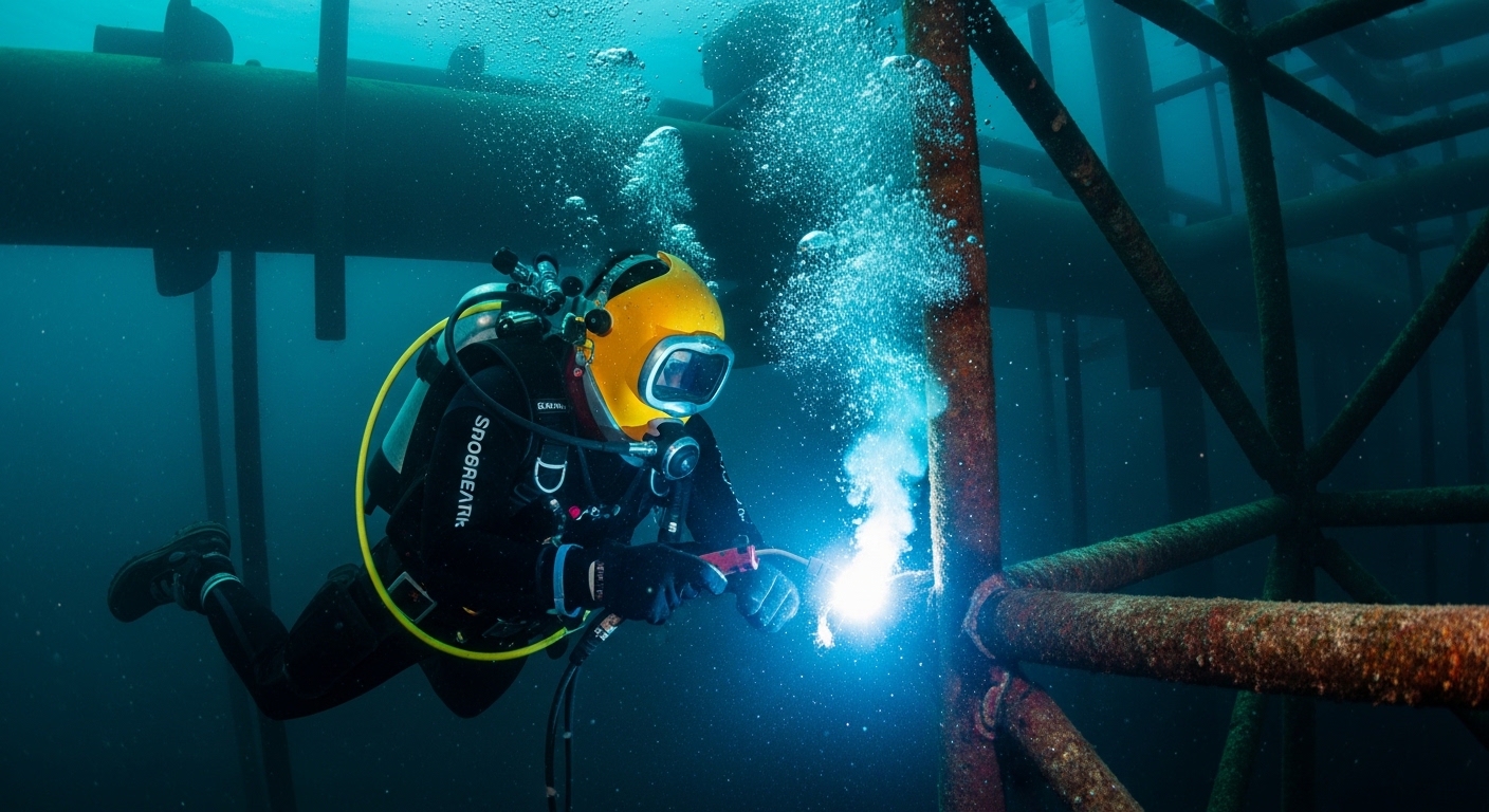
    Underwater welding is a specialized welding process performed in aquatic environments, typically used for repairing ships, pipelines, offshore oil platforms, bridges, dams, and other submerged infrastructure. This demanding trade combines commercial diving expertise with advanced welding technology, allowing critical repairs to be completed without removing structures from the water. The work offers high earning potential but requires extensive training and carries significant risks.

    I’ve spent years researching skilled trades, and underwater welding stands out as one of the most unique career paths in the industrial world. It’s not for everyone, but for those who thrive on adventure and technical challenges, it can be incredibly rewarding both financially and personally.

    What is Underwater Welding?

    Underwater welding involves joining metals beneath the water’s surface using specialized techniques and equipment. The process creates a strong metallurgical bond between metal components while working in an environment that naturally makes welding difficult, if not impossible, using conventional methods.

    Underwater Welding: A specialized fabrication process that joins metals in submerged environments using either wet welding (directly in water) or dry welding (in a sealed habitat). It requires dual certification in commercial diving and welding technology.

    The underwater welding market generates an estimated $3-5 billion annually, with 4-6% projected growth through 2026. This growth is driven by aging offshore infrastructure requiring maintenance, expansion of offshore wind energy projects, and increasing offshore oil and gas exploration in deeper waters.

    What makes this field unique is the dual expertise required. You’re not just a welder who can swim, or a diver who knows welding. You need mastery of both disciplines simultaneously, often in conditions where visibility is near zero and currents are working against you.

    Types of Underwater Welding Methods

    Underwater welding primarily uses two methods: wet welding and dry welding. Each approach has distinct advantages, limitations, and applications depending on the project requirements, depth, and environmental conditions.

    Quick Summary: Wet welding is performed directly in the water using special electrodes, making it faster and cheaper but with lower weld quality. Dry welding creates a dry chamber around the work area, producing high-quality welds similar to surface welding but requiring expensive equipment and longer setup times.

    Wet Welding

    Wet welding is performed directly in the water without any protective barrier around the work area. The welder uses specially designed waterproof electrodes that create a stable arc even when fully submerged.

    The process works by surrounding the welding arc with a gas bubble created as the electrode’s flux coating burns. This temporary bubble provides some protection from the water, though the weld is still influenced by the surrounding aquatic environment.

    Key characteristics of wet welding:

    • Uses shielded metal arc welding (SMAW) with waterproof electrodes
    • Can be performed at depths up to approximately 100 feet
    • Minimal equipment requirements compared to dry welding
    • Faster setup and execution for emergency repairs
    • Lower weld quality due to water contamination and rapid cooling

    Wet welding is commonly used for emergency repairs, temporary fixes, and situations where mobilizing dry welding equipment would be impractical or too costly. I’ve seen it used extensively for ship hull repairs, pipeline patches, and underwater structure stabilization.

    Dry Welding (Hyperbaric Welding)

    Dry welding, also called hyperbaric welding, creates a dry environment around the work area using a sealed chamber or habitat. This chamber is pressurized to match the surrounding water depth and displaces all water from the weld zone.

    The habitat allows the welder to work in essentially the same conditions as surface welding, resulting in much higher quality welds. Various habitat types exist, from small chambers that only cover the immediate weld area to large chambers that accommodate the welder’s entire upper body.

    Dry welding advantages include:

    • Weld quality comparable to surface welding
    • Can use multiple welding processes (SMAW, TIG, MIG, FCAW)
    • Better visibility and working conditions for the welder
    • Suitable for critical structural repairs
    • Can be performed at much greater depths with proper equipment

    The trade-off is cost and complexity. Dry welding requires significant equipment, surface support, and setup time. It’s typically reserved for critical infrastructure repairs where weld integrity is paramount, such as offshore platform legs, nuclear power plant components, and major pipeline repairs.

    AspectWet WeldingDry Welding
    EnvironmentPerformed directly in waterPerformed in sealed dry chamber
    Depth LimitUp to ~100 feet typicallyOver 1,000 feet with proper equipment
    Weld QualityLower quality, water contaminationHigh quality, similar to surface welding
    CostLower cost, minimal equipmentHigh cost, extensive equipment required
    Setup TimeQuick deployment, ideal for emergenciesLengthy setup, requires planning
    ApplicationsEmergency repairs, temporary fixesCritical structural repairs, permanent fixes

    Equipment Used in Underwater Welding

    Underwater welding requires specialized equipment that combines commercial diving gear with welding technology. The equipment must withstand corrosive saltwater, high pressure, and electrical challenges unique to underwater environments.

    Welding Equipment

    The core welding equipment includes a DC welding power supply specifically designed for underwater use, waterproof welding electrodes (for wet welding), and a welding stinger (electrode holder). The power supply must be carefully isolated and grounded to prevent electric shock hazards.

    For wet welding, electrodes feature special waterproof coatings and flux formulations designed to create a stable gas bubble even when submerged. These electrodes are typically thicker and more robust than surface welding electrodes.

    Dry welding systems may include standard welding equipment modified for hyperbaric conditions, including TIG (GTAW) and MIG (GMAW) setups that operate within the pressurized habitat.

    Diving Equipment

    Commercial diving gear for underwater welders typically includes surface-supplied diving equipment rather than SCUBA. Surface-supplied systems provide breathing gas through an umbilical cord from the surface, allowing for indefinite dive times and direct communication with the surface team.

    The diving helmet is a critical piece of equipment, providing head protection, communication systems, and breathing gas delivery. For cold water work, welders use hot water suits that circulate warm water from surface heaters throughout the suit.

    Safety and Support Equipment

    Safety equipment includes diving knives for emergency entanglement situations, emergency gas supplies ( bailout bottles), and comprehensive diving computers that monitor depth, bottom time, and decompression requirements.

    Surface support equipment includes decompression chambers for treating decompression sickness if it occurs, gas mixing systems for specialized breathing mixtures, and lifting equipment for heavy underwater components.

    Training and Certification Requirements

    Becoming an underwater welder requires significant investment in both time and money. The career path typically takes 2-4 years from start to employment, with total training costs ranging from $10,000 to $30,000 or more.

    Welding Certification

    Before considering underwater welding, you need a solid foundation in surface welding. Most underwater welding programs require applicants to already have welding experience or complete a foundational welding program first.

    The American Welding Society (AWS) offers certification for underwater welders through their D3.6 specification, which sets the standards for underwater welding procedures and qualification. This certification is widely recognized in the industry and demonstrates that you’ve met specific competency requirements.

    I’ve found that successful underwater welders typically start with 6-12 months of surface welding experience before pursuing their underwater specialization. This foundation is crucial for understanding the fundamental principles that become much more challenging underwater.

    Commercial Diving Certification

    Commercial diving certification is a separate and equally important requirement. The Association of Diving Contractors International (ADCI) sets the standards for commercial diver certification in the United States.

    Commercial diving programs typically run 6-12 months and cover diving physics, physiology, equipment operation, emergency procedures, and underwater work techniques. Tuition for these programs ranges from $15,000 to $25,000 for comprehensive training.

    Key certifications include:

    • Commercial Diver Certification (ADCI)
    • Medical fitness certification (annual diving physical required)
    • First aid, CPR, and emergency oxygen administration
    • Diver Medic Technician (advanced certification)
    • Specialized certifications for saturation diving (advanced career level)

    Underwater Welding Programs

    Several specialized schools offer combined underwater welding training, including Santa Barbara City College’s Marine Diving Technology program and Tulsa Welding School’s underwater welding program. These programs typically require welding experience as a prerequisite and focus on the specific techniques and safety protocols for underwater welding.

    Program duration ranges from a few weeks for advanced courses to 9-12 months for comprehensive programs that include both diving and welding certification.

    Underwater Welding Salary and Career Outlook

    Underwater welding salaries vary widely based on factors including experience level, certifications, geographic location, project type, and whether you work offshore or inland. The high salaries often cited in media represent top earners working in demanding offshore conditions, not typical starting salaries.

    Experience LevelAnnual Salary RangeKey Factors
    Entry Level (0-2 years)$50,000 – $80,000Basic certifications, inland projects, trainee positions
    Mid-Level (2-5 years)$80,000 – $120,000Multiple certifications, mixed projects, reliability
    Experienced (5-10 years)$120,000 – $180,000Advanced skills, supervisory roles, offshore work
    Top Earners (10+ years)$180,000 – $300,000+Saturation diving, hazardous conditions, union rates

    Salary Factors

    Several factors significantly affect earning potential in this field:

    Offshore vs. Inland: Offshore work, particularly in the oil and gas industry, typically pays significantly more than inland work. However, offshore jobs require extended time away from home (often 2-4 weeks at a time) and involve more challenging conditions.

    Certification Level: Divers with saturation diving certification can work at greater depths and command premium pay rates. Similarly, welders with advanced AWS certifications and specialized skills (such as nuclear plant welding) earn more.

    Union Membership: Union positions typically offer better pay, benefits, and working conditions. However, union jobs can be more difficult to obtain and may require connections or seniority.

    Geographic Location: Regions with high offshore activity such as Louisiana, Texas, California, and the Gulf of Mexico typically offer more opportunities and higher pay. International locations like the North Sea and Middle East also offer premium rates for experienced divers.

    Job Outlook

    The job outlook for underwater welders is mixed. While the field faces challenges from an aging workforce and high training barriers, growing offshore wind energy development and aging infrastructure requiring maintenance create ongoing demand.

    Industry projections show 4-6% annual growth through 2026, driven primarily by offshore energy expansion and infrastructure maintenance needs. However, competition for entry-level positions remains fierce, with many qualified candidates competing for limited openings.

    Industries That Hire Underwater Welders

    Underwater welders work across multiple industries, each with different working conditions, pay scales, and job requirements. Understanding these industries helps career seekers target their training and job search effectively.

    Offshore Oil and Gas

    The offshore oil and gas industry is the largest employer of underwater welders, particularly in the Gulf of Mexico, North Sea, and offshore regions worldwide. Work includes platform construction, maintenance, repair, and decommissioning.

    Offshore work offers the highest salaries but also involves the most demanding conditions. Divers typically work 2-4 week hitches living on platforms or vessels, with 12-hour shifts being common. Weather frequently interrupts work schedules.

    Shipping and Maritime

    Shipyards and ports employ underwater welders for hull repairs, propeller work, rudder repairs, and underwater ship maintenance. This work tends to be more consistent than offshore oil work and offers more predictable schedules.

    Major ports such as Houston, New Orleans, Los Angeles, and Norfolk provide steady employment for underwater welders specializing in maritime applications.

    Infrastructure and Civil Engineering

    Bridges, dams, locks, and underwater infrastructure require regular inspection and repair. Inland underwater welding jobs in this sector offer more stability and predictable schedules compared to offshore work, though typically at lower pay rates.

    Government agencies and civil engineering firms employ underwater welders for infrastructure maintenance projects across the country’s waterways.

    Nuclear Power Plants

    Nuclear power plants employ underwater welders for specialized maintenance and repair work in cooling systems and submerged components. These positions require additional certifications and rigorous security clearances but offer excellent pay and working conditions.

    Nuclear plant welding is considered one of the most desirable niches within underwater welding due to the controlled environment and high pay rates.

    Salvage and Recovery

    Marine salvage companies employ underwater welders for vessel salvage, cargo recovery, and emergency underwater repairs. This work can be unpredictable and exciting but offers less consistent employment than other sectors.

    Safety Risks and How They’re Managed

    Underwater welding carries significant risks that are managed through rigorous training, safety protocols, and equipment standards. While popular media often exaggerates the dangers, this career does involve real hazards that must be taken seriously.

    Electric Shock Hazards

    Welding underwater creates obvious electrical hazards. The risk is managed through specialized equipment design, including isolated welding power supplies, carefully grounded systems, and DC current (which is safer than AC underwater).

    All welding equipment must be specifically rated for underwater use, and divers follow strict procedures for electrode handling and welding operations to minimize shock risks.

    Decompression Sickness

    Also known as “the bends,” decompression sickness occurs when dissolved gases form bubbles in the bloodstream during ascent. This potentially life-threatening condition is managed through strict dive table adherence, controlled ascent rates, and surface decompression chambers for treatment.

    Commercial divers use specialized breathing gas mixtures and follow precise decompression schedules based on depth and bottom time. Safety stops during ascent allow the body to gradually eliminate absorbed gases.

    Environmental Hazards

    Cold water poses hypothermia risks, managed through hot water suits and heating systems. Poor visibility conditions require tactile welding techniques and extensive training. Strong currents create physical challenges and require careful dive planning.

    Marine life encounters are rare but can occur, making situational awareness important. Divers also face risks from underwater structures and debris.

    Myth vs. Reality: The Death Rate

    A common myth suggests underwater welders have an average life expectancy of only 50 years or a 50% death rate. These claims are false and not supported by actual data. With proper safety protocols and training, underwater welders have normal life expectancies.

    The actual risks are comparable to other dangerous professions such as commercial fishing, logging, or structural ironwork. Industry safety standards and regulations have dramatically improved safety outcomes over the past decades.

    Pros and Cons of an Underwater Welding Career

    Before investing in underwater welding training, it’s important to consider both the advantages and disadvantages of this career path. The reality often differs from the glamorous portrayals in media.

    Pros

    • High earning potential: Top earners can make $200,000+ annually, especially with offshore and saturation diving work
    • Unique and exciting work: No two days are the same, and the work offers adventure and challenge
    • Job security: Specialized skills create steady demand, particularly in offshore energy and infrastructure
    • Quick career path: Can enter the field in 2-4 years compared to many careers requiring 4+ year degrees
    • Travel opportunities: Work can take you to interesting locations around the world
    • Respect and recognition: The field commands respect due to the difficulty and danger of the work

    Cons

    • High training costs: $10,000-$30,000+ for required certifications with no guaranteed job placement
    • Time away from home: Offshore work can mean weeks away from family and friends
    • Physical demands: The work is physically taxing and career longevity is limited (most retire by 45-50)
    • Safety risks: Real dangers exist despite safety protocols and equipment
    • Inconsistent work: Feast or famine cycles with periods of unemployment between projects
    • Limited geographic options: Jobs are concentrated in coastal areas and specific inland locations
    • Difficulty entering the field: Competition for entry-level positions is fierce despite high costs

    How to Become an Underwater Welder

    If you’re considering this career, here’s the realistic path to entering the field based on industry practices and successful career trajectories.

    Quick Summary: Becoming an underwater welder typically takes 2-4 years and requires training in both welding and commercial diving. The total investment ranges from $10,000 to $30,000, with entry-level salaries starting around $50,000-$80,000 annually. Success requires excellent physical fitness, willingness to travel, and tolerance for time away from home.

    1. Get your high school diploma or GED: This is the minimum educational requirement. Focus on math, science, and shop classes if available.
    2. Gain surface welding experience: Complete a welding program or apprentice for 6-12 months to build fundamental welding skills.
    3. Research and select a training program: Choose an ADCI-accredited commercial diving school with underwater welding specialization. Santa Barbara City College and Tulsa Welding School are well-regarded options.
    4. Secure financing: Training costs range from $15,000-$30,000. Explore scholarships, grants, and financial aid options.
    5. Complete commercial diving training: This 6-12 month program covers diving physics, equipment, and safety procedures.
    6. Obtain certifications: Get your ADCI commercial diver certification and AWS welding certification.
    7. Pass diving physical: You’ll need an annual medical examination to ensure fitness for diving.
    8. Seek entry-level positions: Start as a diver tender or apprentice. Entry-level jobs are competitive, so persistence is key.
    9. Build experience and specialize: As you gain experience, pursue advanced certifications and specializations to increase earning potential.

    I’ve seen successful underwater welders who started in their early 20s and were earning six-figure salaries within 5 years. I’ve also seen people spend $20,000 on training only to struggle to find that first job. The difference often comes down to networking, persistence, and being realistic about entry-level opportunities.

    Is Underwater Welding Right for You?

    This career appeals to a specific type of person. You’ll likely thrive in underwater welding if you enjoy hands-on technical work, don’t mind physical challenges, are comfortable with risk, and can handle extended time away from home.

    The ideal age to start is in your early to mid-20s when you’re physically fit and can handle the demands of training and entry-level work. Starting in your 30s is possible but more challenging, and starting after 40 is extremely difficult due to physical requirements and employer preferences.

    If you’re considering this career, talk to current underwater welders, visit commercial diving schools, and honestly assess your tolerance for risk, time away from home, and physical demands. The rewards can be significant, but so are the sacrifices.

    Frequently Asked Questions

    What is underwater welding?

    Underwater welding is a specialized welding process performed in aquatic environments using either wet welding (directly in water) or dry welding (in a sealed chamber). It’s used for repairing ships, pipelines, offshore platforms, bridges, dams, and other submerged infrastructure without removing structures from the water.

    How much do underwater welders make?

    Entry-level underwater welders typically earn $50,000-$80,000 annually. Mid-level divers with 2-5 years of experience make $80,000-$120,000. Experienced underwater welders can earn $120,000-$180,000, while top earners with saturation diving certification and extensive offshore experience can make $200,000-$300,000 or more per year.

    How long does it take to become an underwater welder?

    Becoming an underwater welder typically takes 2-4 years. This includes 6-12 months of surface welding experience, 6-12 months of commercial diving training, certification exams, and time finding an entry-level position. Some comprehensive programs can be completed in 18-24 months, but building experience and advancing your career takes additional years.

    Is underwater welding dangerous?

    Yes, underwater welding carries real risks including electric shock, decompression sickness, drowning, hypothermia, and physical hazards from working in challenging environments. However, with proper training, safety protocols, and equipment, the risks are managed effectively. The accident rate is comparable to other dangerous trades when safety procedures are followed.

    What is the difference between wet and dry underwater welding?

    Wet welding is performed directly in the water using special waterproof electrodes, making it faster and cheaper but producing lower quality welds. Dry welding creates a dry chamber around the work area, allowing for high-quality welds similar to surface welding but requiring expensive equipment and longer setup times. Dry welding is used for critical structural repairs while wet welding is often used for emergency repairs.

    What certifications do you need for underwater welding?

    You need both commercial diving certification (typically from the Association of Diving Contractors International) and welding certification (typically from the American Welding Society). Additional requirements include passing an annual diving physical, first aid and CPR certification, and often emergency oxygen administration certification. Advanced positions may require Diver Medic Technician certification or saturation diving certification.

    What is the life expectancy of an underwater welder?

    Despite common myths claiming underwater welders have short life expectancies, the reality is that with proper safety protocols and equipment, underwater welders have normal life expectancies similar to the general population. The 50% death rate and life expectancy of 50 years are myths not supported by actual data. Safety standards have dramatically improved outcomes over recent decades.

    Where do underwater welders work?

    Underwater welders work in coastal regions with offshore activity including Louisiana, Texas, California, Florida, and Alaska. International opportunities exist in the North Sea, Middle East, and Asia-Pacific regions. Work environments include offshore oil platforms, shipping ports and shipyards, bridge and dam sites, pipeline routes, nuclear power plants, and marine salvage operations worldwide.

  • Flash and Flange Weld Symbols: Complete Guide

    Flash and Flange Weld Symbols: Complete Guide

    Flash and flange weld symbols are specialized graphical notations used on engineering drawings to specify light gauge metal joints where edges are flared or resistance-welded together. Unlike standard groove or fillet welds, these symbols communicate unique joining methods that require specific interpretation skills.

    I’ve spent years interpreting welding symbols in fabrication shops, and flash and flange welds are some of the most misunderstood symbols on drawings. These specialized welds appear in HVAC ductwork, automotive body panels, and sheet metal fabrication where thick welding beads would be impractical.

    Understanding these symbols correctly prevents costly fabrication errors. A misinterpreted flange weld symbol can lead to wrong joint preparation, resulting in weak connections that fail inspection or require expensive rework.

    Quick Reference: Flash and Flange Weld Symbols

    Quick Summary: There are four main flash and flange weld symbols: Edge Flange, Corner Flange, Flash Weld, and Upset Weld. Edge and corner flange welds use directional symbols placed on the reference line. Flash and upset weld symbols are centered on the reference line with no arrow or other side significance.

    Symbol TypeText RepresentationKey CharacteristicTypical Application
    Edge Flange< (perpendicular line with flare)Arrow side significanceSheet metal seams
    Corner FlangeL-shaped with flareArrow side significanceBox corners, ductwork
    Flash Weld|| (parallel lines centered)Centered on reference linePipe connections, rods
    Upset Weld= (equal sign centered)Centered on reference lineButt joints, tubing

    Understanding Welding Symbol Basics

    Before diving into flash and flange symbols specifically, you need to understand the foundation of all welding symbols. Every welding symbol shares common elements that convey specific information about the weld.

    Reference Line: The horizontal line that serves as the anchor for all welding symbol elements. It’s the foundation upon which the entire symbol is built.

    The reference line always appears horizontally on the drawing. The arrow extends from one end and points to the joint location. The other end typically has a tail where additional information can be specified.

    Symbol placement relative to the reference line determines which side of the joint gets welded. This is a fundamental concept that applies to most weld types, including edge and corner flange welds.

    Arrow Side vs. Other Side:

    1. Symbol below the reference line = weld on arrow side
    2. Symbol above the reference line = weld on other side
    3. Symbol on both sides = weld on both sides

    Arrow Side: The side of the joint that the arrow specifically points to. This is a critical concept for edge and corner flange welds, which have arrow side significance.

    Flash and upset welds are the exception to this placement rule. Their symbols are always centered on the reference line, meaning they have no arrow side or other side significance. I’ll explain why this matters in the flash and upset weld section below.

    Flange Weld Symbols: Edge and Corner

    Flange welds are used primarily for light gauge metal joints where the edges are flared or flanged to create the weld connection. These are common in sheet metal work, HVAC duct fabrication, and automotive body construction.

    There are two types of flange weld symbols you’ll encounter on drawings: edge flange and corner flange. Both have arrow side significance, meaning their placement on the reference line matters.

    Edge Flange Weld Symbol

    The edge flange weld symbol consists of a horizontal line (the reference line’s perpendicular element) with a flare or curve pointing away from the joint. The symbol resembles a right angle bracket with a curved or flared end.

    Text Diagram:

        Arrow points to joint
             |
             V
        _________________  (reference line)
             |
             |  (edge flange symbol below line = arrow side weld)
            (    (flare/curved element)
    

    Edge flange welds are used when joining two pieces of sheet metal along their edges, where one or both edges have been flanged outward. The flanged edges are then welded together to create a strong, flush connection.

    When edge flange symbols appear below the reference line:

    • The weld is made on the arrow side of the joint
    • The flanged edge is on the side the arrow points to
    • This is the most common placement for edge flange welds

    I frequently see edge flange welds in HVAC ductwork seams and automotive panel joints. The flanged edge creates a natural alignment feature that makes welding easier and more consistent.

    Corner Flange Weld Symbol

    The corner flange weld symbol is similar to the edge flange but shaped for corner applications. It appears as an L-shaped element with a flare or curve, indicating the metal is flanged at a corner joint.

    Text Diagram:

        Corner flange joint
             |
             V
        _________________  (reference line)
             |
             |_  (corner flange symbol below line)
                (flare/curved element)
    

    Corner flange welds join two pieces of light gauge metal at a corner where at least one piece has a flanged edge. This creates a boxed corner configuration common in enclosures, cabinets, and ductwork.

    Applications include:

    • HVAC duct corners and connections
    • Electrical enclosure corners
    • Sheet metal box construction
    • Automotive trunk and hood edges

    Both edge and corner flange weld symbols maintain arrow side significance. Their position relative to the reference line indicates which side receives the weld. This is different from flash and upset welds.

    Flash and Upset Weld Symbols

    Flash and upset welding are resistance welding processes that differ significantly from flange welding. These processes use electrical resistance, heat, and pressure to join metals without filler material.

    Flash Welding: A resistance welding process that creates a weld by rapidly heating the mating surfaces with an electric current, then forcing them together under pressure. The flashing action expels molten metal, creating a forged joint.

    Upset Welding: A resistance welding process similar to flash welding but without the flashing action. The parts are heated and then forged together under pressure in a single motion.

    What makes flash and upset weld symbols unique is their placement rule. Unlike other weld symbols, these are always centered on the reference line with no arrow side or other side significance.

    Flash Weld Symbol:

        Flash weld symbol (centered on reference line)
    
             |
        __||__||________  (reference line)
             flash symbol centered
    
             OR
    
             |
        ____||__||______  (reference line)
             flash symbol centered (same meaning either way)
    

    Upset Weld Symbol:

        Upset weld symbol (centered on reference line)
    
             |
        __==__==__________  (reference line)
            upset symbol centered
    
             OR
    
             |
        ____==__==________  (reference line)
            upset symbol centered (same meaning either way)
    

    Why Are These Symbols Centered?

    Flash and upset welding processes create symmetrical joints on both pieces being joined. Unlike flange welds where one side may be flanged differently, flash and upset welds affect both pieces equally throughout the entire cross-section.

    This is why AWS A2.4 and ANSI standards specify that flash and upset weld symbols must be centered on the reference line. There’s no “arrow side” or “other side” because the weld penetrates and affects both sides identically.

    I’ve seen fabricators confused by this convention. They look for arrow side information that doesn’t exist. Remember: if you see a weld symbol centered on the reference line, it’s a flash or upset weld, and the joint is welded completely through both pieces.

    Dimensions and Surface Contour Symbols

    Flash and flange weld symbols often include dimensional information and surface contour requirements. Understanding these supplementary symbols is essential for proper fabrication.

    Dimensioning Flange Welds

    Flange weld dimensions typically specify:

    • Height of flange: The vertical dimension of the flared edge
    • Radius at point of tangency: The curve radius where flange meets base metal
    • Root opening: Gap between pieces before welding

    Dimensions appear on the same side of the reference line as the weld symbol. For edge and corner flange welds, this means dimensions are placed below the reference line for arrow-side welds and above for other-side welds.

    Dimension Format Example

    Example: A dimension reading “0.12 (h) 0.25 (r)” indicates a flange height of 0.12 inches and a radius of 0.25 inches at the tangency point where the flange begins.

    Surface Contour Symbols

    Surface contour symbols indicate the desired finished appearance of the weld surface. These supplement the basic weld symbol with additional finishing requirements.

    Contour SymbolText RepresentationMeaning
    Flat– (straight line)Weld surface flush with base metal
    Convexarc (curved upward)Weld surface raised above base metal
    Concavecup (curved downward)Weld surface below base metal surface

    Contour symbols are placed above the weld symbol when no finish method is specified. If a specific finishing method (grinding, machining, etc.) is required, a letter is added below the contour symbol.

    I’ve seen many fabricators overlook contour symbols, leading to rejected parts. Always check for contour requirements before welding, especially for visible assemblies or parts that mate with other components.

    Step-by-Step: Reading a Flash or Flange Weld Symbol

    After teaching welding symbol interpretation to apprentices for years, I’ve developed a systematic approach that prevents errors. Follow these steps when reading any flash or flange weld symbol.

    Step-by-Step Reading Method

    Step 1: Identify the reference line and arrow direction. The arrow points to the joint location on the part.

    Step 2: Determine the weld symbol type. Is it an edge flange, corner flange, flash, or upset weld symbol?

    Step 3: Check symbol placement. Is it above, below, or centered on the reference line?

    Step 4: For flange welds: determine if weld is on arrow side (below line) or other side (above line). For flash/upset: placement doesn’t matter (centered).

    Step 5: Read all dimensions and specifications. Note size, length, spacing, and any special requirements.

    Step 6: Check for contour symbols and finishing requirements.

    Step 7: Review the tail for process specifications, reference standards, or supplementary notes.

    This systematic approach prevents the most common interpretation errors I see in fabrication shops. Rushing through symbol reading leads to mistakes that cost time and money to correct.

    Real-World Applications

    Understanding when and where flash and flange welds are used helps with symbol interpretation. These specialized welds appear in specific industries and applications.

    HVAC and Sheet Metal:

    Edge and corner flange welds are standard in HVAC duct fabrication. The flanged edges create self-aligning joints that weld quickly and consistently. I’ve seen miles of ductwork joined using corner flange welds in commercial construction projects.

    Automotive Industry:

    Flash welding connects automotive components like wheel rims, exhaust parts, and structural members. The process creates strong, consistent joints suitable for high-volume production. Many suspension components are flash-welded at the factory.

    Electrical Enclosures:

    Corner flange welds create sealed corners in electrical cabinets and control panels. The flanged edge design allows for consistent weld penetration and good appearance on visible enclosures.

    Pipe and Tubing:

    Flash welding joins pipes and tubing in applications requiring consistent, strong butt joints. The process creates a forged joint with properties matching the base metal.

    Common Mistakes When Reading Flash and Flange Weld Symbols

    After reviewing thousands of fabrication drawings and inspecting countless weldments, I’ve identified recurring interpretation errors. Avoiding these mistakes prevents rework and rejected parts.

    Mistake 1: Misinterpreting Arrow Side for Flash/Upset Welds

    Fabricators sometimes look for arrow side information on flash and upset weld symbols, but these symbols are always centered on the reference line. There is no arrow side or other side significance for flash and upset welds.

    Mistake 2: Confusing Flange with Flare Groove Symbols

    Flange weld symbols look similar to flare-bevel and flare-V groove symbols. The key difference is that flange welds are for light gauge metal with flanged edges, while flare groove welds are for heavier sections with grooved joints.

    Mistake 3: Ignoring Contour Requirements

    Surface contour symbols are frequently overlooked, leading to welds that don’t meet specifications. Always check for contour symbols above the weld symbol and any finishing methods specified.

    Mistake 4: Missing Dimensional Information

    Fabricators sometimes weld without checking all dimensions. Flange height and radius dimensions are critical for proper fit-up. Always verify all dimensional requirements before welding.

    Mistake 5: Not Checking Tail Information

    The tail of the welding symbol contains important information including welding process, specification references, and special requirements. Ignoring tail information leads to non-compliant welds.

    These mistakes are easily avoided with careful symbol reading and a systematic approach. Taking an extra minute to verify all symbol details prevents hours of rework.

    Frequently Asked Questions

    How is a flash weld indicated on the welding symbol?

    A flash weld is indicated by two parallel lines placed on and centered on the reference line. The symbol resembles the equals sign (=) positioned in the center of the horizontal reference line. Unlike most weld symbols, flash weld symbols have no arrow side or other side significance.

    What does flash mean in welding?

    Flash welding is a resistance welding process that joins metals by heating them with electric current until molten, then forcing them together under pressure. The flashing action expels impurities and creates a forged joint. The process produces strong, consistent welds without filler metal.

    Where are flange weld symbols placed on the reference line?

    Edge and corner flange weld symbols are placed either above or below the reference line to indicate other side or arrow side welds respectively. Unlike flash and upset welds, flange weld symbols have arrow side significance. Placement below the line means arrow side, above means other side.

    What is the difference between flash and upset welding?

    Flash welding creates a visible flashing action as molten metal is expelled from the joint before forging. Upset welding heats the parts without visible flashing, then forges them together in a single motion. Both use resistance heating and pressure, and both use centered symbols on the reference line.

    What are welding symbols used for?

    Welding symbols are graphical notations on engineering drawings that communicate weld requirements without extensive written notes. They specify weld type, size, length, location, and other requirements using standardized symbols. This system ensures clear communication between designers and welders per AWS and ANSI standards.

    Summary

    Flash and flange weld symbols communicate specialized joining methods for light gauge metal and resistance welding applications. Edge and corner flange welds use directional symbols with arrow side significance, while flash and upset welds are centered on the reference line.

    Understanding these symbols prevents fabrication errors and ensures proper joint preparation. The systematic reading method I’ve outlined helps you interpret symbols correctly every time. Reference AWS A2.4 and ANSI standards for complete symbol specifications.

    Practice reading symbols on actual drawings to build confidence. The more you work with these symbols, the more natural the interpretation becomes. Start with simple symbols and gradually work up to complex drawings with multiple weld types and specifications.

  • Fillet Weld Symbols: Complete Guide to Reading Welding Symbols

    Fillet Weld Symbols: Complete Guide to Reading Welding Symbols

    Fillet weld symbols appear on technical drawings and blueprints wherever two pieces of metal need to be joined at an angle. These standardized notations communicate weld size, location, and configuration without words.

    I’ve seen these symbols on everything from structural steel beams to automotive frames. Understanding these symbols correctly prevents costly mistakes.

    A welder I once worked with misread a 3/8-inch weld size as 1/4-inch, resulting in an entire batch of structural components being rejected. The cost of that mistake was three full days of rework and thousands of dollars in lost time.

    Anatomy of a Fillet Weld Symbol

    Quick Summary: Every fillet weld symbol consists of five main components: the reference line, arrow line, tail, weld symbol (triangle), and dimensions. Each element provides specific information about how the weld should be executed.

    A fillet weld symbol isn’t just a triangle. It’s a complete communication system that includes several elements working together.

    The Reference Line

    The reference line is the horizontal foundation of the entire welding symbol. Think of it as the anchor point for all other information.

    Reference Line: The horizontal line that forms the base of the welding symbol. All weld symbols, dimensions, and supplementary information are placed above, below, or on this line.

    This line divides the symbol into two critical zones: the arrow side (below the line) and the other side (above the line).

    The Arrow and Arrow Line

    The arrow extends from the reference line and points directly to the joint that requires welding. This connection removes any ambiguity about which joint gets the weld.

    In complex drawings with multiple joints, the arrow’s position is your definitive guide. I’ve seen confusion arise when welders assume rather than follow the arrow.

    The Tail

    The tail extends from the opposite end of the reference line and contains optional information. Not every symbol has a tail.

    When present, the tail typically references welding procedures, specifications, or other notes. You might see “WPS” or specification numbers like “AWS D1.1” here.

    The Fillet Weld Symbol (Triangle)

    The triangular symbol represents the fillet weld itself. The perpendicular leg always appears on the left side of the triangle.

    This triangle can appear above the reference line, below it, or on both sides. Its position tells you which side of the joint to weld.

    T-Joints
    Lap Joints
    Corner Joints

    Dimension Placement

    Dimensions follow specific rules based on their position relative to the weld symbol. The size (leg length) always appears to the left of the triangle.

    Length and pitch information appears to the right when specified. This consistent placement helps you read symbols quickly once you know the pattern.

    Reading Fillet Weld Dimensions

    Dimensions tell you the exact size and extent of the weld required. Reading them correctly is critical for meeting specifications.

    Weld Size (Leg Size)

    The weld size dimension appears to the left of the fillet weld symbol. This number represents the leg length of the triangular weld cross-section.

    For example, if you see “3/8” to the left of the triangle, the weld legs should each measure 3/8 inch. The weld throat will be approximately 0.707 times the leg size.

    Leg Size
    3/8 inch
    Throat (approx.)
    0.266 inch
    Formula
    Leg x 0.707

    Weld Length

    When a specific weld length is required, it appears to the right of the weld symbol. This dimension tells you the total length of the weld segment.

    If no length is specified, the weld should run the full length of the joint. This default rule catches many beginners off guard.

    Understanding Throat Measurements

    The throat is the distance from the weld root to the weld face, measured through the weld cross-section. Two throat measurements matter.

    Theoretical Throat: The distance from the root to the theoretical face of the weld, calculated as the leg size times 0.707 for equal-leg fillet welds.

    Engineers use theoretical throat for strength calculations. Inspectors measure actual throat to verify the weld meets specifications.

    I’ve seen projects delayed because welders focused on leg size while engineers specified throat requirements. Both measurements matter for different reasons.

    Arrow Side vs Other Side Explained

    This is the most common source of confusion for beginners. Getting it wrong means welding the wrong side of the joint.

    Arrow Side Welds

    When the fillet weld symbol appears below the reference line, the weld goes on the arrow side. This means the weld is placed on the side of the joint that the arrow points toward.

    Think of it this way: the arrow points to one side of the joint material. The symbol below the line says “weld this side.”

    Other Side Welds

    When the fillet weld symbol appears above the reference line, the weld goes on the opposite side from the arrow. The arrow still points to the joint, but the weld goes on the other side.

    This distinction matters most in T-joints and corner joints where welding on one side versus the other affects accessibility and appearance.

    Symbol PositionWeld LocationQuick Memory Trick
    Below reference lineArrow side“Same side as arrow”
    Above reference lineOther side“Opposite from arrow”
    Both sidesDouble fillet weld“Weld both sides”

    Double Fillet Welds

    When the triangle symbol appears both above and below the reference line, you need to weld both sides of the joint. This is called a double fillet weld.

    Double fillets provide symmetrical strength and are common in structural applications where balanced load distribution matters.

    Intermittent Fillet Welds

    Not all fillet welds run continuously. Intermittent welds consist of a series of weld segments with gaps between them.

    Chain Intermittent Welding

    Chain intermittent welds place segments directly opposite each other on both sides of the joint. The weld segments align in a chain-like pattern.

    Both sides of the joint have welds at the same positions. This creates a symmetrical pattern that’s easy to inspect and provides balanced strength.

    Staggered Intermittent Welding

    Staggered intermittent welds alternate the weld segments between sides. The welds on one side are positioned in the gaps of the opposite side.

    This pattern distributes stress more evenly across the joint. I’ve seen it used extensively in structural applications to reduce distortion while maintaining strength.

    Pitch vs Spacing: The Critical Difference

    This distinction trips up everyone at first. Pitch and spacing are NOT the same thing.

    Pitch: The center-to-center distance between adjacent weld segments. Pitch includes both the weld length and the gap between welds. If pitch is 4 inches and weld length is 2 inches, the gap is 2 inches.

    Spacing: The actual gap distance between weld segments. Spacing is the distance from the end of one weld to the start of the next.

    Confusing these two terms leads to incorrect weld placement. A welder on a forum once admitted to scrapping a 500-part batch because they misunderstood pitch as spacing.

    Remember: Pitch always equals weld length plus spacing. The dimension shown on drawings is almost always pitch, not spacing.

    MeasurementWhat It MeasuresOn Drawing
    Weld LengthLength of each weld segmentLeft of dash (e.g., 3-4)
    PitchCenter-to-center distanceRight of dash (e.g., 3-4)
    SpacingGap between weldsNot shown directly (calculate: pitch minus weld length)

    Supplementary Weld Symbols

    Additional symbols provide extra information about weld requirements. These supplementary symbols appear in combination with the basic fillet weld symbol.

    All-Around Symbol

    The all-around symbol is a circle that connects the arrow and reference line. It indicates the weld should be made completely around the joint.

    This symbol eliminates the need for multiple weld symbols on circular or perimeter welds. One symbol with the circle covers the entire joint.

    I’ve seen this on pipe connections, rectangular frames, and any application where continuous perimeter welding is required.

    Field Weld Symbol

    The field weld symbol is a small flag at the intersection of the reference line and arrow. It indicates the weld should be made at the installation site rather than in the fabrication shop.

    This distinction matters because shop welding and field welding require different procedures, equipment, and quality control measures.

    An inspector I know tells stories about expensive rework caused when welders missed field weld symbols and completed everything in the shop. The parts had to be disassembled and reassembled on site.

    Contour Symbols

    Contour symbols indicate the desired surface finish of the weld. These appear as lines above or below the fillet weld symbol.

    • Flat contour: A straight line indicates the weld face should be approximately flush
    • Convex contour: An arc curving outward indicates a raised, rounded weld face
    • Concave contour: An arc curving inward indicates a recessed weld face
    Flat (Flush)
    Convex (Raised)
    Concave (Recessed)

    Finish Method Symbols

    Letters following the contour symbol indicate the required finishing method:

    • C: Chipping
    • G: Grinding
    • H: Hammering
    • M: Machining
    • R: Rolling

    These finishing methods ensure the weld meets specific surface requirements. Grinding is most common for smooth surfaces, while chipping removes slag before additional passes.

    How to Read a Fillet Weld Symbol: Step-by-Step

    Reading fillet weld symbols systematically prevents mistakes. Follow this process every time.

    1. Identify the reference line: Find the horizontal line that serves as the foundation of the symbol.
    2. Follow the arrow: Trace the arrow to see which joint it points to. This removes ambiguity about location.
    3. Check symbol position: Is the triangle below the line (arrow side), above the line (other side), or both (double weld)?
    4. Read the size dimension: Look to the left of the triangle for leg size. This is your primary weld size.
    5. Check for length and pitch: Look to the right of the triangle for intermittent weld specifications.
    6. Identify supplementary symbols: Look for all-around circles, field weld flags, or contour symbols.
    7. Check the tail: Note any specification references or procedure notes.
    8. Verify with the drawing: Cross-reference your interpretation with other views and notes on the drawing.

    Reading Checklist

    Use this checklist when reading fillet weld symbols on actual drawings:

    CheckWhat to Look ForAction
    Weld sideSymbol above, below, or bothDetermine which side to weld
    Weld sizeDimension left of symbolSet leg length dimension
    Weld lengthDimension right of symbolMark weld segment length
    Intermittent patternDash notation (e.g., 3-4)Calculate pitch and spacing
    Supplementary symbolsCircle, flag, contour linesApply special requirements
    Tail notesTail with text or specsReview referenced procedures

    Common Mistakes When Reading Fillet Weld Symbols

    After reviewing inspection reports and forum discussions, I’ve identified the most common mistakes welders make when interpreting fillet weld symbols.

    Mistake 1: Confusing Arrow Side and Other Side

    This mistake causes welders to weld the wrong side of the joint entirely. The result is often complete part rejection.

    A Reddit user described making this exact error on an entire production run. The symbol showed welds on the other side, but they welded the arrow side instead.

    Mistake 2: Misreading Leg Size

    Reading the dimension to the right of the symbol instead of the left results in incorrect weld size. This common error compromises structural integrity.

    I’ve seen 1/4-inch welds specified but 3/8-inch welds made, and vice versa. Both errors cause problems but for different reasons.

    Mistake 3: Confusing Pitch and Spacing

    When intermittent welds are specified, misunderstanding pitch as spacing results in incorrectly placed weld segments.

    A welder on a forum shared how they calculated gaps using pitch values directly. The resulting welds didn’t meet specifications, and the entire assembly needed rework.

    Mistake 4: Missing Field Weld Symbols

    Overlooking the field weld flag means welding in the shop instead of at the installation site. This mistake creates expensive logistical problems.

    One fabricator had to disassemble shop-welded structures and reweld them in the field because the field weld symbol was missed during initial fabrication.

    Mistake 5: Ignoring Contour and Finish Symbols

    Skipping contour and finish requirements leads to rejected welds during inspection. The weld might be structurally sound but fail surface finish requirements.

    This matters most in applications where smooth surfaces are critical for appearance, fluid flow, or mechanical clearance.

    Pro Tip: Always take time to verify your interpretation against other drawing views and notes. A few minutes of verification can prevent hours of rework.

    Frequently Asked Questions

    What is the symbol for fillet weld?

    The fillet weld symbol is a right triangle placed on the reference line with the perpendicular leg always positioned on the left side. This triangle appears either above or below the horizontal reference line to indicate which side of the joint requires welding.

    How do you read a fillet weld symbol?

    Start by identifying the reference line and arrow. Check if the triangle is below the line (arrow side) or above (other side). Read the dimension to the left for weld size. Look to the right for length and pitch information. Finally, check for supplementary symbols like the all-around circle or field weld flag.

    What is the difference between arrow side and other side in fillet weld symbols?

    Arrow side means the weld is placed on the side of the joint that the arrow points toward, indicated by the symbol below the reference line. Other side means the weld is placed on the opposite side from the arrow, indicated by the symbol above the reference line. When the symbol appears on both sides, you need a double fillet weld.

    What is pitch in intermittent fillet welds?

    Pitch is the center-to-center distance between adjacent weld segments in an intermittent weld pattern. It includes both the weld length and the gap between welds. For example, a 3-4 designation means 3-inch weld segments with 4-inch pitch, resulting in 1-inch gaps between welds.

    What are the parts of a fillet weld symbol?

    The main components are the reference line (horizontal base), arrow line (points to the joint), tail (contains optional notes), weld symbol (the triangle), and dimensions. Each element provides specific information about weld location, size, length, and special requirements.

    What does the circle symbol mean in welding?

    The circle that connects the arrow and reference line is the all-around symbol. It indicates the weld should be made continuously around the entire joint. This symbol eliminates the need for multiple weld symbols when specifying perimeter welds on circular or closed joints.


  • Arc Weld Symbols: Complete Guide to Reading AWS A2.4 Welding Symbols

    Arc Weld Symbols: Complete Guide to Reading AWS A2.4 Welding Symbols

    Arc weld symbols are the universal language of welding. They communicate weld requirements on blueprints without a single word. These symbols follow the AWS A2.4 standard. Every welder, fabricator, and inspector must understand them to work in the metal trades.

    I spent 15 years interpreting welding symbols in structural steel shops. I’ve seen what happens when symbols get misread. Let me break down what these symbols mean and how to read them correctly.

    Modern welding applications in manufacturing rely on precise symbol interpretation. A single misunderstood symbol can result in thousands of dollars of rework.

    Anatomy of a Welding Symbol

    Every welding symbol has a standard structure. AWS A2.4 defines exactly how these elements combine.

    Quick Summary: A complete welding symbol has four main parts: the reference line (horizontal base), the arrow (points to weld location), the tail (contains specifications), and the weld symbol itself (type of weld required).

    The reference line is the foundation. It’s always horizontal and acts as the anchor for all other information.

    The Reference Line

    The reference line is a horizontal line. All weld information attaches to this line.

    Information above the line applies to the opposite side of the joint. Information below applies to the arrow side.

    Think of the reference line as a divider. The arrow side weld goes below. The other side weld goes above.

    The Arrow and Arrow Side

    The arrow connects the reference line to the weld joint. It points specifically to where the weld happens.

    The side of the joint the arrow points to is called the “arrow side.” The opposite side is the “other side.”

    This distinction matters. Arrow side symbols go below the reference line. Other side symbols go above.

    The Tail

    The tail extends from the opposite end of the reference line. It contains supplementary information.

    Common tail data includes welding process references, specification numbers, or special instructions.

    When no special information is needed, the tail can be omitted entirely.

    Dimension Locations

    Weld dimensions follow specific positions on the reference line.

    LocationInformation
    Left of symbolWeld size (leg size for fillet, depth for groove)
    Right of symbolWeld length and spacing (for intermittent welds)
    Above symbolRoot opening, groove angle, finish method

    Basic Weld Types and Their Symbols

    AWS A2.4 defines specific symbols for each weld type. Let’s cover the most common ones.

    Fillet Weld Symbols

    The fillet weld symbol is a triangle drawn against the reference line. It’s the most common weld in fabrication.

    Fillet welds join two surfaces at approximately 90 degrees. Think of T-joints, lap joints, and corner joints.

    Fillet Weld: A weld of approximately triangular cross-section joining two surfaces approximately at right angles in a lap joint, T-joint, or corner joint.

    The triangle points toward the reference line. The size (leg length) appears to the left of the symbol.

    A typical fillet symbol might show “1/4” to the left. This means a 1/4-inch leg fillet weld.

    Groove Weld Symbols

    Groove welds have multiple symbol variations based on joint preparation.

    Weld TypeSymbol ShapeCommon Use
    Square GrooveTwo vertical lines (| |)Thin material butt joints
    V-GrooveV-shape pointing to reference lineMedium thickness butt joints
    Bevel GrooveSingle vertical line with V on one sideWhen only one side can be beveled
    U-GrooveU-shape with rounded bottomThick material requiring less filler
    J-GrooveHalf U-shapeSingle-sided access on thick material
    Flare-V GrooveV with outward curved sidesRound-to-round or round-to-flat joints

    Groove weld dimensions include root opening, groove angle, and depth of preparation. These appear above the symbol.

    Plug and Slot Welds

    Plug weld symbols look like a rectangle. Slot weld symbols show a rectangle with an extended bottom.

    Plug welds go through one member into another. Slot welds are elongated holes that get filled.

    These are common in structural applications where you can’t access the back side for a standard weld.

    Spot and Seam Welds

    Spot weld symbols use a circle. Seam welds show a circle with a horizontal line through it.

    These are resistance welding processes. They’re common in automotive and sheet metal applications.

    Supplementary Welding Symbols

    Beyond basic weld types, AWS A2.4 includes supplementary symbols that modify the weld requirements.

    Weld-All-Around Symbol

    A circle at the junction of arrow and reference line indicates weld all around.

    This means the weld continues completely around the joint. Not just the visible portion.

    I’ve seen fabricators miss this symbol and only weld what they see. The inspector catches it every time.

    Weld All Around: A symbol (circle) indicating welding is to be performed all around a joint, even where the joint changes direction or extends beyond the visible drawing area.

    Field Weld Symbol

    A flag at the junction of arrow and reference line indicates field welding.

    Field welds happen at the job site, not the fabrication shop. They require different procedures and coordination.

    Shop welds are controlled and efficient. Field welds introduce weather, position, and access challenges.

    Contour Symbols

    Contour symbols indicate the desired weld surface finish after welding.

    Contour SymbolMeaning
    Straight line (-)Flush surface without machining
    Convex arc (~)Rounded convex surface
    Concave arc (n)Rounded concave surface

    Finish Symbols

    Letters above the contour symbol indicate the finishing method required.

    • C – Chipping
    • G – Grinding
    • M – Machining
    • R – Rolling
    • H – Hammering
    • P – Planishing

    These symbols communicate post-weld requirements directly on the drawing.

    How to Read Welding Symbols Step by Step?

    Reading welding symbols systematically prevents errors. I’ve taught this process to dozens of apprentices.

    Quick Summary: Read welding symbols by starting at the arrow (identifies weld location), then check the reference line (arrow side vs other side), note the weld symbol (weld type), read dimensions left to right, and check for supplementary symbols above or below.

    Step 1: Identify the Arrow Side

    Start where the arrow points. This is the arrow side of the joint.

    Everything below the reference line applies to this side.

    Step 2: Check for Other Side Welds

    Look above the reference line. Any symbol here applies to the other side.

    Symbols on both sides mean welding from both sides is required.

    Step 3: Identify the Weld Type

    The shape against the reference line tells you the weld type.

    Triangle equals fillet. Square equals groove. Circle equals plug/slot or spot.

    Step 4: Read the Dimensions

    Read from left to right along the reference line.

    Left of the symbol is weld size. Right of the symbol is length and spacing.

    Step 5: Check Above and Below

    Information above the reference line affects the other side.

    Information below affects the arrow side.

    Step 6: Look for Supplementary Symbols

    Check the tail for process specifications.

    Look for the flag (field weld) or circle (weld all around) at the arrow junction.

    Multiple Reference Lines

    Complex welds use multiple reference lines. AWS A2.4:2020 clarified this practice.

    The reference line closest to the arrow indicates the first operation.

    Subsequent lines show sequence operations. Think backing weld followed by finish weld.

    Sequence matters in welding. Different processes have different preheat and interpass requirements.

    Common Welding Symbol Mistakes to Avoid

    I’ve seen these mistakes cause real problems in fabrication shops.

    Confusing arrow side and other side is the most common error. The rule is simple: below is arrow side, above is other side.

    Missing the weld-all-around symbol happens frequently. The circle at the junction means weld completely around the joint.

    Ignoring the field weld flag is expensive. Shop procedures don’t apply to field welds. Different conditions require different approaches.

    Interpreting Ambiguous Symbols

    Sometimes symbols seem unclear. The AWS A2.4 standard provides guidance.

    When in doubt, consult the original designer. Never assume what a symbol means.

    Clarification prevents rework. I’ve seen a 10-minute phone call save three days of rework.

    Reading Welding Symbols on Blueprints

    Blueprint reading requires symbol fluency. Real fabrication drawings combine many weld symbols.

    Structural steel drawings show connection details with complete welding symbols. Each connection might have multiple welds.

    Pressure vessel drawings include weld symbols with procedure references. The tail often contains WPS numbers.

    Certification Requirements

    AWS Certified Welding Inspector exams test symbol interpretation extensively.

    CWI certification requires reading complex symbols with multiple reference lines and supplementary information.

    Symbol interpretation is also part of the Certified Welder performance tests. You must weld according to the symbol.

    Related metalworking tools and techniques often use similar symbolic communication on technical drawings.

    AWS A2.4:2020 Updates

    The latest AWS A2.4 revision was released in 2020. It includes several important updates.

    Fillet weld contour symbols were revised for clarity. The standard now provides more specific guidance on contour representation.

    Multiple reference line applications received expanded explanations. The 2020 revision clarifies sequence welding notation.

    Stay current with standards. Outdated symbol knowledge leads to non-compliant welds.

    International Standards: ISO 2553

    ISO 2553 is the international welding symbol standard. It differs from AWS A2.4 in several ways.

    The arrow placement relative to the symbol differs between standards. ISO places the arrow on a specific side based on joint type.

    Supplementary symbols also vary. Some symbols have different shapes or meanings in ISO 2553.

    Global work means knowing both standards. International projects may use ISO notation.

    Practical Tips for Symbol Mastery

    Practice interpretation daily. Start with simple symbols and work up to complex ones.

    Keep a reference chart handy. Even experienced welders consult charts occasionally.

    Draw symbols from memory. If you can draw it, you understand it.

    Quiz yourself with real blueprints. Try to interpret all symbols before checking the key.

    Teach others. Explaining symbols to apprentices reinforces your own understanding.

    Frequently Asked Questions

    What are arc weld symbols?

    Arc weld symbols are graphical representations used on engineering drawings to specify weld requirements. They follow the AWS A2.4 standard and communicate weld type, size, length, and location without words.

    How do you read welding symbols?

    Read welding symbols by starting at the arrow (weld location), checking the reference line position (below for arrow side, above for other side), identifying the weld symbol shape, reading dimensions left to right, and noting supplementary symbols like field weld or weld all around.

    What is the AWS A2.4 standard?

    AWS A2.4 is the American Welding Society standard that defines symbols for welding, brazing, and nondestructive examination. It’s the authoritative reference for welding symbols in North America and was most recently revised in 2020.

    What is the difference between arrow side and other side?

    The arrow side is the side of the joint that the arrow points to. Weld information below the reference line applies to the arrow side. The other side is the opposite side of the joint, and weld information above the reference line applies there.

    What does the weld all around symbol mean?

    The weld all around symbol is a circle placed at the junction of the arrow and reference line. It indicates that the weld must continue completely around the joint, even where the joint changes direction or extends beyond visible drawing limits.

    What is the field weld symbol?

    The field weld symbol is a flag placed at the junction of the arrow and reference line. It indicates that the weld must be performed at the installation site rather than in the fabrication shop, which often requires different procedures and considerations.

    What do contour symbols mean in welding?

    Contour symbols indicate the desired surface profile of the completed weld. A straight line means flush, a convex arc means rounded outward, and a concave arc means rounded inward. These may be accompanied by finish method letters.

    Mastering arc weld symbols takes practice. Keep a reference chart handy and study real blueprints whenever possible. Your ability to interpret these symbols correctly directly impacts weld quality and job performance.

    For those exploring plastic welding techniques or plastic fabrication methods, similar principles of symbolic communication apply in technical drawings across industries.


  • SMAW Welding Basics, Techniques & Uses Explained 2026

    SMAW Welding Basics, Techniques & Uses Explained 2026

    SMAW welding, or Shielded Metal Arc Welding, is the process that started my welding journey fifteen years ago. I still remember my first arc strike, the sudden flash, and the satisfying sizzle of a properly running bead. SMAW, commonly called stick welding, remains one of the most versatile and widely used welding processes in the world.

    SMAW stands for Shielded Metal Arc Welding. It is a manual arc welding process that uses a consumable, flux-coated electrode to create an electric arc between the electrode and the workpiece. The intense heat from the arc (over 9,000 degrees F) melts both the base metal and the electrode, forming a weld pool. As the weld cools, the flux coating creates a protective slag that shields the molten metal from atmospheric contamination.

    After teaching welding classes to over 200 students and working in fabrication shops across three states, I have seen SMAW prove itself time and again. This guide covers everything you need to know about stick welding, from the basic process to advanced techniques.

    How SMAW Welding Works?

    Quick Summary: SMAW works by creating an electric arc between a flux-coated electrode and the metal being welded. The arc melts both metals while the flux coating vaporizes into shielding gas and forms protective slag. This simple yet effective process requires no external gas, making it ideal for outdoor and field work.

    Understanding how SMAW works helps you make better welds. The process relies on three simultaneous actions: arc creation, metal deposition, and shielding.

    When you strike an arc, electrical current flows from the power source through the electrode holder, into the electrode, and jumps across the gap to the workpiece. This electric arc generates extreme heat that melts the end of the electrode and the base metal beneath it. As you maintain the arc and move along the joint, the molten electrode fills the gap creating the weld.

    Meanwhile, the flux coating performs two critical functions. First, it vaporizes into protective gases that shield the weld pool from oxygen and nitrogen in the air. Second, it melts and floats to the surface, forming slag that protects the cooling weld from contamination until you chip it away.

    The entire process happens in seconds. A typical 1/8 inch electrode consumes at about 2-3 inches per minute at 125 amps. In my experience welding pressure vessel pipe, I learned that reading the arc sound and rhythm matters more than watching the puddle. A steady, crackling sound like bacon frying indicates proper amperage and arc length.

    SMAW uses either AC (alternating current) or DC (direct current) power sources. DC provides smoother arc operation and easier starting, while AC works better for magnetized materials. Most modern stick welders offer both options, giving you flexibility for different applications.

    SMAW Equipment and Components

    Setting up your first SMAW station requires minimal investment compared to other welding processes. When I helped a local farm shop set up their welding corner in 2019, we equipped two complete stations for under $1,500 each.

    The power source forms the heart of any SMAW setup. Stick welders use constant current (CC) power sources, meaning amperage remains relatively stable as you change arc length. You can choose between transformer-based machines (heavy, durable, AC-only or AC/DC) and inverter-based machines (lightweight, portable, typically DC-only with AC capability). Inverters have dominated the market since 2015 due to improved arc characteristics and portability.

    The electrode holder (often called a stinger) grips the welding rod and carries current to the work. Rated by amperage capacity (200A, 300A, 400A), a good 300A holder handles most applications. I prefer insulated twisted cable holders that reduce hand fatigue during long days of production welding.

    Your ground clamp completes the electrical circuit. Quality matters here, a poor ground causes erratic arc behavior and frustrating welds. I once spent three hours troubleshooting porosity issues only to discover a loose ground connection. The ground should attach to clean bare metal, as close to the weld area as practical.

    Welding cables connect these components. Cable size matters: 1/0 AWG copper handles up to 200 amps at 100 feet, while 2/0 AWG supports 250 amps. Longer runs require larger cables to prevent voltage drop. For shop use with cables under 25 feet, 2 AWG usually suffices.

    Essential accessories include a chipping hammer for slag removal, a wire brush for cleaning between passes, and properly sized electrodes. A welding jacket, gloves, and helmet complete your safety setup. Auto-darkening helmets have revolutionized stick welding since becoming affordable, allowing you to see your strike point clearly before the arc forms.

    Constant Current (CC): A type of welding power source that maintains a relatively constant amperage output as arc length changes. This allows SMAW operators to control heat input by adjusting arc length manually, rather than the machine adjusting voltage automatically.

    SMAW Electrodes Explained

    Choosing the right electrode separates successful welds from frustrating failures. The AWS electrode classification system tells you everything about a rod is characteristics. For example, E7018 breaks down as: E = electrode, 70 = minimum tensile strength (70,000 PSI), 1 = flat and horizontal positions only, 8 = low hydrogen coating with iron powder.

    The four most common SMAW electrodes each serve specific purposes. E6010 penetrates deeply through rust, paint, and mill scale. This cellulosic rod creates a digging arc that cleans the base metal as it welds. Pipeline welders swear by 6010 for root passes on pipe. However, it produces heavy slag and requires an AC/DC machine with good arc force control.

    E6011 serves as the AC-compatible cousin to 6010. When I teach farm welding classes, 6011 becomes my go-to recommendation because most budget welders run AC only. The arc runs softer than 6010, but still provides excellent penetration through surface contamination.

    E6013 produces smooth, forgiving welds with minimal penetration. This rutile-based rod creates an easy-to-control arc that works well for thin materials and beginners. The weld bead appears clean and uniform with minimal slag. However, 6013 does not penetrate through contaminants effectively. I use 6013 for sheet metal work, cosmetic welds, and introductory teaching because students achieve success quickly.

    E7018 provides low hydrogen deposits with excellent mechanical properties. The basic coating with iron powder creates smooth, ductile welds with high impact toughness. Structural steel applications typically require 7018 due to its superior strength. The rod runs smoothly but demands clean base metal and proper storage. 7018 must be kept in an oven at 225-300 degrees F to prevent moisture absorption, which causes hydrogen cracking.

    Electrode Coating Type Penetration Best For
    E6010 Cellulosic Deep Root passes, dirty metal, pipe welding
    E6011 Cellulosic (AC) Deep AC welders, farm repair, maintenance
    E6013 Rutile Light Thin metal, beginners, cosmetic welds
    E7018 Low hydrogen Medium Structural steel, critical welds, high strength

    Electrode selection depends on your base material, position, and power source. For general-purpose AC welding on mild steel, 6011 in 1/8 inch diameter handles most home and farm projects. Structural applications demand 7018 stored properly and run on DC. Pipeline work relies on 6010 for the root pass followed by 7018 fill and cap.

    Low Hydrogen Electrode: An electrode with coating formulated to introduce minimal hydrogen into the weld deposit. Essential for high-strength steels and thick sections where hydrogen can cause cracking under the weld bead. E7018 is the most common low hydrogen rod.

    SMAW Welding Techniques

    Mastering SMAW requires developing muscle memory and reading the arc. The first technique every welder learns is striking an arc. Two methods exist: tap strike and scratch strike. Tap strike involves touching the electrode to the work and quickly lifting to the proper arc length (about 1/8 inch, or the electrode diameter). Scratch strike mimics striking a match, dragging the electrode across the surface until the arc forms, then lifting to proper length.

    I struggled with striking arcs for my first week of welding school. My electrodes stuck constantly, and I burned through more rods than I successfully welded. The breakthrough came when I learned to relax my grip. A death grip on the holder causes shaky control and makes sticking worse. Light hand pressure combined with a quick, confident motion produces consistent arc starts.

    Arc length control separates good welders from great ones. Too long and the arc becomes unstable, creating excessive spatter and poor penetration. Too short and the electrode sticks. The sweet spot equals the electrode diameter: 1/8 inch rod needs 1/8 inch arc length. This creates a crisp, crackling sound that sounds like bacon frying. A harsh, buzzing sound indicates your arc runs too long.

    Travel speed affects bead width and penetration. Move too slow and you create a tall, narrow bead with excessive penetration that may burn through. Move too fast and you produce a narrow, ropey bead with lack of fusion. Proper speed creates a uniformly sized bead with consistent ripples and good tie-in at the toes. For 1/8 inch electrodes at 125 amps on 1/4 inch plate, I travel approximately 3-4 inches per minute.

    Three manipulation techniques control bead shape and width. Whipping involves moving the electrode forward and back along the joint. This technique works well for open root pipe welds, preventing keyhole collapse. The circle technique creates small circular motions, ideal for flat and horizontal fillet welds. Weaving uses a side-to-side motion that widens the bead, useful for covering wide gaps or vertical-up progression.

    Work angle and travel angle complement manipulation. Work angle refers to the electrode position relative to the joint (90 degrees for a tee joint, 45 degrees for a fillet). Travel angle describes the forehand or backhand tilt, typically 5-15 degrees dragging the electrode behind the perpendicular. Backhand welding (dragging) produces deeper penetration and narrower beads, while forehand (pushing) creates wider beads with less penetration.

    Welding Positions in SMAW

    SMAW works in all four welding positions, a key advantage over many other processes. Flat position (1G) offers the easiest starting point for beginners. Gravity helps the weld pool stay in place, and slag naturally falls away from the arc. When teaching, I require students to master flat position before attempting other positions.

    Horizontal position (2G) presents a moderate challenge. Gravity pulls the weld pool downward, risking sagging or rollover. Counter this by using a slight upward angle and keeping your amperage 10-15% lower than flat position. Fast travel speeds and smaller electrodes help control the puddle. For 3/8 inch plate horizontal, I step down from 1/8 inch to 3/32 inch electrode to reduce heat input.

    Vertical position splits into two directions. Vertical-down (3G down) works best on sheet metal under 1/4 inch. The electrode moves downward, and gravity assists in keeping the weld metal from dripping. Use fast travel, higher amperage, and small whipping motions. Vertical-up (3G up) handles thicker materials and provides better penetration. This requires stacking weld beads in a stepped fashion, moving upward against gravity. Lower amperage and a slight weave technique help control the puddle as it fights gravity.

    Overhead position (4G) challenges even experienced welders. Everything works against you: gravity, fatigue, and limited visibility. Keep your amperage 15-20% lower than flat settings. Use the smallest practical electrode (often 1/8 inch or smaller). Maintain a tight arc and fast travel speed. Most importantly, protect yourself completely. Welding overhead while stooped under a vehicle taught me the importance of full leathers and a tight collar after multiple burns from falling slag.

    Position Code Difficulty Key Tips
    Flat 1G/1F Beginner Start here, use normal amperage settings
    Horizontal 2G/2F Moderate Reduce amps 10-15%, slight upward angle
    Vertical Up 3G up Advanced Reduce amps 15%, weave technique, stack beads
    Overhead 4G/4F Expert Reduce amps 20%, tight arc, full protection

    Advantages of SMAW Welding

    SMAW has dominated field welding for over 80 years for good reason. The advantages make it indispensable for certain applications.

    Portability tops the list. A complete SMAW setup fits in a pickup truck bed and moves by hand to any location. I have welded on remote pipeline sites, inside confined spaces, and three stories up on scaffolding. The lightweight inverter welders introduced since 2010 weigh under 15 pounds yet deliver 200 amps. Try that with a MIG setup that requires gas cylinders, wire feeders, and bulky accessories.

    Outdoor capability sets SMAW apart. Wind blows away shielding gas on MIG and flux-cored processes, but SMAW creates its own shielding from the flux coating. I have welded in 30 mph gusts with proper technique. Rain, snow, and humidity affect SMAW less than other processes. This makes stick the go-to choice for construction sites, pipeline work, and emergency repairs.

    Equipment cost remains the lowest among welding processes. A decent AC stick welder costs $200-300 new, compared to $600+ for entry-level MIG machines. The only consumables are electrodes, which cost $2-5 per pound depending on type. No gas cylinders, no wire drive systems, no complex torch assemblies. When budget constraints forced a local community college to equip their first welding lab in 2026, they chose SMAW for the initial 20 stations.

    Material versatility allows SMAW to weld almost any metal. Carbon steel, stainless steel, cast iron, nickel alloys, and even copper alloys can be joined with the right electrode. I have successfully welded cracked engine blocks with nickel rods and repaired stainless processing equipment with 308 electrodes. While TIG produces prettier welds on exotic metals, SMAW gets the job done at a fraction of the time and cost.

    All-position capability means one process handles any joint orientation. From flat plate to overhead pipe, SMAW adapts without equipment changes. Some electrodes like E6010 and E7018 are rated for all positions, simplifying inventory. This versatility explains why SMAW dominates pipe welding, structural erection, and maintenance work where position changes constantly.

    Disadvantages of SMAW Welding

    Despite its strengths, SMAW has limitations that drive many shops toward other processes for production work.

    Slag removal adds time and effort to every weld. The protective coating creates slag that must be chipped and brushed away between passes and after completion. On a large fabrication job, chipping slag consumes significant labor. I spent entire afternoons removing slag from structural welds early in my career. MIG and TIG produce minimal to no slag, dramatically reducing cleanup time.

    Deposition rates lag behind other processes. SMAW typically deposits 1-4 pounds per hour, while flux-cored arc welding reaches 8+ pounds per hour. For production welding where speed matters, SMAW cannot compete. When the shop I managed switched from SMAW to FCAW for beam fabrication in 2026, production increased 40% despite learning curve downtime.

    Electrode length creates frequent restarts. A typical 14-inch rod provides only 8-10 inches of weld before replacement. Each restart requires striking a new arc and overlapping the previous crater. Production welders using SMAW spend significant time changing electrodes compared to continuous wire processes. This interruption disrupts rhythm and affects weld consistency at restart points.

    Operator skill requirements exceed many other processes. SMAW demands steady hands, good coordination, and developed technique. Even with automated equipment, the manual nature of stick welding means skill directly correlates with weld quality. I have seen new MIG welders produce acceptable work in a week, while SMAW proficiency takes months of daily practice. This learning curve impacts workforce training costs and quality consistency.

    Fume generation concerns some welders. The flux coating creates smoke that contains metallic oxides and other compounds. While all welding produces fumes, SMAW smoke can be particularly heavy depending on electrode type. Proper ventilation becomes critical, especially with stainless electrodes that produce hexavalent chromium fumes. Indoor welding requires adequate exhaust systems or respirators in many cases.

    Common SMAW Applications

    SMAW finds use across diverse industries and applications. Understanding where stick welding excels helps you choose the right process for your projects.

    Construction and structural steel work rely heavily on SMAW. Field welding of beams, columns, and connections often happens in exposed, windy conditions where gas-shielded processes fail. I have welded steel connections on high-rise buildings with panoramic views of the city. The portability of SMAW equipment allows welders to move between floors and work sites without complex logistics. Skyscrapers, bridges, and industrial facilities all depend on stick welding for on-site fabrication.

    Pipeline welding represents the pinnacle of SMAW application. Hundreds of miles of pipe cross North America, and SMAW remains the primary process for root passes and tie-ins. The ability to weld in all positions, outdoor capability, and proven procedures make SMAW the pipeline standard. Pipeline welders are among the highest-paid in the industry, with top performers earning $100,000+ annually during construction season. The electrode of choice is E6010 for the root pass due to its dig and keyhole control, followed by E7018 for fill and cap passes.

    Maintenance and repair work naturally favors SMAW. Broken machinery, cracked frames, and worn components rarely arrive conveniently in a shop. The equipment must travel to the work, often in dirty, rusty, painted condition. SMAW cuts through surface contaminants and works in any position or environment. I have repaired farm implements in the field, fixed press frames in place, and welded pipe supports without moving anything. The versatility makes SMAW the maintenance welder is best friend.

    Shipbuilding and marine applications utilize SMAW extensively. Ships require massive amounts of welding in all positions, often in confined spaces where gas cylinders create logistical challenges. While shipyards have adopted other processes for some applications, SMAW remains essential for certain welds, especially repairs and retrofits. Underwater welding, a specialized niche, uses modified SMAW techniques with waterproofed electrodes.

    Art and sculpture welding showcase SMAW is creative potential. Many metal artists prefer stick welding for its organic feel and ability to build up texture. The process allows deliberate manipulation of the weld bead for artistic effect. One sculptor I worked with created textures using 6010 electrodes that would be impossible with MIG or TIG. The ability to weld thick to thin, join dissimilar metals, and work outdoors makes SMAW popular for large-scale outdoor sculptures.

    SMAW vs Other Welding Methods

    Understanding how SMAW compares to other processes helps you choose the right tool for each job. No single process excels at everything.

    Feature SMAW (Stick) GMAW (MIG) GTAW (TIG) FCAW
    Shielding Flux coating External gas External gas Flux core +/- gas
    Outdoor use Excellent Poor in wind Poor in wind Good (self-shielded)
    Speed Slow Fast Very slow Fast
    Slag Yes, heavy No No Yes, moderate
    Skill level Moderate-high Low-moderate High Low-moderate
    Portability Excellent Limited Limited Good
    Cost Low Moderate High Moderate

    Choosing between SMAW and MIG (GMAW) depends on your application. MIG welds faster, cleaner, and easier to learn, making it ideal for production work and beginners. However, MIG requires gas bottles that limit portability and wind causes problems. For a home shop doing mostly indoor projects on clean steel, MIG might serve you better. But for farm work, field repairs, and outdoor fabrication, SMAW wins every time.

    SMAW versus TIG (GTAW) represents a choice between rough and refined. TIG produces beautiful, precise welds on thin materials and exotic metals. The process offers maximum control but requires considerable skill and works slowly. SMAW delivers welds that may not win beauty contests but hold together under demanding conditions. In my experience, serious fabricators learn both, using TIG for show welds and SMAW for structural work.

    Flux-cored arc welding (FCAW) combines advantages of both SMAW and MIG. Self-shielded FCAW uses a tubular wire with flux in the core, eliminating the need for external gas while providing continuous wire feed. This process offers high deposition rates with outdoor capability. Many fabrication shops have transitioned from SMAW to FCAW for production work. However, FCAW equipment costs more than stick, and the process produces heavy smoke. SMAW remains unbeatable for light maintenance and occasional welding.

    Common SMAW Problems and Solutions

    Troubleshooting SMAW problems comes with experience. Here are the most common issues I see in my classes and their solutions.

    Sticking electrodes frustrates every beginner. When the electrode contacts the work and fuses instead of forming an arc, immediate action prevents frustration. Twist the holder slightly to break free, or quickly release the electrode from the holder (while insulated) and snap it off. Prevention involves proper amperage and technique. Too low amperage makes sticking worse. Striking too softly causes the electrode to stick rather than arc. Increase amperage 5-10 amps and use a more confident, quick strike motion.

    Porosity shows up as small holes in the finished weld, often called worm holes. This defect indicates atmospheric contamination or moisture. Causes include damp electrodes, dirty base metal, or arc length too long. 7018 electrodes are notorious for absorbing moisture from humid air. Store low hydrogen rods in a sealed container or oven. Clean base metal to bare metal near the weld joint. Maintain proper arc length and avoid weaving excessively on root passes.

    Undercut appears as a groove melted into the base metal at the weld toe. This creates a stress concentration point and fails inspection. Causes include excessive amperage, long arc length, or weaving too wide at edges. Solutions include reducing amperage 5-10 amps, shortening arc length, and directing the electrode more toward the groove rather than the plate edges. Pause slightly at each side of the weave to allow fill without cutting into the base.

    Slag inclusions trap slag inside the weld, often between passes on multi-pass welds. They appear as dark lines or pockets in cross-section and create weak points. Causes include inadequate cleaning between passes, amperage too low, or travel speed too fast. Always brush and chip thoroughly between welds. Increase amperage to ensure proper penetration and slag flotation. Slow travel speed allows slag to rise to the surface before metal freezes.

    Cracking can occur during or after welding, with various causes. Hot cracks happen while welding and result from improper joint fitup or excessive restraint. Cold cracks appear hours or days later, often caused by hydrogen in the weld. Solutions include proper joint preparation with adequate root opening, preheating thick materials, using low hydrogen electrodes stored properly, and avoiding excessive restraint on the workpiece. For high-strength steels, follow qualified welding procedures that specify preheat and interpass temperatures.

    Arc blow occurs when the arc behaves erratically, often deflection to one side. Magnetic fields in the workpiece cause this phenomenon, particularly with DC welding at higher amperages. Solutions include switching to AC if available, changing work lead connection location, or reducing amperage. Arc blow typically worsens at the end of a weld as the magnetic field intensifies. Sometimes changing welding direction or using shorter welds helps mitigate the issue.

    Frequently Asked Questions

    What does SMAW stand for in welding?

    SMAW stands for Shielded Metal Arc Welding. It is also commonly known as stick welding or manual metal arc welding (MMAW). The process uses a consumable flux-coated electrode that creates its own shielding gas as it burns, eliminating the need for external gas cylinders.

    What is the difference between SMAW and stick welding?

    There is no difference. SMAW and stick welding refer to the same process. SMAW is the formal technical name (Shielded Metal Arc Welding), while stick welding is the common nickname derived from the stick-like appearance of the electrodes. The terms are used interchangeably in the welding industry.

    What are the 4 types of welding?

    The four most common types of arc welding are: 1) SMAW (Shielded Metal Arc Welding) or stick welding, which uses flux-coated consumable electrodes. 2) GMAW (Gas Metal Arc Welding) or MIG welding, which uses a continuous wire feed and external shielding gas. 3) GTAW (Gas Tungsten Arc Welding) or TIG welding, which uses a non-consumable tungsten electrode and external gas. 4) FCAW (Flux-Cored Arc Welding), which uses a tubular wire with flux in the core and may or may not use external gas.

    What is SMAW vs GMAW welding?

    SMAW and GMAW differ primarily in their electrode and shielding methods. SMAW uses a consumable flux-coated stick electrode that creates its own shielding gas as it burns, making it ideal for outdoor and field work. GMAW (MIG) uses a continuous wire feed and requires external shielding gas from cylinders, making it better suited for shop environments. SMAW produces slag that must be removed, while GMAW produces minimal cleanup. SMAW works better on dirty or rusty metals, while GMAW requires clean surfaces. SMAW equipment costs less and is more portable, but GMAW welds faster and is easier to learn.

    What is SMAW used for?

    SMAW is used for a wide range of applications including construction and structural steel welding, pipeline welding, maintenance and repair work, shipbuilding, farm equipment repair, and outdoor fabrication. It is particularly valuable in field work where portability and outdoor capability are essential. The process works well for welding thick materials, dirty or rusty metals, and in all welding positions including overhead. SMAW is commonly used for root passes on pipe welds, repair work on machinery, and any situation where the welding equipment must be brought to the workpiece rather than the workpiece brought to a shop.

    Is SMAW welding easy to learn?

    SMAW has a moderate learning curve, harder than MIG but easier than TIG. Most people can achieve basic competence in 2-4 weeks of regular practice, but developing true skill takes months. The biggest challenges for beginners are consistently striking an arc, maintaining proper arc length, and controlling travel speed. Unlike MIG welding which forgives mistakes more easily, SMAW requires more precise technique. However, once mastered, SMAW skills transfer well to other processes. The key is practice, starting with flat position on mild steel using E6013 electrodes which are the most forgiving.