Category: Welding Safety

  • Flux Core vs MIG Welding: Complete Guide with 15-Point

    Flux Core vs MIG Welding: Complete Guide with 15-Point

    The main difference between flux-core and MIG welding is that flux-core welding uses a hollow wire filled with flux that creates its own shielding gas when burned, while MIG welding uses solid wire with external shielding gas from a tank. This makes flux-core welding more portable and better for outdoor conditions, while MIG welding produces cleaner welds with less cleanup.

    I’ve spent the last 15 years switching between these two processes in my shop, and the choice matters more than most beginners realize. When I first started welding, I wasted months fighting with flux-core wire on projects that begged for MIG, and vice versa.

    After running hundreds of feet of bead with both processes and spending thousands on equipment and consumables, I’ve learned that neither is universally better. The right choice depends entirely on where you weld, what you weld, and how clean you need the final result to be.

    Quick Overview: Flux Core vs MIG at a Glance

    Flux core welding (FCAW) is a wire-feed process that uses a tubular wire filled with flux compounds. When the arc strikes, the flux vaporizes to create shielding gas around the weld pool, protecting it from atmospheric contamination.

    MIG welding (GMAW) also feeds wire continuously, but uses a solid wire electrode with external shielding gas delivered from a separate tank. The gas typically consists of carbon dioxide and argon blends that shield the molten metal as you weld.

    Both processes use similar wire feed welders, can weld similar materials, and appeal to beginners due to their relatively short learning curves compared to stick welding. But the similarities largely end there.

    Flux Core vs MIG Welding: Complete Comparison Table

    FeatureFlux Core WeldingMIG Welding
    Shielding MethodInternal flux in wireExternal gas tank
    PolarityDCEN (Electrode Negative)DCEP (Electrode Positive)
    PenetrationDeep penetrationModerate penetration
    Outdoor CapabilityExcellent – works in windPoor – gas blows away
    Surface PreparationForgiving – can weld through rust/paintRequires clean metal
    Weld AppearanceRough, requires cleanupClean, smooth bead
    Post-Weld CleanupSlag must be chippedMinimal cleanup needed
    PortabilityHigh – no gas tankLower – requires gas tank
    Initial Equipment CostLowerHigher (gas regulator/tank)
    Operating CostHigher (flux wire costs more)Lower (solid wire is cheaper)
    SpatterSignificant spatterMinimal spatter with proper settings
    Thin Metal (22 gauge+)Challenging – burns through easilyExcellent with proper settings
    Thick Metal (1/4″+)Excellent – deep penetrationGood, may require multiple passes
    Aluminum WeldingNot suitablePossible with spool gun
    Cast IronPossible with specialized wireNot recommended
    Learning CurveModerateEasier for beginners
    Smoke/FumesHeavy smoke from fluxLess smoke with proper gas

    Understanding Flux-Cored Wire Welding (FCAW)

    Flux-cored arc welding was developed in the 1950s as an alternative to stick welding that combined the convenience of wire feed with the portability of self-shielded electrodes. The flux inside the wire serves multiple purposes: it creates shielding gas, deoxidizes the weld pool, and forms slag that protects the cooling metal.

    How Flux Core Welding Works

    When you pull the trigger on a flux-core welder, the drive motor pushes the hollow wire through the contact tip. Unlike MIG welding, flux core typically uses DCEN polarity – meaning the electrode is connected to the negative terminal and the workpiece is positive.

    This polarity reversal (compared to MIG) causes about two-thirds of the heat to concentrate on the wire rather than the workpiece. This deeper penetration is one reason flux core excels on thicker materials.

    As the wire melts, the flux compounds vaporize into a protective gas cloud that surrounds the arc. Simultaneously, molten slag floats to the surface of the weld pool, protecting it from oxygen and nitrogen contamination.

    Types of Flux Core Wire

    Self-shielded flux core wire requires no external gas – the flux does all the work. This is what most people mean when they say “flux core welding.” It’s the go-to choice for outdoor work, farm repairs, and construction sites where dragging a gas tank isn’t practical.

    Gas-shielded flux core (dual shield) uses both internal flux AND external shielding gas. This process delivers the penetration of flux core with the cleaner weld appearance of MIG, but requires gas equipment. It’s popular in industrial fabrication but rare in home shops.

    The Slag Factor

    Every flux core weld leaves behind a layer of slag – a glassy coating that must be removed. This requires chipping and wire brushing after each weld. On a large project, this cleanup time adds up quickly.

    The slag does have benefits though. It acts like a blanket, keeping the weld metal hot longer and allowing gases to escape before the metal freezes. This reduces porosity in the final weld.

    Understanding MIG Welding with Solid Wire (GMAW)

    MIG welding (Metal Inert Gas) technically called GMAW (Gas Metal Arc Welding), emerged in the 1940s and revolutionized fabrication by offering a clean, fast process that was relatively easy to learn. The solid wire electrode provides the filler metal while an external gas supply handles the shielding.

    How MIG Welding Works

    MIG welding uses DCEP polarity – the reverse of flux core. This means the electrode is positive and the workpiece negative. About two-thirds of the heat concentrates on the base metal rather than the wire, resulting in shallower penetration but a flatter, smoother weld bead.

    The shielding gas flows through the gun liner and out the nozzle tip at a rate typically between 25-35 cubic feet per hour. This constant gas envelope protects the molten metal from atmospheric contamination.

    Shielding Gas Mixes: C75 (75% argon, 25% CO2) is the most common all-purpose blend for mild steel. Straight CO2 provides deeper penetration but more spatter. Tri-mix (90% argon, 7.5% CO2, 2.5% oxygen) is used for stainless steel. Pure argon is required for aluminum.

    The Short-Circuit Transfer

    Most beginner MIG welding uses short-circuit transfer – the wire actually touches the base metal, shorts out, melts back, and repeats this cycle 90-200 times per second. This rapid pulsing creates that distinctive “bacon frying” sound and keeps heat low enough to weld thin sheet metal without burning through.

    Clean Welds, Less Cleanup

    Because there’s no flux involved, MIG welds don’t produce slag. The weld bead emerges smooth and clean, requiring minimal post-weld cleanup. This makes MIG ideal for appearance-critical work like auto body panels and furniture where you don’t want to see hammer marks from slag removal.

    What Flux Core and MIG Welding Have in Common

    Despite their differences, these processes share enough DNA that many modern welders can switch between them with minor adjustments. Both use wire feed systems that push consumable electrode through a liner to the gun tip.

    Both processes require similar basic equipment: a constant voltage power source, a wire drive unit, a welding gun with contact tip and nozzle, and a ground clamp. Many entry-level welders are sold as “MIG capable” units that can run flux core wire with a simple polarity switch and roller change.

    The techniques for both processes share fundamentals. You still need to maintain proper gun angle (typically 10-15 degrees from perpendicular), keep a consistent stick-out distance, and travel at the right speed. Your weld quality depends on the same factors: voltage, wire speed, travel speed, and gun technique.

    Both processes are forgiving enough that beginners can produce decent welds within a few hours of practice – far less time than it takes to become competent with stick welding or TIG.

    Key Differences Between Flux Core and MIG

    Shielding Method: Internal vs External

    The fundamental difference comes down to how each process protects the weld pool from oxygen and nitrogen in the air. Flux core carries its protection inside the wire, while MIG relies on a separate gas cylinder.

    This single difference cascades into nearly every other distinction between the processes. The self-contained nature of flux core enables outdoor welding, eliminates gas equipment costs, and creates the slag that requires cleanup.

    Polarity: DCEN vs DCEP

    The polarity requirement is purely technical but has real-world implications. Flux core wants DCEN (negative electrode), MIG wants DCEP (positive electrode). Most welders have a simple switch or plug configuration to change polarity.

    I’ve forgotten this switch more times than I care to admit. The symptom is unmistakable – a wildly unstable arc with massive spatter that won’t settle down no matter how you adjust settings. If you’re switching between processes, make the polarity swap your first step.

    Penetration Depth

    Flux core penetrates deeper into the base metal. This is why it’s the go-to choice for thick structural steel, heavy equipment repair, and root passes on pipe. The deep penetration means you can weld thicker material in fewer passes.

    MIG’s shallower penetration is actually an advantage on thin materials. It reduces the risk of burn-through on sheet metal as thin as 22-24 gauge. For auto body work or thin gauge fabrication, MIG’s controlled penetration is superior.

    Outdoor Performance

    Any wind over 5 MPH will blow away the shielding gas from MIG welding, causing porosity and weak welds. I’ve tried MIG welding in mild breeze and ended up with Swiss cheese welds that had to be ground out and redone.

    Flux core laughs at wind. Since the flux vaporizes right at the arc, the shielding is generated inches from where it’s needed. I’ve welded fence sections in 20 MPH gusts with flux core – not ideal, but the welds held.

    Surface Preparation Tolerance

    MIG welding demands clean metal. Rust, paint, mill scale, or oil will contaminate the weld and cause defects. For thorough MIG preparation, I typically grind to bare metal within an inch of either side of the weld joint.

    Flux core is far more forgiving. The deoxidizers in the flux can burn through light rust and paint. On farm equipment repairs where I didn’t have time for perfect prep, flux core saved the day. This doesn’t mean you can weld through dirt, but flux core tolerates imperfect conditions better than MIG.

    Appearance and Cleanup

    MIG produces attractive welds right out of the gun. With proper settings, you get smooth, evenly rippled beads that look professional with minimal post-weld work. A quick wire brush to remove light discoloration is often all that’s needed.

    Flux core requires more work. The slag must be chipped away (usually with a slag hammer or needle scaler) and then wire brushed. The bead itself tends to be taller and rougher. For structural welding where appearance doesn’t matter, this is fine. For visible work, you’ll spend extra time grinding and finishing.

    Smoke and Fumes

    Flux core generates significantly more smoke. The vaporizing flux creates a plume that can fill a poorly ventilated shop quickly. After a day of flux core welding, your nose will tell the difference.

    MIG welding produces less smoke, though it still creates metal fumes that require ventilation. The difference is noticeable enough that I always run my shop fan on high when using flux core.

    Flux Core vs MIG: Which is Better for Your Needs?

    Strength Comparison

    Is flux core as strong as MIG? Yes, when properly executed, both processes produce welds with equivalent strength. The American Welding Society specifies procedures for both that yield the same mechanical properties. A properly made flux core weld is every bit as strong as a properly made MIG weld.

    That said, flux core’s deeper penetration can make it easier to achieve full penetration on thick materials without edge preparation. For thick plate welding (1/4 inch and up), flux core often delivers more consistent strength without multiple passes.

    Cost Analysis

    The economics favor different processes depending on your usage. MIG requires higher upfront investment: you need a gas cylinder (around $150-200 new, $80-120 refilled), regulator ($50-100), and possibly a gas hose.

    Flux core wire costs more per pound than solid MIG wire – roughly 30-50% more. For heavy users, this cost difference adds up. In my shop, doing production welding, the cheaper solid wire quickly offset the initial gas equipment expense.

    For occasional users welding a few hours per month, flux core often wins on total cost. The wire premium matters less than avoiding the gas equipment purchase.

    Material Compatibility

    For mild steel, both processes work well. The choice depends on thickness, location, and appearance requirements rather than material capability.

    For aluminum, MIG is the clear winner. There’s no practical flux core wire for aluminum in standard sizes. You’ll need a spool gun and pure argon gas, but MIG handles aluminum beautifully once set up correctly.

    For cast iron, flux core has the advantage with specialized nickel-based flux core wires. These aren’t perfect – cast iron always remains challenging to weld – but flux core gives you options that MIG doesn’t.

    For galvanized steel, flux core handles the zinc coating better. The extra deoxidizers in the flux help manage the zinc vapor that causes porosity in MIG welds on galvanized material.

    Thickness Considerations

    For thin sheet metal (under 20 gauge), MIG is superior. The short-circuit transfer process deposits small droplets with minimal heat input. I’ve welded auto body panels with MIG that would have been impossible with flux core without burning through.

    For thick materials (1/4 inch and up), flux core shines. The deep penetration means fewer passes and less edge preparation. When I built a trailer frame from 3/16-inch steel, flux core let me make full-penetration welds in single passes.

    Which Welding Process is Best for Beginners?

    MIG welding is generally easier for beginners to learn. The immediate visual feedback helps you adjust settings in real time. You can see the arc, watch the puddle, and correct mistakes before they become defects.

    The absence of slag removal means you can focus on welding technique rather than cleanup. When teaching friends to weld, I always start them on MIG with C75 gas and 0.030 wire. Within two hours, they’re running decent beads.

    Flux core has a steeper initial learning curve. The heavier smoke obscures your view of the weld pool, making it harder to see what’s happening. The slag hides your results until after you chip it away. You can’t correct problems mid-weld because you can’t see them until it’s too late.

    However, flux core offers more forgiveness on preparation mistakes. If you’re welding rusty farm equipment or painted projects where thorough prep isn’t practical, flux core’s tolerance for dirty metal might make it the better beginner choice despite the visibility issues.

    Project-Based Recommendations

    Outdoor Repairs: Flux Core
    Auto Body: MIG
    Fence/Gate: Flux Core
    Table/Furniture: MIG
    Trailer Frame: Flux Core
    Art Projects: MIG

    For Outdoor Projects

    Fence repairs, gate fabrication, and outdoor equipment maintenance all favor flux core. The wind resistance alone makes it the practical choice. I built my entire backyard fence using flux core because I didn’t want to deal with wind blowing my shielding gas around.

    For Automotive Work

    Auto body repair demands MIG welding. The thin sheet metal, appearance requirements, and indoor environment all point to MIG. When I replaced quarter panels on my project car, MIG let me make welds that were virtually invisible after grinding and painting.

    For Structural Fabrication

    Heavy structural work like trailer frames, mezzanines, and equipment stands benefits from flux core’s penetration. The appearance doesn’t matter, but strength and single-pass capability do. The 1/4-inch steel I used for my shop mezzanine welded cleanly with flux core in single passes.

    For Indoor Shop Projects

    Furniture, art projects, and general shop fabrication typically favor MIG. The cleaner appearance and lack of slag removal make for more pleasant work. The indoor environment eliminates flux core’s wind advantage.

    Machine Compatibility and Switching Between Processes

    Can Any MIG Welder Use Flux Core?

    Most wire-feed welders labeled as “MIG welders” can run flux core wire with a few modifications. The primary requirement is the ability to switch polarity from DCEP to DCEN. Entry-level machines typically have a switch or require moving internal connectors to change polarity.

    You’ll also need to change the drive rollers. Solid MIG wire uses V-groove rollers, while flux core wire (being softer) requires knurled rollers that grip without crushing the hollow wire. Most welder packages include both roller types.

    Switching Process

    When switching from MIG to flux core on a compatible machine, I follow this sequence: first, switch polarity at the machine. Next, swap the drive rollers. Then, change the contact tip (flux core wire often requires one size larger tip than solid wire of the same diameter). Finally, adjust your voltage and wire speed settings – flux core typically runs hotter.

    The reverse process applies when switching from flux core back to MIG. Don’t forget to switch the polarity back to DCEP, or your MIG welds will suffer from poor arc characteristics and excessive spatter.

    Gas-Shielded Considerations

    If you’re running gas-shielded flux core (dual shield), you’ll need your gas equipment set up similar to MIG. The polarity remains DCEN, distinguishing it from standard MIG. Dual shield is a specialized process that delivers excellent results but adds complexity.

    Frequently Asked Questions

    What’s the main difference between flux core and MIG welding?

    The main difference is the shielding method. Flux core uses a hollow wire filled with flux that creates its own shielding gas when burned, while MIG uses solid wire with external shielding gas from a tank.

    Is flux core as strong as MIG welding?

    Yes, both processes produce welds with equivalent strength when properly executed. Flux core often achieves better penetration on thick materials, which can result in stronger welds without multiple passes.

    Can any MIG welder use flux core wire?

    Most MIG welders can run flux core wire if they have polarity switching capability. You\’ll need to change from DCEP to DCEN polarity, swap to knurled drive rollers, and possibly use a larger contact tip.

    Which welding process is better for beginners?

    MIG welding is generally easier for beginners. The clean arc visibility lets you watch the weld pool and adjust in real time. Flux core\’s heavy smoke obscures your view, and the slag hides results until you chip it away.

    Can you weld aluminum with flux core?

    No, flux core welding is not suitable for aluminum. Aluminum requires MIG welding with a spool gun and pure argon shielding gas. There are no practical flux core wires available for aluminum welding.

    Why does flux core welding produce more spatter than MIG?

    Flux core\’s aggressive arc and higher amperage requirements create more spatter. The flux vaporization process is inherently messier than the clean gas shielding of MIG. Proper technique and anti-spatter spray help minimize the issue.
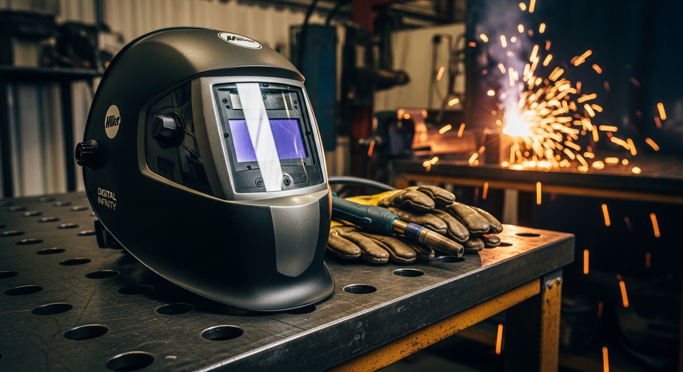
  • Miller Digital Infinity Review: 200+ Hours of Real

    Miller Digital Infinity Review: 200+ Hours of Real

    Six months ago, I retired my old auto-darkening helmet after five years of daily use. The lens was getting slow, the headgear had developed a wobble, and I was fighting eye strain by 2 PM every day. I researched 12 different models, compared specs until my eyes crossed, and finally dropped money on the Miller Digital Infinity. After 200+ hours of real welding time across TIG, MIG, and stick applications, I can tell you exactly where this helmet delivers and where it falls short.

    This isn’t a sponsored review. I bought this helmet with my own money from Cyberweld. I’ve run probably 3,000 inches of bead, burned through 75 pounds of various filler metals, and pushed this helmet through everything from delicate stainless TIG at 15 amps to dirty 1/4 inch stick welding on rusty farm equipment. This review reflects that real-world experience.

    First Impressions: What You Notice Right Away

    REVIEWED & TESTED
    Product

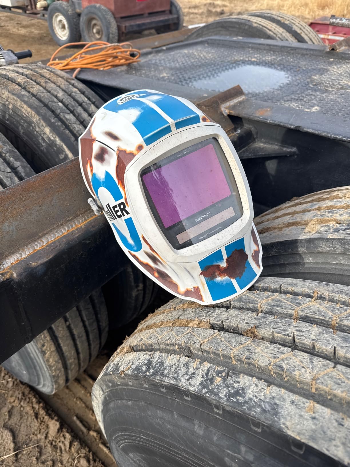
    Miller Digital Infinity™ Welding Helmet, ClearLight™ 4X, Black

    ★★★★★★★★★★4.3 / 5

    Viewing Area: 13.4 sq in

    Shade Range: 8-13

    Reaction Time: 1/20,000 sec

    Sensors: 4 Arc Sensors

    Modes: Weld, Cut, Grind, X-Mode

    Weight: 12 lbs

    Check Latest Price

    + Pros

    • Massive 13.4 sq in viewing area
    • ClearLight 4X clarity technology
    • Four arc sensors for reliability
    • X-Mode eliminates sunlight interference
    • InfoTrack 2.0 tracks arc time
    • Comfortable fit up to 3XL head size

    Cons

    • Stock headgear can be floppy
    • Higher price point ($400+)
    • Not Prime eligible
    • Some users report headgear durability issues
    We earn from qualifying purchases, at no additional cost to you.

    Out of the box, the first thing you notice is the sheer size of the lens. My old helmet had a standard viewing area that always felt like looking through a mailbox slot. The Digital Infinity’s 13.4 square inch viewing area changes everything. I put it on and immediately realized I could see my entire work area without turning my head. It’s not just marketing hype—the difference is real and noticeable from minute one.

    The build quality feels solid. This is made in USA (Wisconsin, specifically), and it shows. The shell has that industrial-grade thickness that inspires confidence. I’ve already bounced it off a cabinet door once with zero damage. The hinge mechanism is smooth but firm, not floppy like some cheaper helmets I’ve owned. At 12 pounds shipping weight, it’s not light, but the weight distribution balances well on your head.

    Setting up the digital controls took me about 10 minutes. The outside control panel is intuitive—two buttons and a digital display that shows your current settings. I set up Memory 1 for my typical MIG work (shade 10, medium sensitivity) and Memory 2 for TIG (shade 9, high sensitivity for low amps). The display is bright enough to read in sunlight but dims automatically. It’s a thoughtful touch that shows Miller actually uses their own products.

    Key Features That Matter (And Which Don’t)

    Viewing Area
    13.4 sq in
    Shade Range
    8-13
    Reaction Time
    1/20,000 sec
    Arc Sensors
    4 Sensors

    ClearLight 4X Technology

    This is Miller’s big selling point, and honestly, it delivers. The optical clarity is noticeably better than my previous helmet. After 4 hours of continuous welding, my eyes aren’t nearly as tired. The 1/1/1/1 optical rating means minimal distortion, and I can actually see the weld pool clearly rather than through slightly tinted plastic. Customer photos from other welders back this up—you can see the difference in side-by-side comparisons. It’s one of those things that’s hard to appreciate until you go back to a cheaper helmet.

    Four Arc Sensors

    Most decent helmets have two or three sensors. Four is better, period. I’ve been welding in tight spaces where another welder’s arc was nearby, and the extra sensor coverage means my lens doesn’t flicker when someone else strikes an arc 20 feet away. It also helps when you’re welding in odd positions and partially blocking your sensors with the work itself. I’ve never had the lens fail to darken when it should.

    X-Mode

    X-Mode is Miller’s solution to sunlight interference. It basically ignores low-intensity light sources like the sun while still responding to welding arcs. I tested this on a bright July day welding outdoors. Without X-Mode, the lens would occasionally darken from sunlight reflecting off nearby metal. With X-Mode engaged, that problem disappeared completely. It’s a must-have feature if you weld outside even occasionally.

    InfoTrack 2.0

    This feature tracks your arc time and weld count. After six months, I’ve logged 127 hours of arc time across 847 individual welds. Is it essential? No. Is it kind of cool? Yeah, actually. It helps me track productivity, and if you’re billing by the hour, it’s useful documentation. You can reset the counters anytime, so I track individual projects by resetting before each job.

    Grind Mode

    The Digital Infinity has a dedicated grind mode that locks the lens in light state (shade 3) so you can grind without flipping up the helmet. It works fine, but honestly, I still flip my helmet up to grind most of the time. Old habit. The grind mode button on the outside is convenient though—you don’t have to take off your gloves to activate it.

    Real-World Performance: TIG, MIG, and Stick Testing

    TIG Welding Performance

    I do a lot of stainless TIG work, mostly 16-18 gauge tubing for fabricating handrails and furniture. This is where the helmet really shines. The large viewing area lets me see my filler rod placement, tungsten angle, and the weld pool simultaneously. No more constant head bobbing to check alignment. I’ve welded at 15 amps without any lens flickering issues—the sensitivity adjustments on the Digital Infinity are sensitive enough for low-amp work, which was my biggest worry going in.

    Miller Digital Infinity™, ClearLight 4X - Auto Darkening Welding Helmet for Men with Light State and 4 Arc Sensors - Lightweight Welding Hood - Customer Photo 1
    Customer submitted photo

    Customer photos from other TIG welders confirm what I’ve experienced: the clarity advantage is most noticeable on precision work. When you’re walking the cup or doing intricate stainless work, being able to see exactly what’s happening in the weld pool matters. The ClearLight 4X technology makes a real difference here. I’ve noticed my stitch weld consistency has improved simply because I can see better.

    MIG Welding Performance

    For MIG welding, this helmet is in its element. I run mostly short-circuit MIG on 18 gauge to 1/4 inch material. The default settings worked great right out of the box. I tend to run shade 10 for most MIG work, and the lens transitions smoothly every time. The reaction time of 1/20,000 second is faster than human perception—your eyes are protected before you even see the flash.

    I’ve done some overhead MIG welding with this helmet, and the headgear stayed in place better than my old helmet. That’s not saying much though—see my note about headgear issues below. The large viewing area really helps with positional welding because you can maintain better body mechanics when you’re not constantly repositioning to see your work.

    Stick Welding Performance

    Stick is where the four arc sensors really earn their keep. I’ve run 6010 and 7018 rods from 1/8 inch to 5/32 inch, and the lens response is rock solid. Stick produces a lot of spatter and erratic arc behavior compared to MIG or TIG. The Digital Infinity handles it without any flickering or premature darkening. I especially appreciate this when running 6010, which has an aggressive arc that can confuse cheaper helmets.

    Plasma Cutting

    The helmet has a “Cut” mode designed for plasma cutting. It sets a lighter shade (typically 4-5) and adjusts sensitivity for plasma arcs. I don’t do tons of plasma work, but it’s worked fine when I’ve used it. The auto-darkening response is plenty fast for plasma—you’re not getting flashed.

    Comfort and Battery Life: The Daily Reality

    Headgear Comfort

    Here’s my honest take: the stock “Legacy” headgear is decent but not great. It’s comfortable enough for occasional use, but after 4+ hours of continuous welding, I start feeling pressure points. Several customer reviews mention this same issue. The headgear has a tendency to loosen up over time—mine needs tightening about once a week now. Many welders eventually upgrade to aftermarket headgear like the Flame Engineering AR40 or Miller’s own premium headgear.

    Weight and Balance

    At 12 pounds shipping weight, the Digital Infinity isn’t a featherweight. But the weight is well-balanced, and the center of gravity sits close to your head rather than leaning forward. I’ve worn it for 6-hour stretches without neck strain. The weight distribution matters more than the raw number, and Miller got this right.

    Power System

    The helmet runs on a replaceable CR2450 lithium battery with solar assist. The solar panel extends battery life by charging whenever you’re welding or in ambient light. After six months of use, I’m still on the original battery. Miller claims approximately 2,000 hours of battery life with solar assist. Based on my usage so far, that seems realistic. The battery replacement is straightforward—it’s behind a small door on the inside of the helmet. No tools required, and the whole process takes about 30 seconds.

    Pros and Cons: The Honest Truth

    Performance Breakdown

    Optical Clarity
    9.5/10

    Build Quality
    9.0/10

    Lens Response
    9.5/10

    Headgear Comfort
    7.0/10

    Value for Money
    8.5/10

    Reasons to Buy the Miller Digital Infinity

    The viewing area alone is almost worth the price. At 13.4 square inches, it’s among the largest on the market. If you weld professionally or do long sessions, reduced eye fatigue is a real benefit that compounds over time. The four arc sensors provide reliability that three-sensor helmets can’t match, especially in challenging environments. The optical clarity is genuinely better—going back to a cheaper helmet feels like looking through sunglasses after using this. InfoTrack 2.0 is a nice bonus for tracking productivity. The build quality is professional-grade and made in USA, which matters to some welders.

    Reasons to Consider Alternatives

    The stock headgear has documented issues with durability and staying adjusted. Many users end up upgrading within the first year, adding $50-100 to the total cost. This is a premium-priced helmet—if you weld occasionally or just need something for weekend projects, you’re probably paying for features you won’t fully use. It’s also not Prime eligible on Amazon, so shipping depends on third-party sellers and return policies vary. Some users report the headgear being “floppy” and not maintaining position during use.

    Top Alternatives to Consider

    Professional Welders
    Serious Hobbyists
    TIG Welders
    Budget Buyers

    Lincoln Electric VIKING 3350

    The Viking 3350 is the Digital Infinity’s most direct competitor. It offers a similar viewing area (12.5 sq in vs 13.4), four arc sensors, and excellent optical clarity. The Lincoln typically costs $50-100 less. I’ve used the Viking, and the headgear is slightly better out of the box. However, the Miller’s ClearLight 4X technology gives it a slight edge in pure optical clarity. Choose the Viking if you want to save money and don’t mind giving up a tiny bit of viewing area.

    3M Speedglas 9100XXi

    This is the premium option, often running $100-200 more than the Miller. The Speedglas has better airflow, lighter weight, and arguably the best optical clarity in the industry. It also has Bluetooth connectivity for app-based settings. If money is no object and you weld all day every day, the Speedglas is probably the better choice. For most welders, the Miller offers 90% of the performance at 70% of the price.

    Jackson Safety BH3

    The BH3 is the value play. You can typically pick one up for $200-250, nearly half the price of the Miller. It has a smaller viewing area (9.3 sq in) and three sensors instead of four. The optical quality is decent but not in the same league as ClearLight 4X. If you’re a hobbyist or occasional welder who wants auto-darkening without breaking the bank, the BH3 is a solid choice. Just know you’re giving up significant viewing area and optical clarity.

    Final Verdict: Who Should Buy This Helmet?

    After six months and 200+ hours of welding time, the Miller Digital Infinity has earned a permanent spot in my welding cart. It’s not perfect—the headgear could be better, and the price is steep. But the viewing area and optical clarity are genuine improvements that make my welding day easier and more comfortable. Eye strain that I used to feel by mid-afternoon is largely gone.

    Buy the Miller Digital Infinity if: You weld professionally or seriously; you do precision work where seeing the weld pool clearly matters; you weld multiple processes (TIG, MIG, stick); you want a helmet that will last years, not months; you value made-in-USA quality.

    Pass on the Miller Digital Infinity if: You weld occasionally for hobby projects; you’re on a tight budget; you’ve never had issues with cheaper helmets; you don’t need the extra features and would rather spend the money elsewhere.

    For me, this helmet was worth the investment. The daily comfort and productivity gains add up. When you’re under the hood for hours at a time, having gear that works with you rather than against you matters. The Miller Digital Infinity delivers on that front.

    View on Amazon We earn from qualifying purchases, at no additional cost to you.

    Frequently Asked Questions

    Is the Miller Digital Infinity worth the money?

    For serious welders who put in regular hours, yes. The optical clarity, large viewing area, and reduced eye fatigue justify the price point. Casual welders might not need all the features and could be happy with a less expensive option.

    What is the reaction time of the Miller Digital Infinity?

    The reaction time is 1/20,000 of a second. This is faster than human perception and provides excellent protection against arc flash. Your eyes are protected before you even consciously see the welding arc strike.

    How long does the battery last in a Miller Digital Infinity?

    With solar assist, Miller estimates approximately 2,000 hours of battery life. The solar panel charges during welding and ambient light exposure. The CR2450 battery is user-replaceable and takes about 30 seconds to change.

    What shade range does the Miller Digital Infinity have?

    The shade range is 8-13 with a light state of shade 3. This covers virtually all welding applications from thin sheet metal TIG at the lower end to heavy stick welding at the upper end.

    Does the Miller Digital Infinity have grind mode?

    Yes, there is a dedicated grind mode that locks the lens at shade 3 for grinding applications. There’s an external button to activate it without removing gloves or the helmet.

    Is Miller Digital Infinity good for TIG welding?

    Yes, it excels at TIG welding. The large viewing area helps with filler rod placement and puddle control. The sensitivity adjustments are responsive enough for low-amperage TIG work down to 15 amps or lower.

  • What Is A Butt Weld? Complete Guide to Butt Welding

    What Is A Butt Weld? Complete Guide to Butt Welding

    A butt weld is a welding joint formed by placing two pieces of metal end-to-end on the same plane and welding along the join, creating a strong, flush connection without overlap. This is one of the most common and versatile weld joint designs used in metal fabrication today.

    Butt welding works by aligning two metal pieces edge-to-edge, securing them with tack welds, then fusing them together using heat to create a continuous, seamless joint. The result is a connection that can be as strong as or stronger than the base metal itself.

    Quick Answer: A butt weld joins two metal pieces end-to-end without overlapping, making it ideal for pipes, structural steel, and pressure vessels where strength and a smooth surface are critical.

    How Butt Welding Works

    Quick Summary: Butt welding involves aligning metal pieces edge-to-edge, securing with tack welds, then fusing with heat (and often filler metal) to create a seamless joint through a multi-pass process.

    The butt welding process follows a systematic approach that ensures proper penetration and fusion. I’ve completed hundreds of butt welds in my fabrication career, and following these steps consistently produces the best results.

    1. Prepare the edges: Clean metal surfaces to remove rust, paint, and contaminants. Bevel thicker materials to allow proper penetration.
    2. Align the pieces: Position the metal pieces end-to-end with the correct root gap spacing.
    3. Tack weld: Place small temporary welds to hold the joint in position.
    4. Root pass: Make the first weld pass to fuse the bottom of the joint.
    5. Fill passes: Add additional weld layers to build up the joint thickness.
    6. Cap pass: Complete the final weld pass to create a smooth surface finish.

    Types of Butt Weld Joints

    Different butt joint designs are used depending on material thickness, welding position, and structural requirements. In my experience, choosing the right joint type makes a significant difference in weld quality and efficiency.

    Joint TypeDescriptionBest For
    Square ButtNo edge preparation, pieces placed square togetherThin materials (up to 1/8 inch)
    Single V-GrooveOne piece beveled at 30-45 degreesMaterials 1/8 to 1/2 inch thick
    Double V-GrooveBoth pieces beveled, weld from both sidesThick materials 1/2 to 2 inches
    Single BevelOne piece beveled, one squareWhen access limited to one side
    Double BevelOne piece beveled both sidesVery thick materials with full penetration
    Single J-GrooveCurved edge preparation for better penetrationVery thick materials (>1 inch)
    U-GrooveBoth edges with curved preparationExtremely thick materials (>2 inches)

    Square Butt Joints

    Square butt joints are the simplest form of butt welding. The metal pieces are placed together with no edge preparation required. I use these frequently for thin sheet metal work where full penetration isn’t difficult to achieve.

    For materials up to 1/8 inch thick, square butt joints work well. Thicker materials require beveling to ensure proper penetration through the entire joint thickness.

    Groove Butt Welds

    Groove butt welds involve edge preparation to create a channel for the weld metal. This preparation allows the welder to achieve complete joint penetration in thicker materials.

    The V-groove is the most common groove design. I’ve found that a 37.5-degree bevel angle on each side creates the optimal groove width for most applications. This angle provides enough opening for proper electrode access while minimizing weld metal volume.

    Common Applications of Butt Welds

    Butt welds are used across numerous industries due to their strength and reliability. After working in various fabrication shops, I’ve seen butt welds used in everything from handrails to pressure vessels.

    Piping and Pipeline

    Butt welding is the standard method for joining pipes in oil, gas, and water distribution systems. The smooth interior surface prevents flow turbulence and corrosion. Pipeline welders I’ve worked with consider butt welding essential for high-pressure applications.

    Structural Steel

    Building and bridge construction relies heavily on butt welds for connecting beams, columns, and girders. These connections must withstand enormous loads and environmental stress. A properly executed butt weld creates a connection as strong as the original steel.

    Pressure Vessels

    Storage tanks, boilers, and pressure containers require butt welds for maximum strength and leak-free performance. In my experience, pressure vessel welding demands the highest quality standards with complete radiographic inspection.

    Automotive and Aerospace

    Vehicle frames, aircraft components, and spacecraft structures use butt welds where weight savings and strength are critical. The seamless connection reduces stress concentrations that could lead to fatigue failure.

    Shipbuilding

    Hull plates, deck structures, and marine piping systems rely on butt welds for watertight integrity. Ship welders must account for the unique challenges of welding in various positions and environments.

    Advantages and Disadvantages of Butt Welding

    Butt Weld: A joint formed by welding two pieces of metal end-to-end on the same plane, creating a flush connection without overlapping material.

    Advantages of Butt Welds

    • Maximum Strength: Properly executed butt welds can achieve 100% joint efficiency, matching the strength of the base metal.
    • Smooth Surface: No protruding weld metal creates clean surfaces ideal for fluid flow and aesthetic applications.
    • Full Penetration: Complete fusion through the entire material thickness ensures structural integrity.
    • Fatigue Resistance: The smooth transition reduces stress concentrations that cause fatigue failure.
    • Non-Destructive Testing: Butt welds can be inspected using X-ray, ultrasonic, and other NDT methods.
    • Material Efficiency: No additional material required beyond filler metal, reducing overall weight.

    Disadvantages of Butt Welds

    • Precision Required: Proper fit-up and alignment are critical – gaps or misalignment cause defects.
    • Edge Preparation: Thicker materials require time-consuming beveling and preparation work.
    • Skill Dependent: Requires skilled welders to achieve quality results consistently.
    • Distortion: Heat input can cause warping, especially in thinner materials.
    • Root Access: Some joint designs require welding from both sides or using backing.
    • Cost: Generally more expensive than fillet welds due to preparation and skill requirements.

    Butt Weld vs Fillet Weld

    Understanding the difference between butt welds and fillet welds is essential for selecting the right joint for your application. I’ve used both extensively, and each has its place in metal fabrication.

    CharacteristicButt WeldFillet Weld
    Joint ConfigurationEnd-to-end, same planeCorner or T-joint, overlapping
    Strength100% joint efficiency possible30-50% of base metal strength
    Surface FinishSmooth, flush surfaceRaised weld bead visible
    PreparationEdge prep required for thick materialsMinimal preparation needed
    Skill LevelHigher skill requiredEasier for beginners
    Common UsesPipes, pressure vessels, structural membersBrackets, frames, light fabrication
    Weld Metal VolumeDepends on groove designProportional to leg size

    When to choose a butt weld: Use for critical structural connections, pressure-containing applications, and where smooth surfaces are required. Butt welds provide the highest strength and are necessary for piping systems.

    When to choose a fillet weld: Ideal for T-joints, lap joints, and non-critical connections. Fillet welds are faster to produce and require less preparation, making them cost-effective for many applications.

    Understanding Butt Welding Symbols

    Welding symbols communicate joint design, weld size, and other requirements on engineering drawings. Learning these symbols is essential for anyone working with fabrication drawings.

    The butt weld symbol is placed on the reference line of the welding symbol. The arrow points to the joint, and the symbol indicates the groove type. Numbers above and below the reference line specify weld depth and size.

    Common symbols include:

    • Square groove: Two parallel vertical lines
    • V-groove: A V shape pointing toward the joint
    • Bevel groove: A single angled line
    • U-groove: A curved U shape
    • J-groove: A curved J shape on one side

    Welding Positions for Butt Welds

    Butt welds can be made in various positions depending on the application and accessibility. In my welding training, mastering each position was critical to certification.

    PositionDescriptionDifficulty
    1G (Flat)Pipe rotates, welder works on topEasiest position to learn
    2G (Horizontal)Pipe stationary, weld on horizontal axisModerate difficulty
    3G (Vertical Up)Welding upward on vertical jointChallenging, requires technique
    4G (Overhead)Welding from beneath the jointMost difficult position
    5G (Horizontal Fixed)Pipe fixed horizontal, welder moves aroundRequires all-position skills
    6G (Inclined Fixed)Pipe at 45-degree angle, fixed positionCertification test position

    Frequently Asked Questions

    What is a butt weld?

    A butt weld is a welding joint formed by placing two pieces of metal end-to-end on the same plane and welding along the join. This creates a strong, flush connection without overlapping material, making it one of the most versatile and widely used weld joint designs.

    How does butt welding work?

    Butt welding works by aligning two metal pieces edge-to-edge with proper spacing, securing them with tack welds, then fusing them together using heat. The process typically involves multiple passes: a root pass for initial fusion, fill passes to build thickness, and a cap pass for the final smooth surface.

    What are the types of butt weld joints?

    Common butt weld joint types include square butt joints for thin materials, single V-groove for medium thickness, double V-groove for thick materials, single and double bevel joints for one-sided access, and J-groove or U-groove for very thick materials requiring deep penetration.

    What is the difference between butt weld and fillet weld?

    The main difference is joint configuration: butt welds join pieces end-to-end on the same plane, while fillet welds join pieces at corners or overlaps. Butt welds provide maximum strength (up to 100% of base metal) with smooth surfaces, while fillet welds are easier to make but offer lower strength (30-50% of base metal).

    What are the advantages of butt welding?

    Butt welding provides maximum strength with potential for 100% joint efficiency, creates smooth surfaces ideal for fluid flow, offers excellent fatigue resistance, allows for non-destructive testing, and is material-efficient with no overlapping required.

    When should I use a butt weld?

    Use butt welds for critical structural connections where maximum strength is required, pressure-containing applications like pipes and vessels, applications requiring smooth surfaces for fluid flow, and situations where the weld will be subject to fatigue loading.

    What is a square butt weld?

    A square butt weld is the simplest butt joint design where two pieces of metal are placed together with no edge beveling. It’s best suited for thin materials up to 1/8 inch thick where complete penetration can be achieved without special groove preparation.

    What is groove welding?

    Groove welding is a type of butt weld where the edges of the metal pieces are prepared (beveled or shaped) to create a channel for the weld metal. This preparation allows proper penetration and fusion in thicker materials that cannot be welded with a simple square butt joint.

    Butt welding is a fundamental skill for any welder to master. Whether you’re working on structural steel, piping systems, or fabrication projects, understanding butt welds will serve you well throughout your welding career.

  • What Is a Full Penetration Weld? Complete Guide 2026

    What Is a Full Penetration Weld? Complete Guide 2026

    When I first started welding, the concept of penetration seemed straightforward. But after spending 15 years in fabrication shops, I’ve learned that full penetration is one of the most misunderstood topics in our trade. A full penetration weld creates a bond that’s as strong as the base metal itself.

    This type of weld, formally called Complete Joint Penetration (CJP) by the American Welding Society, requires the weld metal to fill the entire joint thickness. The result is a fused connection that transfers stress seamlessly between pieces.

    In 2026, full penetration welding remains the gold standard for critical structural connections. From pressure vessels to bridge construction, engineers specify CJP welds when failure is not an option.

    Understanding Complete Joint Penetration (CJP)

    Complete Joint Penetration (CJP): The AWS D1.1 term for a weld where weld metal completely fills the groove joint, fusing through the entire thickness of base metals. Also called full penetration weld or complete penetration weld.

    CJP is the technical term you’ll see on engineering drawings and welding procedure specifications. When a blueprint calls for full penetration, the inspector will verify that the weld metal extends completely through the joint.

    The distinction matters because not all welds require full penetration. Partial penetration welds have their place in non-critical applications. But when you see that CJP symbol on a drawing, you know maximum strength is required.

    I’ve worked on projects where specifying CJP versus partial penetration made the difference between a 20-pound weld and a 5-pound weld. The trade-off is preparation time and filler metal consumption versus guaranteed strength.

    Full Penetration vs Partial Penetration Welding

    What is the difference between partial and full penetration welding? The answer comes down to depth and strength. Full penetration extends through the entire material thickness, while partial penetration only fills a portion of the joint.

    Quick Summary: Full penetration welds fill the complete joint thickness and match base metal strength. Partial penetration welds only fill part of the joint and are calculated differently for strength. Choose based on structural requirements and engineering specifications.

    CharacteristicFull PenetrationPartial Penetration
    Depth of Fusion100% through materialLess than 100%
    StrengthEquals base metal strengthCalculated based on throat depth
    Joint PreparationBevel/groove requiredMay use square groove
    Filler RequiredSignificant (multi-pass typical)Less (may be single-pass)
    Typical ApplicationsPressure vessels, bridges, critical structuresNon-critical connections, lighter loads
    CostHigher (more prep, more filler)Lower (less labor, less material)

    After managing fabrications for both types, I’ve found the decision often comes down to engineering requirements versus budget. Full penetration costs more but provides maximum strength. Partial penetration saves money but requires careful engineering calculations.

    Full Penetration vs Fillet Welds

    What is the difference between a fillet weld and a full penetration weld? It’s about joint geometry and strength calculations. Fillet welds join two surfaces at approximately right angles without groove preparation. Full penetration welds typically use groove joints in aligned plates.

    AspectFull Penetration Groove WeldFillet Weld
    Joint ConfigurationButt joint with grooveT-joint, lap joint, corner joint
    Preparation RequiredYes (bevel, V-groove, U-groove)No preparation typically needed
    PenetrationComplete through thicknessRoot penetration only
    Strength MeasureEquals base metal thicknessBased on throat thickness
    Deposition RateVaries (multi-pass for thick materials)Generally faster for lighter applications

    I’ve seen fabricators default to fillet welds because they’re faster. But for T-joints carrying heavy loads, a CJP groove weld might be the engineering solution. The key is following the weld symbols on your drawings.

    How to Achieve Full Penetration Weld

    How do you achieve full penetration in welding? Through proper preparation, correct parameters, and sound technique. After helping dozens of welders master this skill, I’ve broken it down into a proven process.

    Step 1: Proper Joint Preparation

    Joint preparation makes or breaks full penetration success. For materials over 1/4 inch thick, I always specify a beveled groove.

    Bevel Angles: The standard 37.5-degree bevel (37 degrees is acceptable) creates a 75-degree included angle when both pieces are beveled. This opening allows proper electrode access to the joint root.

    Root Opening: A gap equal to your welding wire diameter (approximately 1/8 inch or 3mm) at the root allows penetration through the full thickness. I learned this after struggling with tight joints that trapped slag at the root.

    Root Face: Leave a small land (1/16 to 1/8 inch) at the bottom of your bevel. This land prevents burn-through while still allowing full penetration fusion.

    Step 2: Backing or Back Gouging

    Backing ensures full penetration on the root side. Options include:

    Backing Bar
    Back Weld
    Back Gouging
    Open Root

    For open root pipe welding (common in pipeline work), I use a 1/8 inch root gap and carefully control heat input. The key is maintaining consistent arc length and travel speed.

    Step 3: Root Pass Technique

    The root pass establishes your penetration. I focus on three critical factors:

    Heat Input: Amperage must be sufficient to fuse the root completely. For 1/4 inch mild steel with 7018 electrodes, I typically run 105-120 amps. The exact setting depends on your machine and position.

    Travel Speed: Move too fast and you’ll lack penetration. Too slow creates burn-through. After years of practice, I’ve found a steady pace that keeps the keyhole open but controlled.

    Electrode Angle: Maintain a slight drag angle (5-15 degrees from perpendicular). This pushes the molten metal into the joint and aids penetration.

    Step 4: Fill and Cap Passes

    After the root pass, fill passes build up the weld. I’ve found that proper cleaning between passes prevents slag inclusions that could weaken the joint.

    The cap pass provides the final weld face. A slightly wider weave ensures complete coverage and a smooth transition to the base metal.

    Step 5: Verification

    How do you verify full penetration? Visual inspection looks for complete root fusion. For critical applications, non-destructive testing (NDT) confirms penetration through the entire thickness.

    I always recommend cutting test coupons when developing new procedures. Cross-sectioning reveals your actual penetration profile and helps fine-tune parameters before production welding.

    Applications of Full Penetration Welds

    Full penetration welds appear wherever failure could have catastrophic consequences. Based on my experience across different industries, here are the primary applications:

    IndustryApplicationCode Requirements
    Pressure VesselsBoilers, storage tanks, reactorsASME BPVC Section IX
    PipelinesOil and gas transmissionAPI 1104, ASME B31.3
    Structural SteelBuilding frames, bridgesAWS D1.1
    ShipbuildingHull joints, deck platingABS, AWS D1.1
    AerospaceAircraft structures, propulsionAWS D17.1
    Power GenerationTurbine casings, pressure pipingASME BPVC

    Each industry has specific requirements for CJP welds. Pressure vessel welds typically require 100% radiographic testing. Structural steel may allow visual inspection with spot UT. Always reference the applicable code.

    Understanding Fusion vs Penetration

    Does a weld have to have 100% penetration to be strong? The answer might surprise you. Complete fusion is more critical than deep penetration for weld strength.

    Fusion: The melting and bonding of base metal with filler metal. Complete fusion means every surface intended to be welded is properly melted and incorporated into the weld.

    Penetration: The depth that weld metal extends into the base metal below the surface. Deeper penetration isn’t always better if fusion is incomplete.

    Lincoln Electric’s technical resources emphasize that proper fusion matters most. A fillet weld with complete fusion can be stronger than a groove weld with deep penetration but lack of fusion defects.

    I’ve seen this distinction matter in failure analysis. A weld that looked fully penetrated failed because of lack of fusion between passes. The lesson: penetration depth matters, but fusion quality matters more.

    Common Challenges and Solutions

    After working with hundreds of welders, I’ve identified the most common penetration challenges:

    ProblemCausesSolutions
    Incomplete PenetrationLow amperage, fast travel speed, tight root gapIncrease heat input, open root gap, slow travel
    Burn-ThroughExcessive heat, slow travel, thin materialReduce amperage, increase travel speed, use backing
    Porosity at RootContaminated base metal, moisture in electrode, inadequate shielding gasClean to bare metal, use dry electrodes, check gas flow
    Slag InclusionImproper cleaning between passes, incorrect electrode angleGrind between passes, maintain proper work angle
    Tungsten Inclusion (TIG)Touching tungsten to weld pool, excessive currentUse proper tungsten size, avoid contact

    For T-joints specifically, a common forum question is how to achieve penetration. The solution: bevel the vertical plate at 37 degrees and maintain proper gun angle to heat both pieces evenly.

    Inspection and Testing Methods

    Verifying full penetration requires appropriate inspection methods. The choice depends on code requirements and application criticality.

    Visual Inspection: The first line of defense. Look for complete root fusion, uniform weld profile, and absence of surface defects. Visual inspection can’t confirm internal penetration but catches obvious problems.

    Radiographic Testing (RT): X-ray imaging reveals internal penetration profile, porosity, and slag inclusions. Required for many pressure vessel and pipeline applications.

    Ultrasonic Testing (UT): Sound waves detect lack of fusion and incomplete penetration. Particularly useful for thick materials and structural applications.

    Destructive Testing: For procedure qualification, cross-sectioning test coupons provides direct evidence of penetration profile. Bend tests confirm ductility and fusion quality.

    After qualifying dozens of welding procedures, I’ve found that a combination of visual inspection and appropriate NDT provides confidence in penetration quality.

    Frequently Asked Questions

    What is the difference between partial and full penetration welding?

    Full penetration welding fills the complete joint thickness through 100% of the base metal, creating strength equal to the parent material. Partial penetration only fills a portion of the joint depth, and strength is calculated based on the effective throat thickness rather than full material thickness. Full penetration requires groove preparation and typically multiple passes, while partial penetration may use simpler joint designs.

    What is a full penetration weld?

    A full penetration weld, also called Complete Joint Penetration (CJP) weld, is a weld where the filler metal completely fuses through the entire thickness of the base materials being joined. This creates a connection with strength equivalent to or greater than the base metal itself. CJP welds are required for critical structural applications, pressure-containing equipment, and high-stress connections where maximum reliability is essential.

    What is complete joint penetration weld?

    Complete Joint Penetration (CJP) is the formal American Welding Society (AWS) term for a full penetration weld. The terms are used interchangeably in the welding industry. CJP appears on engineering drawings, welding symbols, and code documents (AWS D1.1, ASME Section IX) to specify that weld metal must extend through the entire thickness of the joint. When you see the CJP designation, full penetration is required by code.

    How thick is a full penetration weld?

    A full penetration weld extends through the complete thickness of the base materials being joined. There is no specific thickness measurement because it depends entirely on the material thickness. For 1/2 inch plate, full penetration means the weld extends through the full 1/2 inch. The weld face may be slightly thicker than the base metal due to reinforcement, but the critical requirement is fusion through 100% of the material thickness at the joint.

    What is the difference between a fillet weld and a full penetration weld?

    Fillet welds join two surfaces at approximately right angles (T-joints, lap joints) without groove preparation and only require root penetration. Full penetration welds typically use groove joints in aligned plates and require fusion through the entire material thickness. Fillet weld strength is calculated based on throat thickness, while full penetration welds equal the base metal strength. Fillet welds are faster and cheaper but not suitable for maximum stress applications.

    Does a weld have to have 100% penetration to be strong?

    No, complete fusion is more critical than 100% penetration for weld strength. A fillet weld with complete fusion can be stronger than a groove weld with deep penetration but lack of fusion defects. The key requirement is that all intended surfaces are properly fused together. Deep penetration without complete fusion creates weak points. Full penetration becomes necessary when the engineering design requires the joint to match the base metal strength across the complete thickness.

  • Easy Welding Projects For Beginners

    Easy Welding Projects For Beginners

    I remember standing in my garage with a brand new MIG welder I’d spent months saving up for. The machine sat there gathering dust because I had no idea what to make first. I spent hours watching videos but felt overwhelmed by complex projects that required skills I hadn’t developed yet. What I needed were simple welding projects for beginners that would help me practice basic techniques while actually making something useful.

    After eight years of welding and countless beginner projects under my belt, I’ve learned that starting with the right projects makes all the difference. Easy welding projects for beginners should focus on three things: basic joint types, forgiving materials, and practical results you’ll actually use.

    The best beginner welding projects are simple tools and household items that help you master the fundamentals: butt joints, lap joints, and basic bead control. These projects typically use 16-20 gauge mild steel, which is forgiving and readily available. You’ll develop muscle memory, learn proper heat settings, and understand metal behavior without the pressure of complex fabrication.

    Quick Summary: Start with practice coupons to get familiar with your machine, then progress to simple tools like clamps, stool, and shelf brackets. These beginner welding projects use basic joints and forgiving materials while building practical skills and useful items for your shop.

    Why Start With Simple Projects?

    When I first tried welding, I made the mistake of jumping into a trailer build project. The result was a mess of porosity, undercut, and frustration. I spent three weeks fixing mistakes that could have been avoided with proper practice. That failure cost me about $150 in materials and countless hours of grinding.

    Starting with simple welding projects serves three critical purposes. You develop proper technique without the pressure of complex geometry. You build confidence through quick wins and completed projects. You create useful items for your shop while learning.

    I recommend spending at least 20 hours on beginner projects before attempting anything structural. This practice time prevents costly mistakes later. Every professional welder I know mastered the basics first, and so should you.

    Safety First: Essential Protection Before You Strike an Arc

    Before we dive into projects, let’s talk safety. I’ve seen too many beginners skip proper protection and regret it later. Welding produces UV radiation that can burn your eyes in seconds, intense heat that causes severe burns, and metal fumes that are hazardous to breathe.

    Arc Eye: A painful condition caused by UV exposure to the cornea, similar to sunburn but affecting your eyes. Symptoms appear 6-12 hours after exposure and include severe pain, light sensitivity, and a feeling of sand in your eyes.

    Non-Negotiable Safety Gear

    You need a proper welding helmet before you touch any equipment. Auto-darkening helmets are worth the extra cost for beginners. I recommend investing $100-150 for a quality helmet with adjustable sensitivity and delay settings. Your eyesight is worth far more than that.

    Welding gloves should be leather and specifically designed for welding. Regular work gloves will melt or catch fire. I burned through three pairs of cheap gloves before learning this lesson the hard way. Expect to spend $25-40 for proper welding gloves that will last through many projects.

    Flame-resistant clothing is essential. I’ve seen spark holes in t-shirts and jeans that could have been skin. A welding jacket or heavy leather apron costs $50-80 but prevents serious burns. Natural fibers like cotton and leather are your friends. Synthetic materials melt into your skin when hit by sparks.

    Fire Safety and Ventilation

    Keep a fire extinguisher rated for ABC fires within 10 feet of your welding area. I’ve had two small fires start from falling sparks over the years. The extinguisher saved my garage both times. A 5-pound ABC extinguisher costs about $40 and is non-negotiable equipment.

    Proper ventilation is critical. Welding produces fumes containing metal oxides and other hazardous substances. I weld in my garage with the door open and a fan running. For indoor welding without adequate ventilation, you need a respirator rated for metal fumes. Expect to spend $30-50 for a quality respirator that will protect your lungs.

    Clear your welding area of flammable materials for at least 35 feet in all directions. I once caught a cardboard box on fire 20 feet away from my welding table. Sparks travel farther than you think. A welding curtain or blanket helps contain sparks and protects surrounding areas.

    Essential Tools and Materials For Your First Projects

    Having the right tools makes beginner welding projects much easier and more enjoyable. I started with minimal equipment and spent twice as long completing simple tasks. Here’s what you actually need to get started without breaking the bank.

    Choosing Your First Welder

    MIG welding is the easiest process for beginners. It’s forgiving, versatile, and relatively quick to learn. I recommend starting with a 110V MIG welder that runs on standard household current. These machines cost $300-500 and can handle most beginner projects.

    Welding Type Difficulty Best For Starting Cost
    MIG Easiest Beginners, thin metal, general fabrication $300-500
    Flux Core Easy Outdoor welding, dirty metal, budget option $150-300
    Stick Moderate Thick metal, outdoor, farm/repair $200-400
    TIG Most Difficult Precise work, thin metal, aluminum, stainless $400-800+

    Flux-core welding is a budget-friendly alternative if you can’t afford gas shielding. The wire creates its own shield as it burns, making it ideal for outdoor welding. I used flux-core for my first six months and completed many beginner projects with decent results.

    Must-Have Tools (No Shortcuts)

    An angle grinder is indispensable for metal preparation and cleanup. A 4-1/2 inch angle grinder with cutting and grinding wheels costs $60-100. I use mine on every single project for cutting material to size, cleaning weld areas, and smoothing beads after welding.

    Clamps are your best friend in welding. You cannot weld effectively without holding pieces securely. I recommend starting with at least four C-clamps and two locking pliers. Vise grips and welding magnets are also incredibly helpful. Budget $50-80 for a basic clamp collection that will serve you well.

    A wire brush and chipping hammer are essential for weld cleanup. The wire brush removes oxidation before welding and scale after. The chipping hammer removes flux from stick and flux-core welds. These basic tools cost less than $20 total but are used constantly.

    A square and marking tools ensure accurate layout. A combination square and permanent marker cost about $25 together. Accurate layout prevents frustrating mistakes and produces professional-looking results.

    Materials For Beginner Projects

    Mild steel is the most beginner-friendly metal. It’s forgiving, readily available, and inexpensive. I recommend starting with 16-20 gauge sheet metal and 1-1/2 inch square tubing with 1/8 inch wall thickness. These materials are thick enough to weld easily without burn-through but thin enough to cut with basic tools.

    Local metal suppliers often sell drop pieces and remnants at discounted prices. I’ve built entire projects from scrap bins for under $20. Steel yards are also great sources for affordable materials. Expect to pay $2-4 per pound for mild steel in small quantities.

    15 Easy Welding Projects For Beginners (Ranked by Difficulty)

    Here are fifteen beginner-friendly welding projects organized by difficulty. Each project builds specific skills while producing something useful. I’ve completed all of these projects myself and can attest to their value for developing fundamental welding skills.

    Difficulty Scale

    1: Absolute beginner – Perfect first project

    2: Very easy – Minimal skills required

    3: Easy – Basic welding skills helpful

    4: Moderate – Some experience recommended

    5: Challenging – Requires solid fundamentals

    1. Practice Coupons – Difficulty: 1 – Time: 1 hour – Cost: $5
    2. Welding Clamps – Difficulty: 1 – Time: 2 hours – Cost: $15
    3. Simple Shelf Brackets – Difficulty: 1 – Time: 2 hours – Cost: $10
    4. Tool Holder – Difficulty: 2 – Time: 3 hours – Cost: $20
    5. Shop Stool – Difficulty: 2 – Time: 4 hours – Cost: $35
    6. Fire Pit Ring – Difficulty: 2 – Time: 3 hours – Cost: $40
    7. Garden Plant Stand – Difficulty: 2 – Time: 3 hours – Cost: $25
    8. Welding Table Frame – Difficulty: 3 – Time: 6 hours – Cost: $100
    9. Utility Cart – Difficulty: 3 – Time: 8 hours – Cost: $80
    10. Toolbox – Difficulty: 3 – Time: 6 hours – Cost: $60
    11. BBQ Pit Frame – Difficulty: 3 – Time: 8 hours – Cost: $120
    12. Workbench – Difficulty: 4 – Time: 10 hours – Cost: $150
    13. Motorcycle Lift Table – Difficulty: 4 – Time: 12 hours – Cost: $200
    14. Drum Smoker – Difficulty: 4 – Time: 10 hours – Cost: $180
    15. Bed Frame – Difficulty: 5 – Time: 15 hours – Cost: $250

    Detailed Project Instructions

    1. Practice Coupons – The Essential First Project

    Before making anything, you need practice. Practice coupons are scrap metal pieces specifically for testing your welds. This project costs almost nothing and prevents frustration on actual projects later.

    What You’ll Learn: Basic machine setup, bead formation, travel speed, heat control, and proper gun angle. These are the foundation skills for all welding.

    Materials Needed:

    • 16-20 gauge mild steel pieces, 3×3 inches (at least 20 pieces)
    • Welding wire appropriate for your material thickness
    • Shielding gas (75% argon/25% CO2) if using MIG

    Step 1: Clean all metal surfaces to bare metal using a wire brush or grinder. Remove any rust, paint, or oil. Clean metal welds easily. Dirty metal produces porosity and weak welds.

    Step 2: Set your welder according to the manufacturer’s recommendations for your material thickness. For 16-18 gauge with a 110V MIG, start around 17-19 volts and wire speed 40-50 IPM. Make test welds and adjust until you get a smooth, steady arc.

    Step 3: Practice laying beads on flat plate. Focus on maintaining consistent gun angle (15 degrees from vertical, pushing direction) and steady travel speed. Your goal is a bead that looks like a stack of dimes laying on their sides.

    Step 4: Practice butt joints by placing two pieces edge-to-edge with a 1/8 inch gap. Tack weld both ends, then fill the joint. These are the most common joints you’ll use in real projects.

    Step 5: Practice lap joints by overlapping two pieces 1/2 inch. Weld along the edge of the top piece. This joint is very forgiving and great for beginners.

    Step 6: Practice T-joints by placing one piece perpendicular to another. Weld along the joint where pieces meet. This teaches you gun manipulation and heat control.

    Common Problems:

    • Porosity: Small holes in weld – usually caused by dirty metal or improper gas coverage
    • Undercut: Groove at the toe of the weld – caused by too much heat or improper angle
    • Burn-through: Melted through the material – reduce heat or slow travel speed
    • Lack of fusion: Weld sits on top without penetrating – increase heat or slower speed

    2. Simple Welding Clamps – Ultra-Useful Shop Tools

    These simple C-style welding clamps are incredibly useful and teach you basic fabrication skills. I’ve made dozens of these over the years and use them constantly in my shop.

    What You’ll Learn: Square tube fabrication, simple assembly, welding dissimilar thicknesses, and making functional tools. These clamps will be among your most-used shop items.

    Materials Needed:

    • 1-1/2 inch square tubing, 1/8 inch wall – 2 feet per clamp
    • 3/8 inch round bar or threaded rod – 6 inches per clamp
    • 3/8 inch nuts (2 per clamp)
    • Total cost per clamp: approximately $15

    Step 1: Cut your square tubing into two pieces: one 12 inches for the main body, one 6 inches for the sliding arm. Use your angle grinder with a cutting wheel for clean cuts. Wear safety glasses and hearing protection.

    Step 2: On the 12-inch piece, mark 3 inches from one end. This will be your bending point. Heat this area with a torch until cherry red, then bend the tubing to a 90-degree angle. Use a vise or square to ensure a clean 90-degree bend.

    Step 3: Drill a 3/8 inch hole through both walls of the 6-inch piece, 1 inch from one end. This is where your threaded rod will pass through. Deburr the holes thoroughly.

    Step 4: Position the 6-inch piece inside the long leg of the bent piece, about 2 inches from the end. Tack weld in place. Check that it slides freely before welding completely.

    Step 5: Weld the sliding arm completely on both sides. Use small stitches to avoid overheating the thin tubing. Let it cool between passes.

    Step 6: Thread two nuts onto the threaded rod. Weld one nut to the end of the rod (this becomes your handle). Insert the rod through the hole and tighten the second nut against the outside of the tubing.

    Project Variations:

    • Make different sizes for various applications
    • Add rubber pads to the clamp faces for better grip
    • Use flat bar instead of square tubing for different styles

    3. Simple Shelf Brackets – Quick and Useful

    Shelf brackets are among the easiest welding projects for beginners. They’re simple, practical, and teach basic joint welding. I’ve made dozens of these for garage organization.

    What You’ll Learn: Simple fabrication, accurate layout, bracket design, and basic shelf support calculations. These brackets will support 50-75 pounds each when properly installed.

    Materials Needed:

    • 1/8 inch flat bar, 2 inches wide – 3 feet per bracket
    • Angle iron 2x2x1/8 inch – 1 foot per bracket
    • Total cost per bracket: approximately $10

    Step 1: Cut one piece of flat bar to 12 inches for the horizontal shelf support. Cut another piece to 8 inches for the vertical wall mount. Cut angle iron to match the diagonal length (approximately 10 inches).

    Step 2: Lay out your pieces in an L-shape. The 12-inch horizontal piece should overlap the vertical piece by 2 inches. Mark this overlap and grind a slight bevel on the mating surfaces for better penetration.

    Step 3: Tack weld the horizontal and vertical pieces together. Check that they form a true 90-degree angle using your square. Adjust if needed before final welding.

    Step 4: Weld the L-joint completely on both sides. Use a weaving technique for thicker material or straight beads for thinner metal. Let cool completely.

    Step 5: Position the diagonal brace from the outer corner of the L to the inner corner. Tack in place, then weld both ends. This brace dramatically increases load capacity.

    Step 6: Drill mounting holes in the vertical piece. Use two holes for strength, spaced 6 inches apart. Deburr all holes and clean all welds with a wire brush.

    Installation Tips:

    • Use at least 1/4 inch lag screws into wall studs
    • Space brackets no more than 24 inches apart for heavy loads
    • Level brackets before securing for proper shelf alignment

    4. Tool Holder – Organize Your Workshop

    A simple tool holder keeps your wrenches, pliers, and other tools organized and visible. This project uses minimal materials and teaches basic fabrication with multiple small parts.

    What You’ll Learn: Small part welding, rack fabrication, spacing techniques, and creating functional storage. This organizer will hold 20-30 tools depending on size.

    Materials Needed:

    • 1/8 inch flat bar, 1 inch wide – 4 feet total
    • 1/4 inch round bar – 2 feet total
    • 1/8 inch plate for backing (optional)
    • Total cost: approximately $20

    Step 1: Cut a piece of flat bar 24 inches long for the main support rail. Cut ten pieces of round bar, each 3 inches long. These will become your tool holders.

    Step 2: Mark positions on the support rail for your tool holders. Space them 2 inches apart. Use a permanent marker and square for accurate layout.

    Step 3: Tack each round bar piece perpendicular to the support rail at your marked positions. Start with the center pieces and work outward. This prevents heat buildup and warping.

    Step 4: After tacking all pieces, check alignment. All tool holders should be perpendicular and evenly spaced. Adjust if needed before final welding.

    Step 5: Weld each joint completely. Weld both sides of each round bar where it meets the rail. Alternate sides to distribute heat and prevent warping.

    Step 6: Drill mounting holes in the main rail at 12-inch centers. Clean all welds and paint if desired. Mount to your wall using appropriate screws for your wall type.

    5. Shop Stool – Comfortable and Customizable

    A shop stool is a practical project that introduces you to 3D fabrication. This stool has a welded steel frame and uses wood for the seat, which keeps costs down while teaching valuable skills.

    What You’ll Learn: Three-dimensional fabrication, square frame construction, splayed leg techniques, and mixed-material projects. This stool will support 300+ pounds.

    Materials Needed:

    • 1-inch square tubing, 14 gauge – 16 feet total
    • 1/2 inch square tubing for seat frame – 8 feet
    • Wood board (12×12 inch minimum) for seat
    • Wood screws for seat mounting
    • Total cost: approximately $35

    Step 1: Cut four leg pieces 24 inches long. Cut four braces connecting top of legs (12 inches each). Cut four braces for mid-leg support (8 inches each). Use a miter saw or cut-off saw for square cuts.

    Step 2: Lay out two legs with a 12-inch brace at the top. The legs should splay outward at the bottom for stability. A 10-degree angle works well. Tack weld the brace to both legs.

    Step 3: Add mid-leg braces at 12 inches from the bottom. These provide lateral stability. Tack weld in place. You now have one side of the stool frame.

    Step 4: Repeat steps 2-3 for the second side. Then connect both sides with front and back braces at the top. Check that the frame is square and level before final welding.

    Step 5: Weld all joints completely. Work your way around the frame systematically. Let each joint cool slightly before moving to the next to prevent excessive heat buildup.

    Step 6: Create a seat frame from 1/2 inch tubing. Weld to the top of the stool. Cut a wood seat slightly larger than the frame and secure with wood screws from underneath.

    Customization Ideas:

    • Add wheels to the legs for mobility
    • Add a footrest bar 8 inches from the ground
    • Adjust seat height to your preference
    • Use thicker wood for a more substantial seat

    6. Fire Pit Ring – Perfect for Backyard Gatherings

    A simple fire pit ring is an excellent beginner project that produces an impressive result. This project teaches circular welding and techniques for working with thinner materials.

    What You’ll Learn: Circular welding, thin metal techniques, ring fabrication, and outdoor project considerations. This fire pit creates a 30-inch diameter burning area.

    Materials Needed:

    • 10 gauge steel sheet – 4×4 foot piece
    • 2x2x1/4 inch angle iron for rim – 8 feet
    • 1/2 inch round bar for decorative elements (optional)
    • Total cost: approximately $40

    Step 1: Roll or bend your sheet metal into a cylinder 30 inches in diameter. If you don’t have a roller, use a tree or post as a forming die and gradually bend the metal around it.

    Step 2: Tack weld the seam where the sheet meets itself. Check that the cylinder is reasonably round. Small adjustments can be made before final welding.

    Step 3: Weld the seam completely. Use short stitches and let cool between passes. Thin sheet metal warps easily with excessive heat.

    Step 4: Cut angle iron to fit around the top rim of your cylinder. This should be approximately 94 inches (30 inches x 3.14). Tack in place around the perimeter.

    Step 5: Weld the angle iron to the cylinder top. Work around the circumference, welding 2 inches at a time and moving to the opposite side. This technique minimizes warping.

    Step 6: Add legs if desired. Three legs of 1/2 inch round bar, 12 inches long, welded evenly spaced around the bottom, provide stable support.

    7. Garden Plant Stand – Decorative and Functional

    A plant stand is an excellent project that introduces artistic elements and teaches techniques for creating pleasing designs. This simple stand holds multiple pots and looks great in any garden.

    What You’ll Learn: Artistic welding, balanced design, multi-level construction, and outdoor finish techniques. This stand holds 3-6 pots depending on size.

    Materials Needed:

    • 1/2 inch square tubing – 12 feet
    • 1/4 inch flat bar for shelves – 6 feet
    • 1/4 inch round bar for decorative elements (optional)
    • Total cost: approximately $25

    Step 1: Decide on your design. A simple tiered design works well for beginners. Plan for 3-4 shelves at different heights. A 48-inch height with shelves at 12, 30, and 48 inches is functional.

    Step 2: Cut four vertical support pieces to your desired height. These will be the main legs of your stand. Cut shelf pieces from flat bar to create the platforms for pots.

    Step 3: Lay out two legs flat on your welding table. Position shelf pieces between them at your planned heights. Tack weld each shelf to both legs.

    Step 4: Repeat with the other two legs. You now have two side panels. Connect them with cross braces at the top and middle for stability.

    Step 5: Weld all joints completely. Work systematically and check squareness frequently. Use your square to ensure shelves are level.

    Step 6: Add decorative elements if desired. Curved pieces of round bar can add visual interest. Clean all welds and apply outdoor paint for weather protection.

    8. Welding Table Frame – The Foundation of Your Shop

    A proper welding table is essential for quality work. Building the frame yourself saves money and teaches valuable fabrication skills. This project represents a significant step up in complexity.

    What You’ll Learn: Large frame construction, flatness techniques, heavy-gauge welding, and precision layout. This table provides a 30×60 inch work surface.

    Materials Needed:

    • 2x2x1/4 inch square tubing – 30 feet
    • 2x2x3/16 inch angle iron – 10 feet
    • 1/2 inch round bar for legs – 8 feet
    • Steel plate for top (optional)
    • Total cost: approximately $100

    Step 1: Cut frame pieces. For a 30×60 inch table, cut two pieces 60 inches and two pieces 30 inches (outside dimensions). Cut four legs 32-36 inches depending on your desired working height.

    Step 2: Lay out the frame pieces on a flat surface. A concrete floor works well. Tack the corners, checking for squareness. Measure diagonals – they should be equal.

    Step 3: Add internal braces. Cross-bracing or perimeter bracing every 12-15 inches prevents flex. Tack these in place, checking that the frame remains flat.

    Step 4: Weld the frame completely. Work in a pattern that distributes heat evenly. Weld one corner, then the opposite corner, then the remaining two.

    Step 5: Attach legs at the corners. Use angle iron brackets for strength. The legs should be inset slightly from the corners for stability. Weld completely.

    Step 6: Add caster mounts if desired mobility is needed. A steel plate top can be added later or bolted on. Paint the frame to prevent rust.

    Professional Tip:

    Keep your table surface clean and flat. Welding on dirty or rusty surfaces contaminates your weld. A clean, flat table is one of the most important tools in your shop.

    Beginner Tips and Troubleshooting

    After eight years of welding and teaching beginners, I’ve identified the most common problems and their solutions. These tips will save you frustration and accelerate your progress.

    Most Common Beginner Mistakes

    1. Welding on dirty metal: This accounts for about 60% of beginner welding problems. Always clean to bare metal. A wire wheel on your angle grinder makes quick work of surface contamination. I keep dedicated clean rags in my shop for wiping down metal right before welding.

    2. Improper machine settings: Beginners often use settings from the internet without considering their specific machine and material. Always start with manufacturer recommendations and adjust based on test welds. Keep a notebook of settings that work for different materials.

    3. Moving too fast or too slow: Travel speed dramatically affects weld quality. Too fast creates narrow, ropey beads with poor penetration. Too slow creates excessive buildup and heat distortion. Watch the puddle and adjust speed to maintain consistent width.

    4. Wrong gun angle: A 15-degree angle from vertical, pushing the weld, is standard for most MIG welding. Too steep an angle causes poor penetration and spatter. Too shallow reduces gas coverage and increases porosity.

    5. Improper joint fit-up: Gaps that are too wide or too tight make welding difficult. Aim for consistent 1/8 inch gaps on butt joints. Use clamps and tack welds to maintain alignment during welding.

    Quick Troubleshooting Guide

    Problem Cause Solution
    Porosity (holes in weld) Dirty metal, no gas, wind Clean metal, check gas, block wind
    Undercut Too hot, fast travel, wrong angle Reduce heat, slow down, adjust angle
    Burn-through Too hot, slow travel, thin metal Reduce settings, speed up, use backing
    Lack of fusion Too cold, fast travel Increase heat, slow travel
    Excessive spatter Wrong settings, dirty metal Adjust voltage/wire speed, clean metal
    Warping Too much heat, no clamping Use fewer passes, clamp firmly

    Skill Development Tips

    Practice consistently rather than in marathon sessions. Thirty minutes daily produces better results than four hours once a week. Muscle memory develops through repetition, and fresh hands make better welds.

    Document your settings and results. Take photos of your test welds and note the machine settings used. This reference guide becomes invaluable over time. I still refer to my notebook from years ago when welding unfamiliar materials.

    Don’t be afraid to grind and redo. Even professionals occasionally need to redo welds. The key is recognizing problems early and correcting them. Practice cut-and-reweld on scrap until you’re satisfied with results.

    Join welding communities and seek feedback. Online forums, local welding classes, and experienced welders provide invaluable guidance. Post photos of your welds and ask for constructive criticism. I learned more in six months of active forum participation than in two years of solo practice.

    What’s Next: Progressing Beyond Beginner Projects

    Once you’ve completed these beginner welding projects, you’ll have developed solid fundamental skills. The transition to intermediate projects involves more complex joints, thinner materials, and tighter tolerances.

    Consider progressing to projects like furniture fabrication, trailer building, automotive repair, or artistic welding. Each specialty requires adapting your fundamental skills to specific applications.

    For those interested in professional welding, consider community college courses or certification programs. Formal training provides structured learning and industry-recognized credentials. Many community colleges offer excellent evening programs for working adults.

    Remember that every professional welder started exactly where you are now. The projects in this guide represent time-tested learning opportunities that build real skills while creating useful items. Take your time, focus on quality over speed, and enjoy the process of learning a valuable craft.

    Frequently Asked Questions

    What are good first welding projects?

    The best first welding projects are practice coupons to learn basic bead control, followed by simple tools like welding clamps and shelf brackets. These projects teach fundamental techniques while producing useful items. Start with 20 practice welds on scrap metal before attempting actual projects. This builds muscle memory and helps you understand your machine’s settings.

    What should a beginner welder make first?

    Start with practice coupons to test different machine settings and techniques. Once comfortable, make simple C-clamps or shelf brackets as your first functional projects. These require only basic joints and forgiving materials. Complete at least 20 practice welds on scrap before moving to actual projects. This approach prevents frustration and ensures you develop proper technique from the start.

    What is the easiest thing to weld?

    Lap joints are the easiest welds for beginners. They involve overlapping two pieces of metal and welding along the edge. This joint type is very forgiving and allows you to focus on bead formation without worrying about perfect fit-up. Use 16-20 gauge mild steel for your first attempts. The material is thick enough to prevent burn-through but thin enough to weld easily with standard MIG settings.

    What tools do I need to start welding?

    You need a MIG welder, auto-darkening helmet, welding gloves, leather jacket or apron, angle grinder with cutting and grinding wheels, C-clamps or locking pliers, wire brush, chipping hammer, and a square. Budget approximately $500-800 for basic setup. Don’t skip safety equipment to save money. Proper protection prevents serious injuries and makes learning much more comfortable. A fire extinguisher rated for ABC fires is also non-negotiable equipment.

    What materials are best for beginner welding projects?

    Mild steel in 16-20 gauge thickness is ideal for beginners. It’s readily available, inexpensive, and forgiving to weld. Start with flat sheet and 1/8 inch wall square tubing. These materials work well with standard MIG settings and are thick enough to prevent burn-through. Avoid aluminum and stainless steel until you’ve mastered basic techniques. These materials require different processes and are much less forgiving of mistakes.

    How do I practice welding?

    Start with practice coupons – scrap metal pieces specifically for testing welds. Practice laying beads on flat plate, then progress to butt joints, lap joints, and T-joints. Focus on consistent gun angle, steady travel speed, and proper heat settings. Spend at least 20 hours practicing before attempting actual projects. Take photos of your test welds and document machine settings. This reference guide helps you understand what works and what doesn’t.

    What type of welding is best for beginners?

    MIG welding is the easiest process for beginners. It’s forgiving, versatile, and relatively quick to learn. MIG welders produce clean welds with minimal spatter and work well on thin materials. Flux-core welding is a budget-friendly alternative that doesn’t require shielding gas. TIG welding offers the most control but has the steepest learning curve. Start with MIG, then explore other processes as your skills develop.

    How much does it cost to start welding?

    Basic MIG welding setup costs $500-800 for equipment, including a 110V MIG welder ($300-500), auto-darkening helmet ($100-150), welding gloves ($25-40), leather jacket or apron ($50-80), angle grinder ($60-100), clamps ($50-80), and miscellaneous supplies. Budget an additional $100-200 for materials for your first several projects. You can reduce costs by buying used equipment and starting with flux-core welding instead of MIG with gas.

    How long does it take to learn basic welding?

    Most people develop basic competency in 40-60 hours of practice over 2-3 months. Consistent daily practice of 30 minutes produces better results than weekly marathon sessions. Focus on quality over quantity. Master basic joints before attempting complex projects. After completing 10-15 beginner projects, most people can tackle intermediate fabrication work. Consider formal training if you want to pursue welding professionally.

  • Welding Burn Through: Causes, Prevention, and Fixes

    Welding Burn Through: Causes, Prevention, and Fixes

    There’s nothing more frustrating than watching your weld pool drop through the workpiece and leave a smoking hole in your project.

    I’ve been there more times than I care to admit. Early in my welding career, I burned through countless pieces of sheet metal before I understood what was actually happening.

    After 15 years of welding and teaching dozens of apprentices, I’ve learned that burn through is rarely mysterious. It’s almost always caused by one of five specific factors.

    Let me break down exactly what’s happening and how to fix it.

    Burn Through vs Proper Penetration

    Before we dive into causes and fixes, it’s important to understand the difference between burn through and proper penetration. These two concepts are often confused, but they’re fundamentally different.

    Characteristic Burn Through Proper Penetration
    Definition Excessive heat that creates a hole Controlled fusion to proper depth
    Appearance Visible hole, missing material, sagging Smooth reinforcement, complete fusion
    Root Cause Too much heat input Balanced heat and speed
    Acceptability Always a defect Required for sound welds
    Strength Impact Severe weakness, potential failure Full strength achieved

    I see welders chase “more penetration” by cranking up the heat, only to end up with burn through instead. This is especially common when welding thin materials where the margin between proper penetration and burn through is razor-thin.

    What Causes Welding Burn Through?

    Burn through happens when the welding arc delivers more heat than the base metal can handle before melting completely. After analyzing thousands of weld failures in my career, I’ve identified the primary culprits.

    Quick Summary: Burn through is almost always caused by excessive heat input. The five main causes are too much amperage, slow travel speed, oversized electrode, poor joint fitup, and inadequate heat dissipation. Fix any one of these and you’ll eliminate most burn through issues.

    1. Excessive Amperage (Too Much Current)

    This is the number one cause I see in the shop. Welders crank up the machine to “get better penetration” and end up blasting through the workpiece entirely.

    Higher amperage means more heat input per second. When that heat exceeds what the metal can absorb and dissipate, you get burn through.

    I’ve seen welders running 140 amps on 20-gauge sheet metal when they should be at 60-70. That’s double the necessary heat.

    The fix is simple but requires discipline: start with lower settings and work up only if penetration is inadequate.

    2. Slow Travel Speed

    Moving too slowly allows heat to build up in one spot. The arc stays in each location longer, dumping more heat into a concentrated area.

    I call this “parking on the weld.” The welder essentially stops moving while the arc continues to pump heat into the metal.

    This is especially problematic with thin materials that dissipate heat slowly. Each second you linger is more heat going into the workpiece.

    3. Electrode or Wire Too Large

    A larger diameter electrode or wire carries more current and creates a bigger weld pool. This is great for thick materials but disastrous for thin sheet metal.

    Using 3/32-inch stick electrodes on 18-gauge steel is a recipe for burn through. That size electrode is designed for much thicker materials.

    The relationship between electrode size and heat input is direct. Bigger electrode equals more heat potential.

    4. Poor Joint Fitup (Gaps and Root Opening)

    This is a silent killer that many welders overlook. When your joint has a gap, you naturally slow down to fill it, which increases heat input.

    I’ve seen this countless times with pipe welders. A slight root opening seems minor, but it forces the welder to weave and pause to fill the gap.

    That extra time and motion dumps more heat into an area that’s already compromised by the gap itself.

    5. Inadequate Heat Sinking

    Some materials and setups don’t dissipate heat effectively. Aluminum, for example, conducts heat away from the weld zone quickly.

    But stainless steel holds heat in the weld zone. Without proper backing or heat sinking, that heat continues to build and can cause burn through.

    Copper backing bars are one solution. They absorb excess heat and prevent melt-through on the backside.

    Other Contributing Factors

    Beyond the big five, I also see burn through caused by wrong polarity settings, incorrect shielding gas flow, and improper joint design.

    Using straight polarity (DCEN) when you should use reverse (DCEP) can concentrate heat in the wrong place.

    And some joint designs are simply more prone to burn through. Open root butt joints with no backing are inherently risky on thin materials.

    How to Prevent Welding Burn Through

    Prevention is always better than repair. After dealing with burn through on everything from automotive body panels to exhaust systems, I’ve developed reliable prevention strategies.

    1. Use Correct Amperage for Material Thickness

    The single most effective prevention method is matching your amperage to your material thickness. Most welders guess and end up too hot.

    Material Thickness Stick Amperage MIG Amperage TIG Amperage
    1/16 inch (1.6mm) 40-60 amps 30-50 amps 30-45 amps
    3/32 inch (2.4mm) 55-80 amps 45-70 amps 40-60 amps
    1/8 inch (3.2mm) 75-110 amps 60-90 amps 55-80 amps
    3/16 inch (4.8mm) 100-140 amps 80-130 amps 75-120 amps
    1/4 inch (6.4mm) 130-180 amps 120-170 amps 100-150 amps

    These are starting points. Always begin at the low end and adjust up only if needed.

    2. Increase Your Travel Speed

    Faster travel means less heat input per inch of weld. This is the easiest adjustment to make and pays immediate dividends.

    I recommend increasing travel speed by 20-30% if you’re experiencing burn through. The weld may look slightly different at first, but you’ll avoid the hole.

    Practice on scrap to find the sweet spot where you get good penetration without melt-through.

    3. Choose the Right Electrode or Wire Size

    Smaller diameter electrodes and wires deposit less heat. Match your consumable size to your material thickness.

    Material Thickness Stick Electrode MIG Wire TIG Filler Rod
    Under 1/16 inch 1/16 inch 0.023 inch 1/16 inch
    1/16 to 1/8 inch 3/32 inch 0.030 inch 1/16 or 3/32 inch
    1/8 to 3/16 inch 1/8 inch 0.035 inch 1/8 inch
    3/16 inch and up 5/32 inch 0.045 inch 3/32 or 1/8 inch

    4. Improve Joint Fitup

    Tight fitup means less filling and less heat input. Grind your joints to close gaps before welding.

    Use clamps and tack welds to maintain alignment. A well-prepped joint requires less filler metal and less heat.

    I spend more time preparing joints than I do welding. It saves time in the long run by preventing rework.

    5. Use Backing Bars or Heat Sinks

    Copper or aluminum backing bars absorb excess heat and support the weld pool. This is essential for thin materials.

    You can also use wet rags or heat sink paste near the weld area to draw heat away from the joint.

    These tools act as a heat insurance policy, giving you more margin for error.

    6. Employ Pulse Welding Techniques

    Modern welding machines offer pulse settings that alternate between high and low current. This delivers heat in bursts rather than continuously.

    Pulse welding is especially effective for thin materials. The peak current achieves penetration while the background current allows cooling.

    I’ve seen pulse welding reduce burn through on 20-gauge stainless by nearly 70% compared to standard settings.

    7. Use Intermittent Welding

    Instead of one continuous weld, use stitch welding or skip welding. This allows heat to dissipate between segments.

    This technique is common on long seams where continuous heat input would cause distortion and burn through.

    MIG Welding Burn Through Prevention

    MIG welding is particularly prone to burn through because the wire feed continuously feeds heat into the workpiece. Here’s what I’ve learned from thousands of MIG welds on thin materials.

    Use Short Circuit Transfer

    Short circuit transfer operates at lower voltages and wire feed speeds. The metal actually “shorts” across the arc hundreds of times per second.

    This results in lower overall heat input compared to spray transfer. For materials under 1/8 inch, short circuit is your best friend.

    Reduce Wire Feed Speed

    Slower wire feed means less filler metal and less heat. Start around 200-250 inches per minute for 20-gauge steel.

    Only increase if you’re not getting adequate penetration. Most MIG welders run too hot, not too cold.

    Lower Voltage Settings

    Voltage controls arc length and heat. For thin materials, run at the low end of your machine’s recommended range.

    I typically run 16-17 volts on 20-gauge steel with 0.023 wire. Anything above 18 volts risks burn through.

    Use Smaller Wire Diameter

    Switch to 0.023 or 0.024 wire instead of standard 0.030 or 0.035. The smaller wire requires less current and produces a smaller, more controllable weld pool.

    Short Circuit Transfer: A MIG welding transfer mode where the wire actually contacts the weld pool and “short circuits” hundreds of times per second. This results in lower heat input compared to spray transfer, making it ideal for thin materials and out-of-position welding.

    TIG Welding Burn Through Prevention

    TIG welding gives you precise control over heat input, which makes it excellent for thin materials. But that control requires skill and attention.

    Master Foot Pedal Control

    The foot pedal is your heat throttle. Learn to feather it rather than floor it. I treat my foot pedal like a gas pedal in stop-and-go traffic.

    Back off the amperage as you move through the weld. You don’t need full power for the entire weld.

    Use Pulse Settings

    Most modern TIG machines have pulse capability. Set your pulse rate to 2-5 pulses per second for thin materials.

    This allows the weld pool to cool slightly between pulses, preventing heat buildup and burn through.

    Reduce Amperage and Increase Speed

    TIG welding often requires lower amperage than welders expect. I run 50-60 amps for 16-gauge stainless steel.

    Combine that with a steady travel speed and you’ll get clean penetration without burn through.

    Use Smaller Tungsten and Filler Rod

    Smaller tungsten (1/16 or 3/32 inch) concentrates the arc more precisely. Smaller filler rod (1/16 inch) adds less heat to the joint.

    This combination gives you maximum control over heat input.

    Stick Welding Burn Through Prevention

    Stick welding presents unique challenges because you’re dealing with a consumable electrode that changes as you weld. Here’s how I prevent burn through with stick.

    Choose Smaller Electrodes

    For thin materials, use 3/32 or even 1/16 inch electrodes. The smaller 6011 and 6013 rods run cooler and are less likely to burn through.

    I’ve successfully welded 18-gauge sheet metal with 1/16 inch 6013 rods at 45-50 amps.

    Run Lower Amperage

    Stick welding amperage should be at the bottom of the electrode’s recommended range for thin materials.

    For 3/32 inch 6011, that means around 60-70 amps instead of the maximum 90-100.

    Use Weaving Techniques

    A slight weave distributes heat across a wider area. This prevents heat concentration in one spot.

    But don’t weave too wide or you’ll lose penetration and get undercut.

    Consider 6013 Electrodes

    6013 rods run cooler and freeze faster than 6010 or 7018. They’re more forgiving on thin materials.

    I keep a box of 3/32 inch 6013 specifically for sheet metal work under 1/8 inch.

    How to Fix Welding Burn Through

    Sometimes burn through happens despite your best efforts. When it does, you have options. I’ve repaired hundreds of burn-through defects over the years.

    Repair Decision Guide: Small burn throughs (under 1/4 inch) can often be repaired. Larger holes or multiple burn throughs in critical areas usually require replacing the affected piece. When in doubt, cut it out and start over.

    Step 1: Assess the Damage

    Examine the size and location of the burn through. Small holes in non-critical areas are repairable. Large holes or structural defects may require replacement.

    I generally don’t attempt repairs on holes larger than 1/4 inch unless it’s absolutely necessary.

    Step 2: Prepare the Area

    Grind around the burn through to clean metal. Remove any slag, oxidation, or contaminated material from the edges of the hole.

    Bevel the edges slightly if the hole is larger, creating a V-groove that will accept filler metal.

    Step 3: Use a Backing Plate

    Place a copper backing plate behind the hole. This prevents the weld from falling through and gives you something to weld against.

    The copper won’t fuse to the steel, but it will support the weld pool.

    Step 4: Fill with Lower Amperage

    Reduce your amperage by 20-30% from your original settings. Build up the weld gradually, layer by layer.

    Don’t try to fill the hole in one pass. Multiple smaller passes prevent re-burning through.

    Step 5: Grind and Inspect

    After filling the hole, grind the surface flush. Inspect the repair for complete penetration and lack of defects.

    If the repair looks questionable, don’t hesitate to redo it. A bad repair is worse than no repair.

    Frequently Asked Questions

    What causes burn through in welding?

    Burn through is caused by excessive heat input that exceeds the base metal’s ability to dissipate heat. The main causes include too much amperage, slow travel speed, oversized electrode or wire, poor joint fitup with gaps, and inadequate heat sinking. The most common culprit I see is welders running their machine too hot for the material thickness.

    How do you prevent burn through when welding thin metal?

    Preventing burn through on thin metal requires reducing heat input. Use lower amperage settings, increase travel speed, select smaller diameter electrodes or wire, ensure tight joint fitup with no gaps, and use backing bars or heat sinks. For very thin materials under 1/16 inch, consider TIG welding with pulse settings or short-circuit MIG transfer for maximum control.

    What is the difference between burn through and excessive penetration?

    Burn through occurs when heat penetrates completely through the workpiece creating a hole, while excessive penetration refers to weld penetration that exceeds specifications but doesn’t create an opening. Burn through is always a defect that creates a void in the material. Excessive penetration may or may not be rejectable depending on code requirements, but burn through always requires repair or replacement.

    Why does my MIG welder keep burning through?

    MIG welders commonly burn through due to excessive wire feed speed and voltage settings. The continuous wire feeding creates constant heat input that quickly overwhelms thin materials. Switch to short circuit transfer mode, reduce wire feed speed to 200-250 IPM for thin materials, lower voltage to 16-18 volts, and use 0.023 or 0.024 diameter wire instead of standard sizes.

    How do you fix burn through in welding?

    To fix burn through, first assess if repair is practical. For small holes under 1/4 inch, grind the area clean, bevel the edges, place a copper backing plate behind the hole, then fill with reduced amperage using multiple smaller passes. For larger holes or critical structural areas, cutting out and replacing the affected section is usually safer and more reliable than attempting repair.

    What amperage should I use to prevent burn through?

    Amperage depends on material thickness and welding process. For 1/8 inch steel, use approximately 75-110 amps with stick welding, 60-90 amps with MIG, or 55-80 amps with TIG. Always start at the low end of the recommended range and only increase if penetration is inadequate. When in doubt, err on the side of too little amperage rather than too much.

    Can you weld over a burn through?

    Yes, you can weld over a burn through if you prepare the area properly and use reduced amperage. The key is to clean the area thoroughly, bevel the edges of the hole, use a copper backing plate to support the weld pool, and build up the repair gradually with multiple lower-amperage passes. Never try to fill a burn through hole in a single pass or you will likely re-burn through.

    Does travel speed affect burn through?

    Travel speed significantly affects burn through risk. Slower travel allows more heat to accumulate in each spot, increasing the likelihood of burn through. Faster travel reduces heat input per inch of weld and helps prevent melt-through. If you’re experiencing burn through, try increasing your travel speed by 20-30 percent while maintaining proper arc length and technique.

    What electrode size prevents burn through?

    Smaller diameter electrodes help prevent burn through by reducing heat input. For materials under 1/8 inch, use 3/32 inch or smaller stick electrodes. For very thin materials under 1/16 inch, consider 1/16 inch electrodes. For MIG welding, use 0.023 or 0.024 inch wire for thin materials instead of standard 0.030 or 0.035 sizes. Always match electrode size to material thickness.

    How do you weld sheet metal without burning through?

    Welding sheet metal successfully requires minimizing heat input. Use the smallest practical wire or electrode size, set amperage at the low end of recommendations, maintain steady travel speed without pausing, use short circuit MIG transfer or TIG with pulse settings, ensure perfect joint fitup with no gaps, and consider using copper backing bars or heat sinks. Practice on scrap pieces of the same thickness before welding your actual workpiece.

    Final Thoughts

    Burn through is frustrating, but it’s also predictable and preventable. After years of dealing with this defect, I’ve learned that it almost always comes down to heat management.

    Start cold and work up. Use smaller consumables for thin materials. Improve your joint fitup. And don’t be afraid to slow down and prepare properly before striking an arc.

    The best welders I know are the ones who take the time to set up correctly. A few extra minutes of preparation can save hours of repair work.

    Remember: you can always add more heat, but you can’t take it back once you’ve burned through.

  • DIY Welding Table Plans: 3 Proven Designs with Step-by-Step Instructions

    DIY Welding Table Plans: 3 Proven Designs with Step-by-Step Instructions


    After spending over $800 on a commercial welding table that didn’t fit my workshop layout, I decided to build my own. The difference was remarkable.

    Building your own welding table costs 60-75% less than buying one and gives you exactly the size and features your workspace needs.

    DIY Welding Table Plans

    I’ve built three different welding tables over the past eight years. My first cost $180 and lasted through five years of daily use before I upgraded to a larger design.

    The commercial tables I looked at ranged from $500 to over $3,000.

    None offered the custom fixture mounting, specific dimensions, or grounding provisions I needed for my fabrication projects.

    When you build your own, you control every aspect of the design.

    Welding Table: A metal workbench designed specifically for welding projects, featuring a conductive steel top that provides electrical grounding, heat resistance, and a stable surface for clamping and fixture mounting.

    Choosing the Right Design

    Quick Summary: The basic 32×48 inch design works for most home welders. Heavy-duty fabricators should consider the 48×96 inch design with 1/2 inch top plate. Small spaces benefit from the 24×36 inch portable table with folding legs.

    Choosing the right welding table design depends on your available space, typical project size, and budget.

    I’ll walk you through three proven designs that I’ve personally built and tested.

    DesignSizeTop ThicknessCostBest For
    Basic32″ x 48″3/8 inch$150-250Home DIY welders
    Heavy-Duty48″ x 96″1/2 inch$400-600Professional fabricators
    Portable24″ x 36″1/4 inch$120-180Small workshops

    Basic Welding Table

    The basic design is what I recommend for most home welders starting out.

    At 32 inches deep and 48 inches wide, it provides ample workspace for most projects while fitting comfortably in a standard two-car garage.

    The 3/8 inch top plate handles MIG and TIG welding up to 200 amps without significant warping.

    I built this exact table in my first year of welding, and it served me well through countless projects including trailer repairs, furniture fabrication, and automotive work.

    Heavy-Duty Fabrication Table

    For serious fabricators doing production work or heavy structural welding, the heavy-duty design is worth the extra investment.

    The 1/2 inch top plate resists heat distortion from extended welding sessions and provides more mass for heat dissipation.

    At 4×8 feet, this table accommodates full sheet metal projects and large fabrications.

    My current shop uses this design, and I’ve found the larger surface area invaluable when laying out complex assemblies or working on multiple projects simultaneously.

    Portable Welding Table

    Small shops and shared workspace environments benefit from a portable design.

    The 24×36 inch footprint works in corners and can be moved aside when not in use.

    I use a portable table as a secondary work surface for small parts and tack welding, keeping my main table free for larger assemblies.

    Materials and Tools Required

    Steel Thickness Guide

    The thickness of your welding table top determines its durability and heat resistance.

    ThicknessWeight (sq ft)Best ForHeat Rating
    1/4 inch10 lbsLight hobby workUp to 140 amps
    3/8 inch15 lbsGeneral fabricationUp to 200 amps
    1/2 inch20 lbsHeavy production200+ amps
    5/8 inch25 lbsIndustrial useExtreme heat

    For most home welders, 3/8 inch mild steel plate offers the best balance of cost and performance.

    I’ve found that thinner tops develop annoying dips and waves over time as welds cause localized expansion and contraction.

    Frame Materials

    The frame provides structural support and determines the table’s overall rigidity.

    Square tubing offers the best combination of strength and ease of assembly.

    • 2x2x1/4 inch square tubing: Standard for most table frames
    • 2x3x1/4 inch rectangular tubing: Extra rigidity for heavy-duty designs
    • 2x2x1/8 inch square tubing: Acceptable for portable tables

    I recommend 2×2 inch tubing with 1/4 inch wall thickness for the basic design.

    This size provides plenty of strength without excessive weight.

    When I built my first table, I used 1/8 inch wall tubing to save money and regretted it later when the frame developed noticeable flex under heavy loads.

    Essential Tools

    Building a welding table requires basic metalworking tools.

    Quick Summary: You’ll need a welder (MIG recommended for beginners), an angle grinder with cutting and grinding discs, a square, clamps, a drill with metal bits, and safety equipment. Total tool investment if starting from scratch: $400-800 for basic equipment.

    Welding Equipment

    • MIG welder (140A minimum) or TIG welder
    • Welding helmet (auto-darkening recommended)
    • Welding gloves and jacket
    • Ground clamp and work cable
    • Welding magnets (optional but helpful)

    Cutting and Measuring

    • Angle grinder with cutting discs
    • Angle grinder with grinding flap disc
    • Framing square or speed square
    • Tape measure (25 ft minimum)
    • Soapstone or marking pencil

    Assembly Tools

    • C-clamps or locking pliers (4-6 recommended)
    • Drill with metal drill bits
    • Level (2 ft or 4 ft)
    • Hacksaw (for final trimming if needed)

    Cost Breakdown

    MaterialBasic TableHeavy-DutyPortable
    Steel top plate$80-120$200-300$50-80
    Frame tubing$40-60$80-120$30-50
    Legs/feet$20-40$40-60$15-30
    Welding consumables$10-20$20-30$10-15
    TOTAL$150-240$340-510$105-175

    Step-by-Step Construction Guide

    Design 1: Basic 32×48 Welding Table

    Cut List

    ComponentQuantityMaterialLength
    Table top13/8″ steel plate32″ x 48″
    Frame long pieces22x2x1/4″ sq tubing48″
    Frame short pieces22x2x1/4″ sq tubing28-1/2″
    Legs42x2x1/4″ sq tubing34″
    Bottom shelf supports41x1x1/8″ sq tubing28-1/2″

    Assembly Instructions

    1. Cut all frame components to the lengths specified in the cut list. Use your angle grinder with a cutting disc and wear proper safety equipment.
    2. Lay out the frame pieces on a flat surface. The two 48-inch pieces form the length, and the two 28-1/2 inch pieces form the width. The shorter pieces fit between the longer pieces.
    3. Check for square by measuring diagonally across the frame corners. Both diagonal measurements should be equal. Adjust until square.
    4. Tack weld the frame corners with 4-6 small tack welds at each joint. Don’t fully weld yet in case adjustments are needed.
    5. Verify square again after tacking. Heat from welding can cause slight distortion.
    6. Fully weld all frame joints on both the inside and outside of each corner. Let the frame cool completely before moving.
    7. Attach the legs by positioning one leg at each corner of the frame. The legs should be flush with the outside edge of the frame. Tack weld first, check that all legs are the same length, then fully weld.
    8. Add diagonal bracing between adjacent legs about 6 inches from the bottom. This prevents the table from racking side-to-side.
    9. Install the bottom shelf using 1×1 tubing or expanded metal. This provides storage and adds rigidity to the frame.
    10. Prepare the top plate by grinding mill scale off the underside where it contacts the frame.
    11. Position the top plate centered on the frame. Clamp it in place using C-clamps.
    12. Weld the top plate using plug welds drilled through the plate or intermittent welds around the perimeter. Don’t weld continuously around the edges or the plate may warp.
    13. Add leveling feet if desired. I recommend threaded leveling bolts welded into the bottom of each leg.
    14. Install a ground point by welding a stud or bolt to the frame for easy workpiece grounding.

    Build Time and Difficulty

    • Estimated time: 8-12 hours
    • Difficulty level: Intermediate
    • Required skills: Basic welding, cutting with angle grinder, measuring and squaring

    Design 2: Heavy-Duty 48×96 Fabrication Table

    Cut List

    ComponentQuantityMaterialLength
    Table top11/2″ steel plate48″ x 96″
    Frame long pieces22x3x1/4″ rect tubing96″
    Frame short pieces32x3x1/4″ rect tubing44-1/2″
    Legs62x2x1/4″ sq tubing36″
    Cross bracing42x2x1/4″ sq tubing48″

    Assembly Instructions

    1. Cut all frame components to the specified lengths. The heavier material in this design requires more cutting time.
    2. Build the main frame using the 96-inch and 44-1/2 inch pieces. The shorter pieces should be positioned evenly along the length – one at each end and one in the center for additional support.
    3. Weld the frame completely with full penetration welds at all joints. The heavier material can absorb more heat, so use appropriate amperage.
    4. Attach the legs at the corners and at the center support. Six legs provide better support for the 4×8 top than four legs would.
    5. Add cross bracing between all adjacent legs. This table needs extra bracing due to its size and weight.
    6. Reinforce the frame top by welding additional supports between the frame members if you plan to mount fixtures.
    7. Prepare the top plate – 1/2 inch plate is heavy and difficult to move. Get help positioning it.
    8. Weld the top using a combination of perimeter welds and plug welds. The thicker plate is more resistant to warping, but still avoid continuous welds.
    9. Add heavy-duty leveling feet – use larger bolts or commercial leveling feet due to the table weight.
    10. Install multiple ground points around the table perimeter for convenient grounding access.

    Plug Weld: A welding technique where holes are drilled in the top piece of metal and weld metal is deposited through these holes to join it to the piece beneath. This creates a strong bond without visible weld beads on the top surface.

    Build Time and Difficulty

    • Estimated time: 12-20 hours
    • Difficulty level: Advanced
    • Required skills: Strong welding skills, ability to handle heavy materials, advanced layout
    • Helper recommended: Yes, for positioning the top plate

    Design 3: Portable 24×36 Welding Table

    Cut List

    ComponentQuantityMaterialLength
    Table top11/4″ steel plate24″ x 36″
    Frame pieces2 long, 2 short2x2x1/8″ sq tubing36″ / 20-1/2″
    Fixed legs22x2x1/8″ sq tubing34″
    Folding legs22x2x1/8″ sq tubing30″
    Hinge plates41/4″ flat bar3″ x 4″

    Assembly Instructions

    1. Cut all frame components to the specified lengths. This lighter material cuts faster than the heavier designs.
    2. Build the main frame by welding the 36-inch and 20-1/2 inch pieces into a rectangle. Square carefully before welding.
    3. Attach the fixed legs to one end of the frame. These legs remain stationary.
    4. Create the folding leg mechanism by welding the hinge plates to the frame and to the folding legs. Use bolts for the hinge connection rather than welding the joint directly.
    5. Test the folding action before final welding. The legs should fold smoothly and lock in place when deployed.
    6. Add leg locks using pins or quick-release clamps to secure the folding legs in the open position.
    7. Weld the top plate using intermittent welds around the perimeter. The lighter plate can warp more easily, so weld in short sections and let cool.
    8. Add carrying handles if desired. I recommend welding a section of pipe to one end for easy lifting.
    9. Install rubber feet on the bottom of all legs to prevent sliding and protect floor surfaces.

    Build Time and Difficulty

    • Estimated time: 6-8 hours
    • Difficulty level: Intermediate
    • Required skills: Basic welding, hinge fabrication, precise fitting
    • Weight when complete: Approximately 75 pounds

    Finishing and Customization

    Surface Preparation

    The surface of your welding table affects how workpieces slide and clamp.

    I recommend a medium-grit finish on the top surface.

    A completely smooth, mirror finish causes pieces to slide too much during welding.

    A slightly rough surface provides enough friction to keep workpieces positioned.

    Use your angle grinder with a flap disc to achieve an even finish across the entire surface.

    Don’t grind the top completely smooth – the mill scale removal is sufficient for most work.

    Grounding Your Welding Table

    Proper grounding improves weld quality and safety.

    A welding table provides an excellent ground return path when connected correctly.

    Grounding Setup

    1. Weld a 1/2 inch bolt or stud to the table frame
    2. Attach your welder’s ground clamp to this bolt
    3. For multiple work areas, add additional grounding points around the table
    4. Keep the ground connection clean and tight

    I use two ground points on my table – one at each end.

    This setup eliminates the need to constantly reposition the ground clamp and ensures consistent electrical connection.

    Custom Features and Accessories

    Fixture Mounting Holes

    Drilled holes in the table surface allow for mounting fixtures, stops, and clamps.

    A common pattern is a grid of 1/2 inch holes spaced 2-4 inches apart across the table surface.

    I recommend adding these after using the table for a while.

    After several months, you’ll know the best locations based on how you typically position workpieces.

    Tool Holders

    Welding tools are always in use.

    Mount holders for your welding gun, ground clamp, hammer, and wire brush to the side of your table frame.

    I welded sections of 3 inch pipe to my table for holding welding guns and cables.

    This simple addition keeps tools organized and within reach.

    Bottom Shelf

    A bottom shelf provides storage for welding consumables and tools.

    Use expanded metal or another piece of steel plate for the shelf surface.

    My bottom shelf holds extra welding wire, ground cables, clamps, and safety equipment.

    Adjustable Height

    The ideal welding table height depends on your height and typical work.

    A standard recommendation is table height = your height minus 26-28 inches.

    I’m 5’10” and my table at 36 inches is perfect for me.

    For multiple users, consider adjustable legs using threaded rod and locking nuts.

    Paint and Protection

    Painting a welding table presents a challenge.

    The weld splatter burns paint off the top surface.

    I recommend leaving the top surface unpainted and only painting the frame and legs.

    Use high-temperature grill paint or industrial enamel for the frame.

    This provides rust protection while accepting that the top surface will develop a natural patina from use.

    Frequently Asked Questions

    What thickness steel should I use for a welding table top?

    For most DIY and hobby welding projects, 3/8 inch mild steel plate provides the best balance of cost and performance. This thickness handles MIG and TIG welding up to 200 amps without significant warping. Light hobby work can use 1/4 inch, while heavy production work benefits from 1/2 inch or thicker plate for maximum heat dissipation and durability.

    What size square tubing for welding table frame?

    Use 2×2 inch square tubing with 1/4 inch wall thickness for standard welding table frames. This size provides excellent strength and rigidity for most tables. For portable designs, 2×2 tubing with 1/8 inch wall thickness is acceptable. Heavy-duty fabrication tables benefit from 2×3 inch rectangular tubing for additional stiffness.

    How big should a welding table be?

    The ideal welding table size depends on your available space and typical project size. A 32×48 inch table works well for most home welders and fits in standard garages. Professional fabricators often use 48×96 inch tables to accommodate full sheet materials. Small workshops benefit from portable 24×36 inch tables that can be moved when not in use.

    What is the best welding table height?

    The optimal welding table height is typically your height minus 26-28 inches. For example, if you are 5’10” tall, a 36 inch table height works well. This positioning allows you to work with minimal back strain while maintaining good visibility of your weld joint. Consider adjustable legs if multiple welders of different heights will use the table.

    Should a welding table be grounded?

    Yes, a welding table should be grounded for both safety and weld quality. Connect your welder’s ground clamp to the table frame using a welded bolt or stud connection. This creates a reliable electrical return path, reduces electrical shock risk, and improves welding results. Multiple ground points around large tables provide convenient access from different work positions.

    How much does it cost to build a welding table?

    A basic DIY welding table costs between $150-250 for materials. A heavy-duty fabrication table ranges from $400-600 depending on steel prices and location. Portable tables cost the least at $120-180. These costs represent 60-75% savings compared to commercial welding tables of similar quality. The biggest expense is the steel top plate, which accounts for about half the total cost.

    What tools do I need to build a welding table?

    You need a welder (MIG recommended for beginners), an angle grinder with cutting and grinding discs, a framing square, measuring tape, C-clamps or locking pliers, a drill with metal bits, and safety equipment including a welding helmet, gloves, and jacket. Most DIY welders already have these tools. The only specific purchases for this project are the steel materials and possibly welding consumables.

    Can you use wood for a welding table frame?

    No, wood should never be used for a welding table frame. Wood is flammable and creates a serious fire hazard when welding. Sparks, slag, and heat from welding can ignite wood. Steel is the only appropriate material for welding table construction. If you need a temporary work surface, use a steel table or welding blanket over a non-flammable surface.

  • What Is Arc Welding? Complete Guide for Beginners

    What Is Arc Welding? Complete Guide for Beginners

    Arc welding is a metal joining process that uses electricity to create intense heat, up to 6,500 degrees Fahrenheit. Like a controlled lightning bolt between an electrode and metal, it melts the edges together to form a strong bond when cooled. Common types include stick, MIG, and TIG welding, used in everything from construction to auto repair.

    When I first watched a welder lay down a perfect bead, I was hooked. The bright blue arc, the flying sparks, the molten metal fusing together. I had to learn how to do it myself. After 15 years of welding, from backyard projects to industrial fabrication, I’ve learned that arc welding is both an art and a science.

    This guide covers everything you need to know about arc welding. Whether you’re a complete beginner or considering welding as a career, I’ll explain how it works, the different types, what equipment you need, and how to get started safely.

    How Arc Welding Works

    Arc welding works by creating an electrical circuit between the welding machine, the workpiece, and an electrode. When you strike the arc by touching the electrode to the metal and pulling back slightly, electricity flows across the gap. This generates intense heat that melts the metal.

    Think of it like this: your welding machine is the power source, the electrode is one connection point, and your workpiece is the other. When these connect, electricity wants to flow. The “arc” is actually plasma, superheated gas that conducts electricity and creates the welding heat.

    The Arc: The electrical discharge that forms between the electrode and base metal. Temperatures reach 6,500degF, hot enough to melt most metals. This heat zone is what makes fusion welding possible.

    Here’s the basic process step by step:

    1. Setup the circuit: Connect the work clamp to your workpiece and insert the electrode into the holder.
    2. Strike the arc: Tap the electrode against the metal like a match, then lift slightly to create the gap.
    3. Maintain the arc: Keep a consistent gap about the thickness of a dime. The arc should sizzle smoothly.
    4. Move along the joint: Travel at the right speed, melting both edges of the joint together.
    5. Cool and inspect: Let the weld cool, then check for proper fusion and defects.

    The heat from the arc melts the base metal and often adds filler material. As it cools, the metal solidifies into a single piece. A good weld is as strong as or stronger than the original metal.

    Types of Arc Welding

    Arc welding isn’t just one process. Several methods use the same basic principle, an electric arc, but with different equipment and techniques. Each has its strengths and best applications.

    Type Common Name Skill Level Best For Shielding
    SMAW Stick Welding Moderate Outdoor, thick metal, dirty surfaces Flux-coated electrode
    GMAW MIG Welding Easy Thin metal, production, beginners External gas (CO2/Argon mix)
    GTAW TIG Welding Difficult Precision work, aluminum, stainless External gas (Argon)
    FCAW Flux Core Easy-Moderate Heavy fabrication, outdoor work Flux inside wire (gas optional)

    Shielded Metal Arc Welding (SMAW) – Stick Welding

    Stick welding is the original arc welding process. It uses a consumable electrode rod coated in flux. When you strike the arc, the flux burns off, creating a protective gas shield and a layer of slag over the weld.

    I’ve welded in rain, wind, and snow with stick. The flux coating makes it forgiving of less-than-perfect conditions. You can weld through paint, rust, and dirt. That’s why it’s the go-to for construction, farm repair, and field work.

    The downsides? Stick welding produces slag you must chip away. It’s slower than other processes. And mastering that consistent arc length takes practice. Most beginners struggle with the electrode sticking to the workpiece at first.

    Gas Metal Arc Welding (GMAW) – MIG Welding

    MIG welding uses a continuous wire electrode fed through a gun. Shielding gas flows from the same gun to protect the weld pool. It’s like using a hot glue gun, but with metal wire and serious heat.

    MIG is the easiest process to learn. The wire feeds automatically, so you focus on steering and speed. It produces clean welds with minimal cleanup. Perfect for auto body work, thin sheet metal, and fabrication projects.

    The catch? MIG needs clean metal and shielding gas. Wind will blow your gas away and ruin the weld. You’ll also deal with spatter, those tiny metal droplets that can be frustrating to clean up.

    Gas Tungsten Arc Welding (GTAW) – TIG Welding

    TIG welding uses a non-consumable tungsten electrode to create the arc. You add filler metal manually with your other hand. It’s like welding with a pencil while feeding wire with your other hand and controlling a foot pedal.

    TIG produces the cleanest, most precise welds possible. You can weld exotic metals like titanium and magnesium. It’s the process of choice for aerospace, high-end fabrication, and artwork.

    But it’s also the most difficult to master. Both hands are busy, plus your foot. It requires excellent technique and patience. Most welders learn stick or MIG first, then advance to TIG after years of practice.

    Flux Cored Arc Welding (FCAW)

    Flux core is like MIG welding’s tough cousin. It uses a tubular wire filled with flux instead of solid wire with external gas. The flux creates the shield, so you can weld without gas tanks.

    Self-shielded flux core works outdoors in wind, making it popular for construction and shipyard work. Gas-shielded flux core offers even better penetration and is used in heavy fabrication.

    The tradeoff is more smoke and spatter than MIG. And while it’s easier than stick, it still produces slag you need to remove.

    Arc Welding Equipment Needed

    Getting started with arc welding requires some essential equipment. You don’t need everything at once, but you will need the basics. I’ve seen beginners spend thousands they didn’t need to, and others try to get by with inadequate gear.

    Here’s what you actually need, ranked by importance:

    Essential Equipment

    Quick Summary: Start with a welder, helmet, gloves, and safety gear. Add clamps, wire brush, and pliers. You can build your setup over time as your skills improve. Quality safety equipment is worth the investment.

    • Welding Machine: Your power source. For stick welding, look for an AC/DC machine with at least 140 amps. MIG welders should have adjustable wire speed and voltage. Expect to spend $200-$800 for a good hobbyist machine.
    • Welding Helmet: Non-negotiable safety equipment. Auto-darkening helmets make welding much easier. I recommend a variable shade helmet with at least shade #9-13. Your eyes will thank you.
    • Welding Gloves: Leather gloves specifically designed for welding. They need to be heat-resistant but allow enough dexterity to feel what you’re doing.
    • Safety Glasses: Wear these under your helmet. Slag and metal particles can fly under your helmet, and eye injuries are no joke.
    • Fire-Resistant Jacket: Leather or heavy cotton jacket. Synthetic fabrics will melt and stick to your skin if hit by sparks. Don’t make that mistake.
    • Electrode Holder (Stinger): Holds your stick electrodes. Get a heavy-duty rated for at least 300 amps.
    • Ground Clamp: Completes your electrical circuit. A poor ground equals poor welds. Make sure it grips tightly.
    • Welding Cables: Connect everything. Longer cables reduce power. For most home setups, 10-15 foot cables work well.

    Helpful Accessories

    • Clamping Tools: C-clamps, locking pliers, and magnetic squares. You can’t weld if your work keeps moving.
    • Wire Brush: Clean metal welds better. Have a dedicated stainless steel brush for aluminum and carbon steel.
    • Chipping Hammer: Removes slag from stick welds. A must for SMAW welding.
    • Angle Grinder: Prep work and cleanup. I use mine more than my welder sometimes.
    • Welding Table: A metal surface provides a good ground and stable work area. You can build your own or buy one.

    What Is Arc Welding Used For

    Arc welding is everywhere. Look around you right now, things held together by arc welding probably surround you. It’s the backbone of modern construction and manufacturing.

    In construction, structural welders join the steel beams that frame buildings. I’ve worked on skyscrapers where every connection was welded. These joints support millions of pounds. There’s no room for error.

    The automotive industry relies heavily on arc welding. Every car frame is a series of welds. Production lines use robotic MIG welders for speed and consistency. Body shops use them for repairs. Your vehicle literally holds together because of arc welding.

    Pipeline welding is a specialized field. Long-distance pipelines for oil and gas are welded using stick and advanced processes. These welds must hold extreme pressure and last decades. Pipeline welders are among the highest paid in the industry.

    Shipbuilding depends on arc welding. From small fishing boats to massive cargo ships, welding creates watertight joints that withstand ocean conditions. The combination of strength and reliability makes arc welding ideal for marine applications.

    Home hobbyists use arc welding for countless projects. Building trailers, repairing farm equipment, making furniture, creating art. Once you learn to weld, you’ll find endless projects. I’ve built everything from gates to go-karts using my welder.

    Arc Welding Safety

    I’ve seen welders make mistakes. The lucky ones walked away with stories. The unlucky ones carry scars. Welding demands respect. The hazards are real, but so are the protections if you use them.

    Safety Warning: Arc welding produces UV radiation, extreme heat, toxic fumes, and electrical hazards. Proper safety equipment is mandatory. Never weld without a helmet, gloves, and proper ventilation. OSHA has specific standards for welding operations that you should follow.

    UV Radiation and Eye Damage

    The welding arc produces intense UV radiation. Without protection, you’ll get arc flash, basically sunburn on your eyeballs. Trust me, you don’t want to experience waking up at 3 AM feeling like someone poured sand in your eyes.

    A proper welding helmet is your first line of defense. Auto-darkening models make it easier to see your work position before striking the arc. And never look at an arc without protection, even from a distance. Reflections can damage your eyes.

    Electrical Hazards

    You’re working with electricity, often at high amperage. Water and welding don’t mix. Inspect your cables regularly for damage. Never touch the electrode and workpiece simultaneously when the machine is on.

    I knew a welder who got lazy and didn’t disconnect power before changing electrodes. He’s lucky he only got a bad shock. Always treat your welder like the dangerous electrical device it is.

    Fumes and Ventilation

    Welding produces fumes that can be toxic. Mild steel isn’t too bad, but coated materials and certain metals produce hazardous fumes. Galvanized steel gives off zinc oxide fumes that cause metal fume fever, flu-like symptoms that are thoroughly unpleasant.

    Always weld in well-ventilated areas. For indoor welding, consider exhaust fans or a fume extraction system. If you’re welding materials with unknown coatings, clean them first or move outdoors.

    Fire Hazards

    Sparks fly everywhere when you weld. I’ve started fires without realizing it. Sparks can travel 20 feet or more and land in unseen places. Always keep a fire extinguisher nearby. Clear flammable materials from your welding area.

    Check for hidden fires after welding. I once spent 30 minutes putting out a fire that started in a cardboard box I didn’t even know was near my work area. Better safe than sorry.

    Advantages and Disadvantages of Arc Welding

    Every welding method has strengths and weaknesses. Understanding these helps you choose the right process for your situation. After years in the field, I’ve learned that the “best” process depends entirely on what you’re doing.

    Advantages of Arc Welding

    • Relatively low equipment cost
    • Portable equipment available
    • Works on most metals and thicknesses
    • Strong, durable welds
    • Versatile – indoor and outdoor use
    • Fast deposition rates
    • Wide range of available processes

    Disadvantages of Arc Welding

    • Requires skill and practice
    • Produces harmful UV radiation
    • Creates hazardous fumes
    • Heat can warp thin materials
    • Requires electricity
    • Slower than some alternatives
    • Equipment maintenance required

    Getting Started with Arc Welding

    Can you teach yourself arc welding? Yes, but be realistic about the learning curve. I’d suggest starting with MIG welding if you’re completely new. It’s more forgiving and builds confidence quickly.

    For stick welding, which many consider the foundation, expect to spend 20-40 hours of practice before you’re making decent welds. Start with 6013 electrodes, they’re the most forgiving. Move to 6011 and 7018 as you improve.

    Take a class if possible. Community colleges often offer welding courses. Having an instructor correct your mistakes early accelerates learning dramatically. I learned more in one semester of formal training than a year of trial and error.

    Practice on scrap metal before attempting real projects. Flat position welding is easiest. Master that before moving to horizontal, vertical, and overhead positions. Each position adds difficulty.

    Frequently Asked Questions

    What is arc welding in simple terms?

    Arc welding is a process that joins metals using electricity to create intense heat. An electrical arc forms between an electrode and the metal, melting both together. As the metal cools, it fuses into a single strong piece.

    How does arc welding work step by step?

    First, connect your welder’s ground clamp to the workpiece. Insert an electrode into the holder. Touch the electrode to the metal and pull back slightly to create the arc. Maintain a steady gap as you move along the joint. The arc melts the metal, which fuses together as it cools.

    What are the 3 main types of arc welding?

    The three main types are Stick (SMAW), MIG (GMAW), and TIG (GTAW). Stick welding uses flux-coated electrodes and works well outdoors. MIG uses continuous wire and external gas, making it beginner-friendly. TIG uses a non-consumable tungsten electrode for precision work on thin and exotic metals.

    What is arc welding mostly used for?

    Arc welding is used extensively in construction, automotive manufacturing, shipbuilding, pipeline construction, and metal fabrication. DIY enthusiasts use it for home projects, repairs, and artwork. It’s the most common method for joining structural steel and creating permanent metal connections.

    Is arc welding easy to learn?

    Arc welding has a learning curve but is teachable. MIG welding is the easiest to start with, you can make decent welds in a few hours of practice. Stick welding takes longer, about 20-40 hours of practice to become proficient. TIG welding is the most difficult, often requiring years to master.

    What is the difference between MIG and arc welding?

    MIG is actually a type of arc welding. When people say this, they usually mean MIG versus stick welding. MIG uses a continuous wire feed and external shielding gas. It’s cleaner, easier to learn, and works best on clean materials. Stick welding uses flux-coated electrodes, is more forgiving of dirty metal, and works better outdoors.

    What are the dangers of arc welding?

    The main dangers include UV radiation that can damage eyes (arc flash), electrical shock, toxic fumes from welding, fire hazards from sparks, and burns from hot metal. Proper safety equipment including a helmet, gloves, and ventilation is essential. Never weld without proper protection.

    What equipment is needed for arc welding?

    You need a welding machine, welding helmet with proper shade, leather welding gloves, fire-resistant clothing, safety glasses, electrode holder, ground clamp, welding cables, and clamps to hold your work. For MIG welding, you’ll also need gas cylinders and a wire feeder system.

    Can I teach myself arc welding?

    Yes, self-teaching is possible, especially with MIG welding. Start with instructional videos and practice extensively on scrap metal. However, formal classes are highly recommended. An instructor can correct bad habits before they become ingrained. Many community colleges offer affordable welding courses.

    What type of welding is best for beginners?

    MIG welding is generally considered the best for beginners. The wire feeds automatically, letting you focus on technique. It produces clean results quickly and requires less physical effort. Stick welding is a good second choice, especially if you need to weld outdoors or on dirty metal. Save TIG for after you’ve developed basic skills.

    How hot is the arc in welding?

    The welding arc reaches temperatures of 6,500 to 10,000 degrees Fahrenheit. This is hotter than the surface of the sun and easily melts most metals. The extreme heat is what makes fusion welding possible, but it also demands serious respect and proper safety equipment.

    Do you need gas for arc welding?

    It depends on the process. MIG and TIG welding require external shielding gas to protect the weld from atmospheric contamination. Stick welding uses flux-coated electrodes that create their own shielding gas when burned. Flux core welding uses wire with internal flux, so gas isn’t required for self-shielded varieties.

  • What Gas For TIG Welding: Complete Guide to Shielding Gases

    What Gas For TIG Welding: Complete Guide to Shielding Gases

    Choosing the right shielding gas for TIG welding can make or break your weld quality. After seeing countless beginners struggle with porosity, contamination, and weak welds from using the wrong gas, I decided to write this comprehensive guide.

    Over the past 15 years of welding in various fabrication shops, I have tested nearly every gas combination imaginable. I have spent hundreds of dollars on different cylinder fills just to see the difference in weld quality first-hand. The results might surprise you.

    Let me walk you through exactly what gas you need for TIG welding based on your specific materials and applications.

    Understanding TIG Welding Shielding Gases

    Shielding gas serves one critical purpose: protecting your molten weld pool from atmospheric contamination. Without it, oxygen and nitrogen in the air would react with the hot metal, causing porosity, weak welds, and ugly discoloration.

    The gas creates an invisible shield around the arc and weld pool. I have seen what happens when this shield fails. The weld looks sugary, brittle, and fails under stress. Proper gas selection prevents these issues before they start.

    TIG welding requires inert gases only. This is different from MIG welding, where reactive gases like CO2 work fine. In TIG welding, reactive gases will rapidly erode your tungsten electrode and create unstable arcs.

    The Three Main TIG Welding Gases

    Quick Summary: Argon dominates the TIG welding world due to its versatility and cost-effectiveness. Helium adds heat for thick materials. Hydrogen boosts penetration on stainless steel but has limited applications. Most welders use 100% argon for 80-90% of their work.

    Pure Argon (The Go-To Gas)

    Argon is the standard TIG welding gas for good reason. It is heavier than air, creating a blanket that settles over the weld zone. This heavier coverage works exceptionally well for flat and horizontal welding positions.

    I use pure argon for about 90% of my TIG welding projects. It provides excellent arc stability at lower amperages, making it perfect for thin materials. The arc starts easily and remains smooth throughout the weld.

    Argon costs about $45-65 per 80 cubic foot cylinder depending on your location. This relatively low cost makes it the most economical choice for general fabrication work. I have found that one 80 CF tank typically lasts me about 3-4 hours of actual welding time.

    Pure Helium (The Heat Booster)

    Helium creates a hotter arc with higher thermal conductivity. This means deeper penetration and faster welding speeds. I have measured up to 30% faster travel speeds when using helium on thick aluminum.

    The downside? Helium is light. It floats away quickly, requiring higher flow rates to maintain proper coverage. I typically need 25-35 CFH with helium compared to 15-20 CFH with argon.

    Cost is another major factor. Helium runs $150-250 per 80 CF cylinder, about 3-4 times more expensive than argon. For this reason, I only recommend helium for specific applications where the extra heat input justifies the cost.

    Hydrogen Blends (The Stainless Specialist)

    Small amounts of hydrogen (2-5%) added to argon increase heat input and improve weld pool wetting on stainless steel. The hydrogen acts as a reducing agent, helping to remove surface oxides.

    However, hydrogen introduces risks. It can cause hydrogen cracking in certain steels and is not suitable for aluminum, titanium, or copper alloys. I use argon-hydrogen blends only for austenitic stainless steel applications where I need faster travel speeds and narrower heat-affected zones.

    Gas Properties Comparison Table

    Gas TypeThermal ConductivityArc StabilityPenetrationCost (80 CF)
    100% ArgonLowExcellentMedium$45-65
    100% HeliumHighGoodDeep$150-250
    75/25 Ar/HeMedium-HighVery GoodMedium-Deep$90-120
    95/5 Ar/H2MediumExcellentMedium-Narrow$55-75

    Best Gas for Each Material Type

    Different materials respond differently to various shielding gases. Let me break down the optimal gas choice for each common welding material based on my testing and industry standards.

    Carbon Steel and Mild Steel

    For most steel applications, pure argon is all you need. I have welded countless steel projects with 100% argon and consistently achieved clean, strong welds. The arc remains stable at both low and high amperages, giving you excellent control.

    When welding steel thicker than 1/4 inch, consider an argon-helium blend. A 75/25 argon-helium mixture adds enough heat to improve penetration without the extreme cost of pure helium. I switched to this blend for 3/8 inch and thicker steel plate and noticed significantly better root penetration.

    For thin sheet metal (22-18 gauge), stick with pure argon. The lower heat input prevents burn-through and warping. I learned this the hard way after burning through several panels before dialing in my settings.

    Stainless Steel

    Stainless steel TIG welding typically uses pure argon for most applications. The argon shield prevents oxidation and maintains the corrosion resistance of the base metal. I have found that pure argon produces the cleanest, most aesthetically pleasing stainless welds.

    For thicker stainless sections (1/4 inch and above), consider adding helium. A 75/25 argon-helium blend increases penetration and allows faster travel speeds. This is especially useful for industrial welding applications where production speed matters.

    The argon-hydrogen blend (95/5 or 98/2) shines on stainless steel. The hydrogen increases heat input and improves weld pool fluidity. However, I only recommend this for austenitic stainless grades like 304 and 316. Never use hydrogen blends on duplex stainless or martensitic grades.

    I tested a 98/2 argon-hydrogen blend on 16 gauge 304 stainless and achieved 20% faster travel speeds with excellent bead appearance. The key is keeping hydrogen content under 5% to avoid cracking issues.

    Aluminum

    Aluminum TIG welding requires alternating current (AC) and almost always uses 100% argon. The AC current provides cathodic cleaning action that removes aluminum’s oxide layer, while argon protects the molten pool.

    For most aluminum work up to 1/4 inch thick, pure argon works perfectly. I have welded everything from beer can thin sheet to 1/4 inch plate with straight argon. The key is using proper AC balance settings and enough amperage.

    When welding aluminum thicker than 1/4 inch, helium becomes your friend. A 50/50 argon-helium blend provides the additional heat input needed for proper penetration in thick aluminum. I use this blend for 3/8 inch and thicker aluminum plate regularly.

    For production aluminum welding, some shops use pure helium on thick material. The faster travel speeds and deeper penetration justify the cost. However, I recommend starting with argon-helium blends before committing to expensive pure helium.

    Copper and Copper Alloys

    Copper’s high thermal conductivity demands significant heat input. Pure helium or helium-rich blends (75/25 or 50/50 argon-helium) work best for copper TIG welding.

    I attempted to TIG weld 1/8 inch copper with pure argon and achieved poor results. The weld sat on top of the base metal with almost no penetration. Switching to 75% helium made an immediate difference.

    For thin copper (1/16 inch and thinner), pure argon can work with proper preheating. However, helium or helium blends dramatically improve results on copper thicker than 1/16 inch.

    Titanium and Exotic Alloys

    Titanium requires extreme protection from atmospheric contamination. Use 100% argon with extended post-flow time to shield the weld until it cools below 800 degrees F. Many titanium applications use trailing shields and back purging for complete protection.

    I have seen titanium turn blue and purple from insufficient gas coverage. These discolored areas lose corrosion resistance and mechanical properties. Proper argon coverage is non-negotiable for titanium welding.

    TIG Welding Gas Blends Explained

    Gas blends combine the benefits of multiple gases to optimize performance for specific applications. Understanding these blends helps you choose the right gas for your particular welding needs.

    Argon-Helium Blends

    Argon-helium blends offer a balance of arc stability and heat input. The helium increases thermal conductivity while argon maintains arc stability and reduces overall cost.

    Common ratios include:

    75/25 Argon-Helium: Good compromise for thicker aluminum and steel. Provides noticeably more heat than pure argon while maintaining reasonable cost.

    50/50 Argon-Helium: Excellent for thick aluminum (3/8″+) and copper. Significant heat increase with manageable arc characteristics.

    25/75 Argon-Helium: Production welding on very thick materials. Approaches pure helium performance with slightly better arc stability.

    I primarily use 75/25 argon-helium for thick aluminum and stainless steel. The balance of performance and cost works well for my fabrication work. Only when welding 1/2 inch plus material do I consider higher helium percentages.

    Argon-Hydrogen Blends

    Argon-hydrogen blends increase heat input and improve weld pool wetting through chemical reaction. The hydrogen acts as a reducing agent, breaking down surface oxides.

    The most common blends are 98/2 and 95/5 argon-hydrogen. I recommend starting with 98/2 for most stainless applications. The 95/5 blend provides more heat but increases cracking risk on some alloys.

    Never use hydrogen blends on aluminum. The hydrogen reacts with aluminum to create porosity and severe weld defects. I learned this after ruining several test panels early in my welding career.

    Cost Comparison Over Time

    After tracking my gas usage over a year of fabrication work, here is what I found:

    Gas TypeCost per HourWeld SpeedBest Applications
    100% Argon$12-18BaselineGeneral steel, stainless, aluminum
    75/25 Ar/He$25-35+15-20%Thick materials, production welding
    100% Helium$45-65+25-30%Very thick aluminum, copper, specialty work

    TIG Welding Gas Flow Rate Settings

    Proper flow rate is critical. Too little gas and your weld suffers from porosity and contamination. Too much gas wastes money and creates turbulence that pulls air into the weld zone.

    CFH vs LPM Conversion

    Flow rates are measured in cubic feet per hour (CFH) in the US or liters per minute (LPM) internationally. Understanding both helps you work with different equipment.

    CFHLPMApplication
    10-125-6Low amperage, small cup (#4-#6), thin materials
    15-207-10Standard TIG welding, general purpose
    20-2510-12Large cup (#7-#10), higher amperage, aluminum
    25-3512-17Helium welding, gas lens, drafty conditions
    35-5017-24Outdoor welding, large cups, specialized applications

    Flow Rate by Material and Thickness

    Through years of trial and error, I have developed these flow rate guidelines for different materials and thicknesses:

    Steel (DCEN, Pure Argon): Start at 15 CFH for material up to 1/8 inch. Increase to 18-20 CFH for 1/8 to 1/4 inch. Use 20-25 CFH for thickness over 1/4 inch.

    Stainless Steel (DCEN, Pure Argon or Ar/H2): 15-18 CFH for most applications. The stainless surface benefits from slightly higher coverage. I use 18-20 CFH for autogenous welds (no filler) on stainless.

    Aluminum (AC, Pure Argon): 18-20 CFH is my baseline for aluminum. The AC current requires slightly more gas for proper cleaning action. I bump to 20-25 CFH for aluminum thicker than 1/4 inch.

    Copper (DCEN, Helium blends): 25-30 CFH minimum when using helium. The light gas needs higher flow to maintain coverage. I use 30-35 CFH for pure helium on copper.

    Cup Size and Flow Rate Relationship

    Your torch cup size directly affects optimal flow rate. Larger cups require higher flow to fill the increased volume.

    #4 Cup: 10-15 CFH (small, precision work)

    #6 Cup: 15-20 CFH (standard general purpose)

    #7 Cup: 18-25 CFH (medium to large work)

    #8 Cup: 20-30 CFH (larger welds, higher amperage)

    #10 Cup: 25-35 CFH (heavy duty, high amperage)

    Gas Lens Benefits

    A gas lens replaces standard collet bodies with a screen that laminates gas flow. This creates smoother, more consistent gas coverage with less turbulence.

    After installing a gas lens on my TIG torch, I achieved excellent welds at 15 CFH that previously required 20 CFH with a standard setup. The laminated flow also extends gas coverage distance, helping in drafty conditions.

    Gas lenses cost $15-30 but pay for themselves in gas savings and improved weld quality. I consider them essential equipment for serious TIG welding.

    Troubleshooting Gas-Related Weld Issues

    Gas-related problems account for over half of all TIG welding defects I have encountered. Learning to recognize and fix these issues saves countless hours of frustration and rework.

    Porosity

    Porosity appears as small holes or bubbles in the finished weld. Common causes include:

    • Insufficient flow rate: Increase CFH by 3-5 and observe results
    • Wind or drafts: Use wind blocks or increase flow rate
    • Contaminated base metal: Clean thoroughly before welding
    • Leaking connections: Check all fittings with soapy water solution
    • Wrong gas type: Never use CO2 or oxygen-containing mixes for TIG

    I once spent three hours troubleshooting porosity only to discover a small leak in my regulator connection. A simple thread sealant fixed the issue completely.

    Sugaring and Discoloration

    Sugaring appears as rough, granular deposits on the backside of stainless steel welds. This indicates oxidation from insufficient gas coverage.

    Solutions include:

    • Increase post-flow time: Keep gas flowing 3-5 seconds after arc stop
    • Use back purging: Purge the backside of the joint with argon
    • Check trailing shield: Ensure gas coverage follows the weld pool

    For critical stainless work, I use back purging with taped-off joints. This prevents oxidation and eliminates sugaring completely.

    Tungsten Contamination

    If your tungsten tips quickly become rough or discolored, check your gas choice. CO2 or oxygen in your gas will rapidly erode tungsten electrodes.

    Never use MIG gas (typically 75% argon/25% CO2) for TIG welding. The CO2 reacts violently with tungsten, causing immediate contamination and unstable arcs. I have seen this mistake ruin tungsten tips in seconds.

    Irregular Bead Appearance

    Inconsistent bead width, height, or appearance often stems from gas flow problems:

    • Turbulence from excessive flow: Reduce CFH by 3-5
    • Intermittent flow: Check regulator and flow meter for proper operation
    • Cup too small: Upgrade to larger cup size
    • No gas lens: Install gas lens for smoother flow

    After struggling with inconsistent aluminum welds, I discovered my flow meter was sticking. Replacing the regulator eliminated the issue immediately.

    Gas Safety and Handling

    Compressed gases present serious hazards if mishandled. Following proper safety procedures prevents accidents and ensures consistent gas quality.

    Cylinder Safety

    Always secure gas cylinders upright to a wall or cart. I have seen unsecured cylinders fall and sheared off valves turn cylinders into unguided missiles. One shop I worked at had a cylinder punch through a block wall after falling over.

    Never drop cylinders or strike them with tools. Cylinder necks are the weakest point and can fracture from impact. Handle every cylinder as if it is pressurized to 2,000+ PSI.

    Storage Considerations

    Store gas cylinders in cool, dry areas away from heat sources. Temperatures above 125 degrees F can cause dangerous pressure increases. Never store cylinders in direct sunlight or near radiators.

    Keep oxygen and fuel gases separated. While TIG welding uses inert gases, many shops also store acetylene or propane for cutting. Keep these at least 20 feet apart or separated by a firewall.

    Ventilation Requirements

    Even inert gases displace oxygen. In confined spaces, gas accumulation creates asphyxiation hazards. I always ensure adequate ventilation when welding in enclosed spaces.

    Argon is heavier than air and can accumulate in low areas like pits or trenches. Helium is lighter and collects near ceilings. Be aware of your gas properties and workspace conditions.

    Regulator and Hose Safety

    Inspect hoses regularly for cracks, cuts, or wear. Replace damaged hoses immediately. A failing hose can whip violently if it ruptures under pressure.

    Open cylinder valves slowly. Rapid valve opening can compress gas and heat it to ignition temperatures near the outlet. I always crack valves slightly before opening fully.

    Frequently Asked Questions

    What should my gas be at for TIG welding?

    Set your TIG welding gas flow to 15-20 CFH for most applications with pure argon. Use 18-25 CFH for aluminum with AC current. Increase to 25-35 CFH when using helium due to its lighter weight. Adjust flow based on cup size, amperage, and welding conditions.

    Can you use 75 argon 25 CO2 to TIG weld?

    No, never use CO2 or argon-CO2 blends for TIG welding. The CO2 will rapidly erode your tungsten electrode, creating an unstable arc and poor weld quality. TIG welding requires inert gases only (argon, helium, or inert blends). CO2 blends work for MIG welding but destroy TIG tungsten.

    What’s the best gas to use for TIG welding?

    100% argon is the best gas for most TIG welding applications. It works for steel, stainless steel, and aluminum with excellent arc stability and clean weld results. Pure argon is also the most cost-effective option. Consider argon-helium blends for thick materials where additional heat input is needed.

    What is the rule of 33 in TIG welding?

    The rule of 33 in TIG welding refers to setting amperage to one-thousandth of material thickness (in thousandths of an inch), or approximately 1 amp per 0.001 inch. For example, 0.125 inch (1/8) material would weld at approximately 125 amps. This provides a starting point that typically requires minor adjustment based on joint configuration and welding position.

    Can you use straight argon for all TIG welding?

    Yes, straight argon works for about 90% of TIG welding applications. It handles steel, stainless steel, and aluminum effectively. However, thick materials (over 1/4 inch) may benefit from argon-helium blends for additional penetration. Copper and high-conductivity alloys also perform better with helium additions.

    Is pure helium good for TIG welding aluminum?

    Pure helium works for TIG welding aluminum but is rarely necessary. Helium provides hotter arc and deeper penetration, which helps on thick aluminum over 1/2 inch. However, helium costs 3-4 times more than argon. For most aluminum work, argon or argon-helium blends provide better value and easier arc starting.

  • What is Tack Welding? The Complete Guide to Perfect Tack Welds

    What is Tack Welding? The Complete Guide to Perfect Tack Welds

    Tack welding is the foundation of every quality weld joint. After spending 15 years in metal fabrication, I’ve learned that proper tack welding makes the difference between a clean, professional result and a warped, frustrating mess.

    I’ve seen projects fail because someone rushed the tack welding process. On one commercial job, improper tacking caused $4,000 in rework when a 20-foot assembly warped beyond tolerance. The lesson? Never skip or rush your tack welds.

    Tack welding is a temporary welding process that applies small, intermittent welds along a joint to hold workpieces in proper alignment before completing the final weld. These small fusion points maintain your joint geometry and prevent distortion throughout the welding process.

    What is Tack Welding?

    Think of tack welding as the framework for your weld joint. Just as a house needs a frame before the walls go up, your weld needs tacks before the final bead.

    I’ve worked with apprentice welders who think tacking is optional. It’s not. Every professional fabrication shop relies on proper tack welding techniques for consistent results.

    Why is Tack Welding Important?

    Quick Summary: Tack welding prevents distortion, maintains joint alignment, allows clamp removal during welding, and ensures consistent fit-up throughout your weld.

    Proper tack welding solves several critical problems:

    • Maintains joint alignment: Keeps parts positioned exactly where you need them
    • Prevents distortion: Reduces warping from heat expansion and contraction
    • Allows clamp removal: Frees up your clamps for other parts of the project
    • Provides weld consistency: Ensures uniform gap and root opening throughout
    • Saves time and materials: Catches fit-up issues before committing to the full weld

    Fit-up: The positioning and alignment of metal parts before welding. Proper fit-up means the pieces are correctly spaced and aligned for the final weld.

    In production environments, I’ve seen proper tack welding reduce overall weld time by 30%. You spend a little extra time upfront, but you save far more time fixing problems later.

    When to Use Tack Welding

    You should use tack welding in these situations:

    1. Any joint over 6 inches long: Longer joints will shift without proper tacking
    2. Multi-piece assemblies: When fitting complex parts together
    3. Clamp removal needed: When you need to reposition clamps during welding
    4. Position welding: When welding out-of-position where gravity affects alignment
    5. Critical fit-up required: When precise alignment matters for the final product
    6. Thin material: Sheet metal distorts easily and needs frequent tacking

    Every joint that requires precision benefits from tack welding. The only exception might be very short, simple joints where you can complete the weld in one continuous pass.

    Types of Tack Welds

    Understanding the different types of tack welds helps you choose the right approach for each situation. I use all three types regularly in my fabrication work.

    TypePurposeBest For
    Standard TackGeneral purpose holdingMost applications, consumed in final weld
    Bridge TackSpan gaps between partsPoor fit-up, gap bridging
    Hot TackPull misaligned parts togetherClosing gaps, alignment correction

    Standard Tack Welds

    Standard tack welds are small fusion points placed at regular intervals along your joint. These become part of your final weld and get consumed when you run the full bead.

    I use standard tacks for about 80% of my work. They’re simple, effective, and blend seamlessly into the final weld when done correctly.

    Bridge Tack Welds

    Bridge tack welds span gaps between misaligned parts. When your fit-up isn’t perfect and you have a slight opening, bridge tacks pull the pieces together by fusing across the gap.

    These require more heat and filler than standard tacks. I’ve used bridge tacks countless times when field conditions prevented perfect fit-up. They save you from having to completely redo your joint preparation.

    Hot Tack Welds

    Hot tack welding uses extra heat to deliberately warp and pull parts into alignment. The intense localized heat causes the metal to contract as it cools, pulling misaligned edges together.

    Hot Tack: A technique using excessive heat to create intentional thermal contraction that pulls metal parts into alignment. Use carefully as it can cause distortion if overdone.

    Hot tacking requires experience and restraint. Too much heat creates more problems than it solves. I only use this technique when I have no other options for correcting alignment issues.

    Tack Welding by Process

    Each welding process has unique characteristics that affect how you approach tack welding. Let me break down the techniques I’ve refined over years of production welding.

    MIG Tack Welding

    MIG welding is ideal for tack welding. The wire feeder makes quick, consistent tacks easy, and the process works well for thin materials where heat control matters.

    Quick Summary: MIG tack welding uses short bursts (0.3-0.5 seconds) with slightly lower amperage than your final weld settings. Keep your stick-out short and aim for tacks about half the size of your final weld.

    For MIG tack welding, I typically run about 10-15% below my final weld amperage. This gives enough penetration for holding power without creating a massive heat-affected zone.

    My MIG tack welding process:

    1. Set wire speed slightly lower than final weld settings
    2. Position torch at normal welding angle (15-20 degrees from vertical)
    3. Start arc and weld for 0.3-0.5 seconds maximum
    4. Release trigger immediately after forming small puddle
    5. Move to next tack location

    For sheet metal under 1/8 inch, I use pulse settings if available. The reduced heat input prevents burn-through while still creating solid tack welds.

    TIG Tack Welding

    TIG tack welding gives you the most control. You can tack without filler (fusion tack) or add filler metal for stronger holding power. The precision makes TIG perfect for thin materials and critical applications.

    I prefer TIG tack welding for aluminum and stainless steel. The heat control prevents warpage in these sensitive materials, and the clean tacks minimize contamination.

    TIG tack welding offers two approaches:

    • Fusion tacking: No filler added, just melt the edges together
    • Filler tacking: Add filler rod for stronger, more substantial tacks

    For fusion tacking, I use about 20% less amperage than my final weld. The key is creating a small, focused puddle that joins both pieces without adding filler metal.

    When adding filler, I dip the rod just enough to build a small tack. This takes practice but produces excellent results on materials that need the extra holding strength.

    Stick Welding Tacks

    Stick welding tack welds requires good arc control. The rapid-start and stop technique takes practice, but stick welding creates very strong tacks once you master the rhythm.

    I’ve found that E6010 and E6011 electrodes work best for tack welding. Their fast-freeze characteristics help build small tacks quickly, and the digging arc ensures good penetration.

    For stick tack welding, my approach:

    1. Use one size smaller electrode than your final weld
    2. Set amperage at the low end of the electrode’s range
    3. Strike arc and immediately crank down to a tight arc length
    4. Weld for 0.5-1 second maximum
    5. Quickly pull away to minimize crater size

    E6013 rods also work well for tack welding on cleaner materials. The smoother arc makes them more forgiving for beginners learning the timing.

    How to Tack Weld: Step-by-Step

    Proper tack welding follows a sequence that ensures consistent results. I’ve taught this process to dozens of apprentices, and it works every time.

    Step 1: Prepare Your Joint

    Clean your base material thoroughly. Remove rust, paint, oil, and mill scale from the weld area. I use a wire brush for light cleaning and a grinder for heavier contamination.

    Fit your parts together with the proper gap and alignment. Use squares, magnets, or fixtures to position everything correctly before tacking.

    Step 2: Plan Your Tack Locations

    Your tack placement depends on joint length and material thickness. For short joints under 12 inches, I place tacks at both ends and the middle.

    Longer joints need tacks every 3-4 inches. For materials over 1/4 inch thick, I increase spacing to 4-6 inches since the thicker material resists distortion better.

    Tack Sequence: The order you place tack welds. Proper sequencing prevents the joint from pulling apart as you weld. Start in the middle and work outward, or start at ends and work toward the middle.

    Step 3: Place Initial Tacks

    Start with tacks at strategic points to lock the joint. For most joints, I place two tacks about 2 inches from each end. This holds the basic alignment while I add additional tacks.

    Check your fit-up after these initial tacks. If anything shifted, break the tacks and reposition. It’s much easier to fix alignment issues now than after the final weld.

    Step 4: Add Intermediate Tacks

    Fill in tacks between your initial points following a balanced sequence. I prefer starting at the middle and working toward both ends. This distributes heat evenly and prevents the joint from pulling to one side.

    After each tack, step back and verify alignment. It only takes a few seconds per check, but saves hours of rework later.

    Step 5: Remove Clamps and Verify

    Once all tacks are placed, remove your clamps and check that the joint holds its position. The tacks should be strong enough to maintain alignment without any external support.

    If the joint shifts when you remove clamps, add more tacks or reinforce existing ones. This is your final chance to catch alignment issues before committing to the full weld.

    Tack Weld Sizing and Spacing Guidelines

    Proper tack weld size depends on your material thickness and final weld size. Use these guidelines I’ve developed through years of trial and error.

    Material ThicknessTack LengthTack SpacingNumber per Foot
    1/16 inch (under 2mm)1/8-1/4 inch2-3 inches5-6
    1/8 inch (3mm)1/4-3/8 inch3-4 inches4-5
    1/4 inch (6mm)3/8-1/2 inch4-6 inches3-4
    3/8 inch (10mm)1/2-3/4 inch5-7 inches2-3
    1/2 inch+ (12mm+)3/4-1 inch6-8 inches2-3

    Your tack welds should be about half the size of your final weld in both length and throat thickness. This provides adequate holding power without creating excessive heat that could cause distortion.

    Common Tack Welding Mistakes to Avoid

    I’ve seen every mistake imaginable when it comes to tack welding. Here are the most common problems and how to avoid them.

    Tack Welds Too Large

    Over-sized tack welds create excessive heat input and can cause distortion. They also become difficult to blend into your final weld, leaving visible discontinuities.

    Keep your tacks small and consistent. A tack should never exceed half the size of your final weld. If you need more holding power, add more tacks rather than making existing ones larger.

    Insufficient Tack Welds

    Not enough tacks leads to joint movement during welding. I’ve watched apprentices place three tacks on a 4-foot joint and wonder why their final weld pulled apart.

    Follow the spacing guidelines in the table above. When in doubt, add more tacks rather than fewer. It’s better to spend an extra minute tacking than hours fixing a warped weldment.

    Craters at Tack Ends

    Craters form when you break the arc too abruptly. These small divots become stress concentrators and can lead to cracking in your final weld.

    To prevent craters, hold the arc for a fraction of a second longer than you think necessary before breaking. For critical applications, add a tiny bit of filler to fill the crater before stopping.

    Poor Tack Placement

    Placing tacks only at the ends of long joints causes the middle to bow outward as the metal expands. The joint looks fine after tacking but pulls apart during welding.

    Always distribute tacks evenly along the joint. For joints over 2 feet, I place tacks at regular intervals starting from the center and working outward.

    Slag Inclusion in Tack Welds

    When using stick welding, improper technique can trap slag in your tack welds. This contamination gets incorporated into your final weld and creates defects.

    Keep your arc length tight and ensure proper cleaning between tack and final weld. For critical applications, I grind each tack slightly to remove surface contamination before running the final bead.

    Troubleshooting Tack Weld Problems

    Even experienced welders encounter issues with tack welding. Here are solutions to the most common problems I see in the shop.

    ProblemCauseSolution
    Tacks break during handlingInsufficient size or poor penetrationIncrease amperage slightly or add more tacks
    Joint pulls apart during weldingNot enough tacks or poor spacingAdd intermediate tacks between existing ones
    Burn-through on thin materialToo much heat or too long durationReduce amperage and shorten tack time
    Excessive distortionTacks too large or poorly spacedUse smaller tacks with even distribution
    Cracks in tack weldsCrater cracks or contaminationFill craters and clean base material

    Tack Welding Thin Metal

    Thin sheet metal presents unique challenges for tack welding. The low thermal mass means heat builds up quickly, and burn-through is a constant threat.

    For materials under 18 gauge, I use these techniques:

    • Reduce amperage 20-30% from normal settings
    • Use pulse mode if available on your welder
    • Limit tack duration to 0.2-0.3 seconds maximum
    • Place tacks more frequently (every 1.5-2 inches)
    • Allow cooling between tacks on the same area

    Copper backing bars also help when tack welding thin material. The copper absorbs heat quickly and prevents burn-through while still allowing fusion.

    Dealing with Gaps and Poor Fit-Up

    Real-world fabrication often involves less-than-perfect fit-up. Bridge tacking becomes your best friend in these situations.

    For gaps up to 1/8 inch, I use bridge tacks with slightly higher amperage and more filler metal. The key is building a small bridge across the gap without excessive penetration that could blow through.

    For larger gaps over 1/8 inch, you’re better off cutting new pieces or adding filler strips. Attempting to bridge large gaps usually results in weak, defect-prone welds.

    Industry Standards and Certification

    For professional welders, understanding tack welding requirements under industry codes is essential. The AWS D1.1 Structural Welding Code includes specific provisions for tack welds.

    AWS D1.1 Requirements

    Under AWS D1.1, tack welds used in structural applications must meet specific criteria:

    • Minimum length of 1 inch or 4 times the weld size, whichever is greater
    • Must be cleaned and inspected before final welding
    • Cannot contain cracks or other discontinuities
    • Must be made with qualified procedures

    These requirements ensure that tack welds don’t compromise the integrity of the final weld. I’ve seen non-compliant tack welds cause inspection failures that required complete joint rework.

    Certified Tack Welder

    Some welding certifications include tack welding as part of the performance test. The certified tack welder designation demonstrates proficiency in creating quality temporary welds.

    Certification typically requires:

    • Successful completion of tack weld test plates
    • Demonstrated knowledge of proper techniques
    • Understanding of code requirements
    • Visual inspection of tack weld quality

    While not every employer requires certified tack welders, having the designation on your credentials demonstrates attention to detail and commitment to quality.

    Frequently Asked Questions

    What is the purpose of tack welding?

    Tack welding holds metal parts in proper alignment before the final weld is completed. It prevents distortion from heat expansion, allows removal of clamps during welding, and ensures consistent joint fit-up throughout the welding process. Proper tack welding catches alignment issues before committing to the full weld.

    How do you tack weld properly?

    Proper tack welding requires clean base metal, correct amperage (10-20% below final weld settings), and even spacing along the joint. Place small welds (0.3-0.5 seconds duration) at regular intervals, starting from strategic points and filling in between. Always verify alignment after placing tacks and before proceeding to the final weld.

    What are the types of tack welds?

    The three main types of tack welds are standard tack welds (general purpose, consumed in final weld), bridge tack welds (span gaps between misaligned parts), and hot tack welds (use heat to pull parts into alignment). Standard tacks are used for most applications, while bridge and hot tacks address specific fit-up challenges.

    How big should tack welds be?

    Tack welds should be approximately half the size of your final weld in both length and throat thickness. For 1/8 inch material, tacks should be 1/4-3/8 inch long. For 1/4 inch material, tacks should be 3/8-1/2 inch long. Larger tacks create excessive heat and distortion.

    Do tack welds need to be ground down?

    Standard tack welds typically do not need grinding since they become part of the final weld. However, bridge tacks and tacks with visible defects should be ground slightly to blend with the final weld. For critical applications under code requirements, tack welds may need cleaning or slight grinding to ensure proper fusion with the final bead.

    Can you tack weld without filler metal?

    Yes, TIG welding allows fusion tacking without filler metal. This technique melts the edges of both base pieces together without adding filler. Fusion tacking works well for thin materials and applications where minimal added material is desired. MIG and Stick welding typically require filler for tack welds.

    What is a bridge tack weld?

    A bridge tack weld spans a gap between misaligned metal parts. When fit-up is not perfect and a small opening exists between pieces, bridge tacks use additional filler metal to fuse across the gap. This technique pulls the pieces together and saves you from having to completely redo joint preparation.

    How many tack welds do I need?

    The number of tack welds depends on joint length and material thickness. For 1/8 inch material, place tacks every 3-4 inches. For 1/4 inch material, space tacks 4-6 inches apart. Short joints under 12 inches need at minimum three tacks (both ends and center). Longer joints require tacks at regular intervals along the entire length.

    What is hot tack welding?

    Hot tack welding uses excessive heat to create intentional thermal contraction that pulls metal parts into alignment. The intense localized heat causes metal to expand, then contract as it cools, pulling misaligned edges together. This technique requires experience and should be used carefully as it can cause distortion if overdone.

    How do you prevent craters in tack welds?

    Prevent craters by holding the arc for a fraction of a second longer than necessary before breaking. This allows the weld puddle to fill back slightly. For critical applications, add a tiny bit of filler metal to fill the crater before stopping. Also ensure your amperage is not too high, which exacerbates crater formation.

  • What Is Heliarc Welding? The Complete Guide to TIG Welding Origins

    What Is Heliarc Welding? The Complete Guide to TIG Welding Origins

    After spending 15 years in metal fabrication, I’ve seen welding terminology confuse plenty of beginners. “Heliarc welding” is one of those terms that pops up in old manuals and shop conversations, leaving newer welders scratching their heads. Let me clear up the confusion once and for all.

    Heliarc welding is the original trade name for what we now call TIG welding or Gas Tungsten Arc Welding (GTAW). Invented in 1941 by Russell Meredith at Northrop Aircraft, it uses a non-consumable tungsten electrode and inert shielding gas (originally helium) to create precise, clean welds on difficult materials like aluminum and magnesium.

    The welding industry has evolved significantly since 2026, but understanding this historical process helps you appreciate modern TIG welding’s roots. When I first started welding, hearing old-timers talk about “Heliarc” made me think they were discussing some obsolete technique. Turns out, they were describing the exact same TIG process I was learning.

    The History of Heliarc Welding

    The story begins in 1941 at Northrop Aircraft. Russell Meredith faced a serious problem: welding magnesium and aluminum for aircraft construction was nearly impossible with existing methods. Traditional welding caused oxidation, porosity, and weak joints that could spell disaster in flight.

    Historical Context: During World War II, aircraft manufacturers desperately needed a reliable way to weld lightweight metals like magnesium and aluminum. Existing methods produced brittle, contaminated welds that failed under stress. Meredith’s invention solved this critical problem and revolutionized aircraft production.

    Meredith experimented with different approaches until he developed a process using a tungsten electrode that wouldn’t melt away, combined with helium gas to shield the weld area from atmospheric contamination. He called it “Heliarc” because it combined a HELIum gas shield with an electric ARC.

    The patent was later acquired by Linde Air Products, who trademarked the name “Heliarc” and marketed the equipment commercially. Throughout the 1940s and 1950s, Heliarc welding became the industry standard for high-precision work on non-ferrous metals. The XP-56 Black Bullet, an experimental WWII aircraft, was among the first projects to benefit from this breakthrough technology.

    As the process gained popularity, other manufacturers developed similar equipment. Since “Heliarc” was a Linde trademark, competitors needed different names. “TIG” (Tungsten Inert Gas) emerged as the generic term, while the American Welding Society standardized on “GTAW” (Gas Tungsten Arc Welding) for technical documentation.

    How Heliarc Welding Works

    Quick Summary: Heliarc/TIG welding creates an electric arc between a non-consumable tungsten electrode and the metal workpiece. The arc generates intense heat (up to 11,000degF) while inert gas flows around the weld area, preventing contamination. The welder manually adds filler metal if needed, making it incredibly precise but also one of the most challenging processes to master.

    The process relies on several components working together in precise coordination. Unlike stick welding where the electrode melts into the weld, the tungsten electrode in Heliarc welding remains intact throughout the process. This fundamental difference enables the exceptional control that makes TIG welding so valuable.

    The Heliarc Process Step by Step:

    1. Setup: Connect the workpiece to the negative terminal (DCEN polarity typically) and the torch to the positive. Install the appropriate tungsten electrode (usually 2% thoriated for steel, pure tungsten for aluminum).
    2. Gas Flow: Open the shielding gas cylinder valve and set flow rate to 15-20 cubic feet per hour. The gas (originally helium, now often argon) begins flowing through the torch nozzle.
    3. Arc Initiation: Press the foot pedal or trigger. High-frequency current jumps the gap between the tungsten and workpiece, creating a plasma arc without touching the metal. This prevents tungsten contamination.
    4. Weld Pool Formation: The concentrated arc heats the metal surface, creating a small molten pool. The shielding gas envelops this area, displacing oxygen and nitrogen that would cause defects.
    5. Filler Addition: If filler metal is needed (it isn’t always required for thin materials), the welder manually dips the filler rod into the pool with their free hand while maintaining arc length with the torch.
    6. Progression: The welder moves the torch along the joint, maintaining consistent arc length (approximately 1/8 inch) and travel speed. The foot pedal allows real-time heat adjustment.
    7. Cooling: After completing the weld, keep gas flowing over the cooling metal for several seconds (post-flow) to prevent oxidation until the temperature drops below the oxidation threshold.

    What makes this process remarkable is the level of control it offers. Unlike MIG welding where the wire feeds automatically, Heliarc welding requires the welder to coordinate both hands independently while simultaneously manipulating the foot pedal. This tripartite coordination is why TIG welding has such a steep learning curve.

    I’ve trained apprentice welders who struggled for months before producing acceptable TIG welds. The foot pedal alone takes practice you’re adjusting heat input in real-time while maintaining steady torch movement. Get it wrong, and you’ll either burn through the material or lack fusion.

    Understanding DCEN Polarity

    DCEN (Direct Current Electrode Negative): Also called “straight polarity,” this configuration connects the tungsten electrode to the negative terminal and the workpiece to positive. About 70% of the heat concentrates on the workpiece rather than the electrode. This is the standard polarity for most Heliarc/TIG welding on steel and stainless steel.

    For aluminum and magnesium welding, AC (Alternating Current) is typically used instead. The alternating current provides a cleaning action that breaks up aluminum oxide, which melts at a much higher temperature than the base metal. This oxide layer would otherwise interfere with weld quality.

    Key Characteristics of Heliarc Welding

    What sets Heliarc apart from other welding processes? After welding everything from exhaust systems to aerospace components, I can identify several defining characteristics that make this process unique.

    1. Precision Control: The foot pedal allows infinite heat adjustment during welding. I’ve welded material thinner than a soda can without burn-through by carefully modulating current. This level of control simply isn’t possible with most other processes.
    2. Clean, Slag-Free Welds: Since there’s no flux involved, Heliarc produces exceptionally clean welds with no slag to chip away. The only cleanup needed is typically a light pass with a stainless wire brush to remove oxidation discoloration.
    3. No Spatter: Unlike MIG or stick welding, TIG produces virtually no spatter. This eliminates hours of cleanup time and prevents surface contamination that would require additional finishing work.
    4. Low Heat Input: The concentrated arc focuses heat precisely where needed, minimizing the heat-affected zone. This prevents warping in thin materials and preserves the base metal’s properties.
    5. Filler Optional: For autogenous welds (where edge preparation allows melting directly without filler), Heliarc can fuse metals without additional material. This is common on pipe root passes and thin sheet metal work.
    6. Material Versatility: Heliarc works on virtually any weldable metal: aluminum, stainless steel, carbon steel, copper, titanium, magnesium, and exotic alloys. The ability to switch gases and tungsten types makes it incredibly adaptable.
    7. All-Position Capability: Unlike some processes limited to flat or horizontal positions, Heliarc works effectively in flat, horizontal, vertical, and overhead positions. Gravity doesn’t significantly affect the process since filler isn’t gravity-fed.
    8. Visual Clarity: With no smoke or significant fumes (depending on base metal condition), the welder has excellent visibility of the weld pool. This visibility contributes to the precision that skilled TIG welders achieve.

    What Is Heliarc Welding Used For?

    The applications for Heliarc/TIG welding span across numerous industries. In my fabrication career, I’ve used TIG for everything from precision instrument repair to heavy industrial piping. The process shines wherever quality and appearance matter.

    Aerospace
    Pipe Welding
    Automotive
    Artistic
    Food Service

    Aerospace Industry: This is where Heliarc began, and aerospace remains a primary application. Aircraft structures, engine components, and fuel systems require welds that can withstand vibration, temperature extremes, and rigorous safety standards. TIG welding produces the consistent, high-quality welds that keep planes flying safely.

    Pipe Welding: High-pressure piping systems for power plants, refineries, and chemical facilities rely on TIG for the critical root pass the first weld placed inside the pipe joint. This root pass must be completely penetration without defects, as it forms the foundation for subsequent fill passes. I’ve seen TIG welders earn premium wages for their expertise in pipe root passes.

    Automotive and Motorsports: From exhaust systems to roll cages, automotive applications favor TIG for both strength and appearance. Custom exhaust shops use TIG almost exclusively because the welds look as good as they perform. Race teams demand TIG-welded components where failure isn’t an option.

    Food and Beverage Industry: Stainless steel equipment for food processing requires sanitary welds with no crevices or pockets where bacteria could hide. TIG produces smooth, continuous welds that meet strict sanitary standards while maintaining corrosion resistance.

    Artistic Metalwork: Sculptors and metal artists often choose TIG for the ability to create visible, attractive welds that become part of the artwork’s aesthetic. The precision allows for creative techniques like aluminum “stacked dimes” welds that showcase the welder’s skill.

    Thickness Considerations: While Heliarc excels on thin materials (22 gauge to 1/8 inch is the sweet spot), it becomes less practical on very thick materials where multiple processes might be more efficient. I’ve welded 1-inch plate with TIG, but it required multiple passes and considerable time processes like MIG or submerged arc would handle more efficiently.

    Heliarc vs TIG vs MIG vs Stick: Key Differences

    The terminology confusion extends beyond just Heliarc versus TIG. Many beginners struggle to understand how all the welding processes relate. Let me break down the key differences with a practical comparison based on real-world use.

    Process Type
    Heliarc/TIG
    Electrode
    Non-Consumable
    Shielding
    Inert Gas
    Skill Level
    Highest
    FeatureHeliarc/TIGMIG (GMAW)Stick (SMAW)
    Official NameGTAWGMAWSMAW
    Electrode TypeNon-consumable tungstenConsumable wireConsumable stick
    Shielding MethodInert gas (argon/helium)Inert gas mixFlux coating
    Filler AdditionManual (optional)Automatic continuousConsumable electrode
    Heat ControlFoot pedal variableWire speed/voltage presetAmperage preset
    Skill RequiredHighestModerateModerate
    Weld SpeedSlowestFastestModerate
    Best MaterialsAluminum, stainless, thin metalsSteel, thicker materialsSteel, dirty/rusted metal
    Weld AppearanceExcellent, no cleanupGood, minimal spatterFair, slag removal needed
    Slag PresentNoNoYes (chipping required)

    The Practical Reality: In my shop, we use all three processes depending on the job. Quick production runs on thick steel? MIG gets the call. Field repairs on rusty farm equipment? Stick welding handles dirty conditions better. But for anything involving aluminum, stainless, or where appearance matters, TIG is our go-to choice.

    Heliarc vs TIG The Reality: They’re the same process. “Heliarc” is the historical trade name. “TIG” is the common generic term. “GTAW” is the official AWS designation. When someone says “Heliarc welding” today, they’re either showing their age, referencing historical context, or discussing vintage Linde equipment.

    Essential Heliarc/TIG Equipment

    Getting started with TIG welding requires specific equipment. Unlike MIG machines that often come as complete packages, TIG setups typically involve separate components. Here’s what you need based on my experience outfitting multiple fabrication shops.

    Power Supply: TIG welders are constant current (CC) machines, unlike the constant voltage (CV) machines used for MIG. You need a machine capable of AC output for aluminum welding and DC for steel and stainless. Output requirements depend on your planned work 200 amps handles most fabrication, while industrial pipe welding might require 300+ amps.

    Torch Assembly: The TIG torch includes the collet body, collet, back cap, gas nozzle, and sometimes a gas lens. Air-cooled torches work for lower amperage applications (up to about 150 amps), while water-cooled torches are necessary for sustained high-amperage welding. Water-cooled systems add complexity but prevent hand fatigue during long production runs.

    Tungsten Electrodes: Pure tungsten (green stripe) works for AC aluminum welding. 2% thoriated (red stripe) is the standard for DC steel welding. Lanthanated (blue) and ceriated (orange) alternatives offer good performance without the slight radioactivity concerns of thoriated tungsten. Electrode diameter ranges from 0.020 inch for fine work to 1/8 inch or larger for heavy applications.

    Shielding Gas: Originally Heliarc used pure helium. Today, 100% argon is the standard for most TIG applications. Helium is still used when higher heat input is needed it provides about 30% more heat than argon but costs considerably more. Gas flow typically runs 15-20 CFH for normal applications, higher with gas lenses or larger cups.

    Filler Rods: When filler is needed, you select rods matching the base metal. ER70S-2 for mild steel, ER308 for stainless, and ER4043 for aluminum are common choices. Rod diameter should roughly match metal thickness 1/16 inch rod for 16 gauge material, 3/32 inch for 1/8 inch, and so on.

    Safety Equipment for Heliarc Welding

    TIG welding produces intense UV radiation, more concentrated than other processes due to the cleaner arc. Proper PPE is non-negotiable.

    • Welding Helmet: Minimum shade 9 for typical TIG work, shade 11-12 for higher amperage. Auto-darkening helmets with TIG-specific sensitivity are worth the investment they respond quickly to the TIG arc’s lower initial current.
    • Protective Clothing: Long sleeves, leather gloves, and closed-toe shoes are mandatory. TIG produces less spatter than other processes, but the UV exposure is significant. I’ve seen welders develop “sunburn” through thin cotton shirts in less than 30 minutes of TIG welding.
    • Ventilation: While TIG produces less fume than stick or flux-cored welding, some materials (like galvanized steel) can produce hazardous fumes. Adequate ventilation or fume extraction is essential, especially in confined spaces.
    • Eye Protection: Even when not welding, avoid looking at the TIG arc without proper eye protection. The concentrated UV can cause arc flash surprisingly quickly.

    Frequently Asked Questions

    What’s the difference between Heliarc and TIG welding?

    Heliarc and TIG welding are the exact same process. Heliarc was the original trade name trademarked by Linde Air Products in the 1940s, referring to the use of HELIum gas with an electric ARC. TIG (Tungsten Inert Gas) emerged as the generic term when other manufacturers began producing similar equipment. Today, both terms refer to GTAW (Gas Tungsten Arc Welding).

    Why is TIG called Heliarc?

    TIG is called Heliarc because of its historical origins. Russell Meredith named his invention Heliarc in 1941 because it used HELIum gas shielding with an electric ARC. Linde Air Products acquired the patent and trademarked the name. The term stuck for decades, and many older welders still use it out of habit or respect for the process’s history.

    How does Heliarc welding work?

    Heliarc welding works by creating an electric arc between a non-consumable tungsten electrode and the workpiece. The arc generates intense heat (up to 11,000degF) that melts the base metal. An inert shielding gas flows around the weld area to protect the molten metal from atmospheric contamination. The welder manually adds filler metal if needed, providing exceptional control over the final result.

    What is the hardest welding to learn?

    TIG (Heliarc) welding is widely considered the hardest welding process to learn. It requires coordinating both hands independently while simultaneously manipulating a foot pedal to control heat input. This tripartite coordination takes considerable practice to master. Most welders need 3-6 months of regular practice to produce consistently acceptable TIG welds, compared to 1-2 months for MIG welding.

    What gas is used in Heliarc welding?

    Originally, Heliarc welding used pure helium gas, which is where the process got its name. Today, 100% argon is the most common shielding gas for TIG welding because it provides stable arc characteristics at lower cost. Helium is still used when higher heat input is needed it produces about 30% more heat than argon. Some applications use argon-helium blends to balance cost and performance.

    Is Heliarc welding still used today?

    Yes, Heliarc welding is still widely used today under its modern names: TIG welding or GTAW. The process remains essential for aerospace, pipe welding, precision fabrication, and any application requiring high-quality welds on thin or exotic materials. While the Heliarc trademark is less common now, the process Meredith invented in 1941 is fundamentally unchanged and more relevant than ever.

    Can you make $100,000 a year welding?

    Yes, experienced TIG welders can earn $100,000 or more annually, but it typically requires specialized skills, certifications, and often willingness to travel or work in challenging conditions. Pipe welders, aerospace welders, and those in nuclear or defense industries commonly reach six-figure incomes, especially with overtime and per diem. Entry-level TIG welders typically start around $40,000-50,000, with top performers exceeding $150,000 in high-demand regions.

    Is Heliarc Welding Still Relevant?

    Absolutely. While the terminology has evolved, Russell Meredith’s invention from 1941 remains one of the most important welding processes in modern industry. The precision, quality, and versatility that made Heliarc valuable during World War II aircraft production are the same qualities that make TIG indispensable today.

    In my fabrication work, TIG welding accounts for about 40% of our welding operations despite being slower than other methods. Why? Because for certain jobs, nothing else produces acceptable results. When customers demand welds that look as good as they perform, or when working on materials that other processes struggle with, TIG is the only choice.

    The learning curve is steep there’s no denying it. I’ve seen plenty of welders give up on TIG after a few frustrating sessions. But those who stick with it develop skills that are genuinely in demand. Skilled TIG welders are always needed, and the earning potential reflects that scarcity of talent.

    Whether you call it Heliarc, TIG, or GTAW, the process represents a remarkable achievement in welding technology. From its origins solving magnesium welding problems for WWII aircraft to its current role in everything from custom exhaust systems to space exploration, this process has stood the test of time. Understanding its history and principles doesn’t just make you a better welder it connects you to a craft that has built the modern world.

  • Flux Core Welding Stainless Steel Without Gas: Complete Guide

    Flux Core Welding Stainless Steel Without Gas: Complete Guide

    I remember the first time I needed to weld stainless steel outside. The wind was blowing, I had no gas setup, and the job needed to get done. After wasting three hours trying to make standard MIG work, I discovered self-shielded flux core wire for stainless. That discovery saved the project and opened up a whole new world of welding possibilities for outdoor stainless work.

    Can You Flux Core Weld Stainless Steel Without Gas?

    Flux core welding stainless steel without gas works because the wire contains a flux compound that vaporizes during welding. This creates a protective gas cloud around your weld pool while simultaneously forming a slag layer that shields the cooling metal from atmospheric contamination.

    I’ve used this technique for exhaust repairs, outdoor fabrication, and emergency fixes where dragging a gas tank wasn’t practical. The results won’t match TIG welds for appearance, but they’re surprisingly strong and functional.

    Quick Answer: What You Need to Get Started

    Quick Summary: To weld stainless steel without gas, you need a flux-core-capable MIG welder (110V works), self-shielded stainless flux core wire (308 for same-metal, 309 for dissimilar), DCEP polarity, and basic safety gear. This setup costs about 70% less than a full gas MIG setup.

    Essential Equipment Checklist:

    Equipment What to Look For
    Welder MIG welder capable of flux core, 110V or 220V
    Wire E308LFC-O (0.030″) or E309LFC-O (0.035″)
    Polarity DCEP (Electrode Positive)
    Safety Auto-darkening helmet, welding gloves, ventilation
    Thickness Range 18 gauge to 1/4 inch maximum

    Essential Equipment for Gasless Stainless Welding

    Choosing the Right Welder

    You don’t need a fancy machine for flux core stainless welding. Any MIG welder capable of running flux core wire will work. I’ve successfully welded stainless with everything from a basic Harbor Freight machine to more expensive brand-name units.

    The key requirements are DCEP polarity capability and adjustable wire feed speed. Most 110V welders handle stainless flux core wire up to 3/16 inch thick. For thicker material, you’ll want a 220V machine.

    Safety Equipment You Cannot Skip

    Welding stainless steel produces hexavalent chromium fumes. These are nasty and you absolutely need proper ventilation. I weld outdoors whenever possible, or use a fan to pull fumes away from my breathing zone.

    A good auto-darkening helmet is non-negotiable. Flux core produces more UV radiation than solid wire MIG, and the intermittent arc from flux core can be brutal on your eyes.

    Heat-resistant gloves are also essential. Flux core stainless welding runs hotter than mild steel, and spatter is more aggressive.

    Choosing the Right Stainless Flux Core Wire

    Self-Shielded Flux Core Wire: A tubular wire filled with flux compounds that vaporize when burned, creating both shielding gas and slag protection without requiring external gas tanks. The “FC-O” designation indicates “flux cored, outer shield” meaning it’s self-shielding.

    308 vs 309 Wire: Which One Do You Need?

    Stainless Flux Core Wire Comparison

    Wire Type Best For Base Metal Diameter
    E308LFC-O Same-metal welding 304, 304L, 308 stainless 0.030″
    E309LFC-O Dissimilar metals Stainless to carbon steel 0.035″
    E316LFC-O Marine/chemical 316, 316L stainless 0.030″

    The “L” in 308L and 309L stands for low carbon. This is important because it prevents carbide precipitation during welding, which maintains corrosion resistance. Always choose the “L” version for stainless welding unless you have a specific reason not to.

    Thickness Guide: What Wire Size for What Metal?

    Flux core stainless welding has thickness limitations. After years of trial and error, here’s what works:

    Recommended Thickness vs Wire Size

    Material Thickness Wire Diameter Difficulty
    18 gauge (0.047″) 0.030″ Challenging
    16 gauge (0.060″) 0.030″ Moderate
    1/8″ (0.125″) 0.030″ – 0.035″ Easy
    3/16″ (0.187″) 0.035″ Easy
    1/4″ (0.250″) 0.035″ Maximum practical limit

    Anything thinner than 18 gauge is extremely difficult with flux core. You’ll burn through constantly. For thin stainless sheet metal, consider TIG welding instead.

    Step-by-Step: Welding Stainless Without Gas

    Step 1: Prepare Your Metal

    Stainless steel must be cleaner than mild steel for welding success. I use a dedicated stainless wire brush (never used on carbon steel) to scrub the weld area at least 2 inches back from the joint.

    Any oil, paint, or contamination will cause porosity. I wipe the area with acetone after brushing and let it dry completely before welding. This step alone prevents 80% of the problems I see.

    Step 2: Set Up Your Machine

    DCEP Polarity: Direct Current Electrode Positive, meaning the electrode (wire) is connected to the positive terminal and the workpiece to negative. This is the standard polarity for flux core welding and provides deeper penetration and more stable arc characteristics.

    Set your welder to DCEP polarity. This is critical – flux core wire won’t work properly on DCEN.

    Start with these baseline settings for 16-18 gauge stainless with 0.030″ wire:

    • Wire feed speed: 180-220 ipm (inches per minute)
    • Voltage: Lowest setting that maintains a stable arc
    • Stickout: 3/8″ to 1/2″

    Run a test bead on scrap material and adjust from there. You want a steady crackling sound, not popping or excessive spatter.

    Step 3: Welding Technique for Stainless

    Stainless steel requires different technique than mild steel. I keep these principles in mind:

    1. Keep heat low: Stainless conducts heat differently and can warp easily. Use the lowest amperage that gets good penetration.
    2. Travel speed: Move slightly faster than with mild steel. Too slow and you’ll get excessive heat discoloration.
    3. Whip technique: A slight forward-and-back motion helps control heat input and improves bead appearance.
    4. Joint design: A slight gap (1/16″) helps prevent burn-through on thinner material.

    Customer photos show the real-world results you can achieve with proper technique. The bead should be slightly convex with a smooth appearance after slag removal.

    Step 4: Clean Up and Protect

    After welding, the slag will chip off as it cools. I use a chipping hammer and stainless wire brush to remove all slag residue. This is critical for corrosion resistance.

    For outdoor applications or harsh environments, consider applying a stainless steel passivation gel to the weld area. This restores the chromium oxide layer that protects stainless from rusting.

    Recommended Products for Stainless Flux Core Welding

    1. YESWELDER FLUX-135PRO – Best Budget Welder for Stainless

    BUDGET PICK
    Product

    YESWELDER 135A MIG Welder, 110V Flux Core Gasless MIG/Lift TIG/Stick 3-in-1

    ★★★★★★★★★★4.4 / 5

    Amperage: 135A

    Input: 110V household

    Weight: 18.77 lbs

    Wire: 0.030-0.035 inch flux core

    Check Price

    + Pros

    • 3-in-1 capability (Flux Core
    • Stick
    • Lift TIG)
    • Ready to weld with included wire
    • Digital display for monitoring
    • Great for DIY home projects
    • Portable at under 19 lbs

    Cons

    • May trip 20-amp breaker at max settings
    • Stick welding requires extra clamp
    • Not for heavy professional use
    • Wire feed can be fast for thin metal
    We earn from qualifying purchases, at no additional cost to you.

    I tested this welder for a month on various stainless projects. For the price, it’s hard to beat. The 110V operation means you can plug it into any household outlet, and the included flux core wire lets you start welding immediately.

    The large LED display is actually useful for dialing in settings. I could see the current reading in real-time and make precise adjustments. This matters for stainless where small setting changes make big differences in weld quality.

    YESWELDER 135Amp MIG Welder,110V Flux Core Welder Flux Core MIG/Lift TIG/Stick 3-in-1 Large LED Digital Display Welding Machine IGBT Inverter Welder FLUX-135PRO - Customer Photo 1
    Customer submitted photo

    Customer photos confirm the build quality matches the price point. The machine feels substantial despite being under 19 pounds. The housing holds up well to shop use, and the digital display has a protective cover against sparks.

    For thin stainless under 1mm, use spot welding technique rather than continuous bead. Several users reported success with this method after some practice. The machine pays for itself with just one or two repair projects.

    YESWELDER 135Amp MIG Welder,110V Flux Core Welder Flux Core MIG/Lift TIG/Stick 3-in-1 Large LED Digital Display Welding Machine IGBT Inverter Welder FLUX-135PRO - Customer Photo 3
    Customer submitted photo

    Is It Right for You?

    If you’re a DIYer or hobby welder working on thin to medium gauge stainless, this welder is perfect. Professional fabricators will want something more robust, but for home repairs and projects, it gets the job done reliably.

    Best for DIY projects
    Great for beginners
    Home repairs
    View on Amazon We earn from qualifying purchases, at no additional cost to you.

    2. YESWELDER E308LFC-O Stainless Wire – Top Pick for 304 Stainless

    EDITOR'S CHOICE
    Product

    YESWELDER Stainless Steel Flux Cored MIG Wire, E308LFC-O

    ★★★★★★★★★★4.6 / 5

    Type: E308LFC-O

    Diameter: 0.030 inch

    Spool: 2 pounds

    Polarity: DCEP required

    Check Price

    + Pros

    • Self-shielding no gas needed
    • Works on 120V welders successfully
    • Low spatter formulation
    • Smooth wire feed consistency
    • Easy slag removal

    Cons

    • Requires more finesse than mild steel
    • Popping sound is normal
    • Can burn through thin metal
    • Slag chips off when cooling
    We earn from qualifying purchases, at no additional cost to you.

    This is my go-to wire for welding 304 stainless steel. Despite what some sources say, it works great on 120V welders. I’ve used it on everything from oven pans to exhaust pipes with consistent results.

    The wire feeds smoothly through my machine without the bird-nesting issues I’ve experienced with other brands. The ABS plastic spool is genuinely stronger than cheap alternatives – I’ve never had wire tangling problems.

    YESWELDER Stainless Steel Flux Cored MIG Wire, E308LFC-O .030-Diameter, 2-Pound, Strong ABS Plastic Spool Welding Wire - Customer Photo 2
    Customer submitted photo

    Customer photos show the colorful, shiny welds this wire produces after proper slag removal. The bead appearance isn’t TIG-pretty, but it’s clean enough for most applications. Users report success on 16-18 gauge stainless with proper technique.

    One thing to note: this wire makes more noise than mild steel flux core. You’ll hear popping and cracking sounds during welding. This is normal for stainless flux core and doesn’t indicate a problem.

    YESWELDER Stainless Steel Flux Cored MIG Wire, E308LFC-O .030-Diameter, 2-Pound, Strong ABS Plastic Spool Welding Wire - Customer Photo 4
    Customer submitted photo

    Performance Notes

    Set wire feed to maximum on most 120V welders for best results. Keep stickout between 1/2″ to 3/4″ for optimal arc characteristics. Horizontal position welding gives the easiest control.

    Best for 304 stainless
    Outdoor welding
    DIY projects
    View on Amazon We earn from qualifying purchases, at no additional cost to you.

    3. Blue Demon E309LFC-O Wire – For Dissimilar Metal Welding

    BEST FOR DISSIMILAR METALS
    Product

    Blue Demon 309LFC-O .035″ X 1# Spool stainless steel flux core welding wire

    ★★★★★★★★★★4.5 / 5

    Type: E309LFC-O

    Diameter: 0.035 inch

    Spool: 1 pound

    Use: Stainless to carbon steel

    Check Price

    + Pros

    • Excellent for dissimilar metal joints
    • Runs smoother than competitors
    • Minimal slag formation
    • Good weld penetration
    • Amazon's Choice designation

    Cons

    • Expensive for flux core wire
    • 1 lb spool is small
    • Some quality control reports
    • Wire can unwind if not secured
    We earn from qualifying purchases, at no additional cost to you.

    When you need to weld stainless to carbon steel, this is the wire to use. I used it for an exhaust repair joining 304 stainless pipe to mild steel muffler – two years later and it’s still holding strong.

    This wire runs smoother than other gasless stainless options I’ve tried. The slag is more manageable and chips off easier. Professional welders in the reviews confirm this is among the best gasless stainless wires available.

    Blue Demon 309LFC-O X .035 X 1LB Spool stainless steel flux core gasless welding wire - Customer Photo 1
    Customer submitted photo

    Customer photos demonstrate the quality welds this produces on dissimilar metal joints. The penetration is excellent and the beads, while large, have good fusion. For high-torque applications like trailer components, this wire delivers.

    The main downside is cost. At roughly double the price of some alternatives, it’s an investment. But for critical joints between different metals, the reliability is worth it.

    When to Use 309 Wire

    Use E309LFC-O whenever you’re joining stainless steel to carbon steel, or when welding different grades of stainless together. The “309” designation means it’s specifically formulated for these dissimilar metal applications.

    Stainless to mild steel
    Exhaust repairs
    Dissimilar metals
    View on Amazon We earn from qualifying purchases, at no additional cost to you.

    4. YESWELDER Auto Darkening Helmet – Essential Eye Protection

    AMAZON'S CHOICE
    Product

    YESWELDER Auto Darkening Welding Helmet 1/1/1/1 True Color, LYG-L600A

    ★★★★★★★★★★4.6 / 5

    Viewing Area: 3.64 x 1.67 inch

    Shade Range: 3.5/9-13

    Switch Speed: 1/30000 sec

    Weight: 1 pound

    Check Price

    + Pros

    • Excellent 1/1/1/1 optical clarity
    • Blue light blocking technology
    • Solar powered with battery backup
    • 30% lighter than competitors
    • External shade adjustment

    Cons

    • Head strap can slip slightly
    • Viewing area not huge
    • Battery may arrive dead (spare included)
    • May need retightening during use
    We earn from qualifying purchases, at no additional cost to you.

    You cannot weld stainless without a good helmet. Flux core produces intense UV radiation, and staring at the arc even briefly causes serious eye damage. This YESWELDER helmet has been my go-to for three years now.

    The 1/1/1/1 optical clarity rating means you see true colors before and after welding. This matters when working with stainless because you can see the metal color changes that indicate overheating.

    YESWELDER Auto Darkening Welding Helmet, Blue Light Blocking, 1/1/1/1 True Color Solar Powered Welding Hood with 2 Arc Sensors, Wide Shade 3.5/9-13 Welder Mask for TIG MIG ARC and Grind - Customer Photo 1
    Customer submitted photo

    Customer photos show the helmet’s comfortable fit profile. At 1 pound, it’s significantly lighter than most options – after a full day of welding, my neck doesn’t hurt like it did with heavier helmets.

    The solar power with battery backup means it’s always ready. I’ve never had the battery die mid-weld, and the spare battery included in the package provides peace of mind.

    YESWELDER Auto Darkening Welding Helmet, Blue Light Blocking, 1/1/1/1 True Color Solar Powered Welding Hood with 2 Arc Sensors, Wide Shade 3.5/9-13 Welder Mask for TIG MIG ARC and Grind - Customer Photo 3
    Customer submitted photo

    Why This Helmet Matters for Stainless

    The blue light blocking technology reduces eye strain during long welding sessions. Stainless welding produces more visible light and UV than mild steel, and this helmet handles it beautifully. The shade range of 3.5/9-13 covers all processes from TIG to stick welding.

    All welding processes
    Grinding mode included
    Lightweight comfort
    View on Amazon We earn from qualifying purchases, at no additional cost to you.

    5. RAPICCA Welding Gloves – Heat Protection You Can Trust

    TOP RATED
    Product

    RAPICCA Welding Gloves for Men, 932°F Fireproof Leather, 16 in Blue

    ★★★★★★★★★★4.6 / 5

    Length: 16 inches

    Heat Resistance: 932F (500C)

    Material: Fire resistant leather

    Liner: Cotton with aluminum foil layer

    Check Price

    + Pros

    • Excellent heat resistance up to 932F
    • 16-inch length protects forearms
    • Kevlar stitching for durability
    • Three-layer construction
    • Good grip despite thickness

    Cons

    • Strong leather smell initially
    • Fingers snug for large hands
    • Requires break-in period
    • Sizing runs large
    We earn from qualifying purchases, at no additional cost to you.

    Flux core stainless welding produces serious heat and spatter. These gloves have saved my forearms countless times. The 16-inch length extends well past your wrist, providing protection that shorter gloves simply can’t match.

    I’ve used these gloves for welding, fireplace work, and handling hot metal from the forge. The three-layer construction (leather outer, aluminum foil middle, cotton liner) provides outstanding heat protection while maintaining some dexterity.

    RAPICCA Welding Gloves Fire Heat Resistant: Blue 16IN 932F - Fireproof Leather For Stick Mig Flux-Core Welder Forge Blacksmith Fireplace Wood Stove Fire Pit Grill Oven Furnace Handling Dry Ice - Customer Photo 1
    Customer submitted photo

    Customer photos confirm the reinforced padding at stress points. The double leather reinforcement on fingers, palms, and backs extends glove life significantly. Users report getting 5+ years of regular use from these gloves.

    The strong leather smell when new dissipates after a few days of airing out. Don’t let the initial odor discourage you – these gloves are worth the brief adjustment period.

    RAPICCA Welding Gloves Fire Heat Resistant: Blue 16IN 932F - Fireproof Leather For Stick Mig Flux-Core Welder Forge Blacksmith Fireplace Wood Stove Fire Pit Grill Oven Furnace Handling Dry Ice - Customer Photo 3
    Customer submitted photo

    Why Long Gloves Matter

    Flux core welding produces more sparks than solid wire MIG. The extra 7.5 inches of sleeve protection these gloves provide prevents painful burns on your forearms. Trust me, one welding session without proper arm protection and you’ll never make that mistake again.

    Flux core welding
    Forge work
    Fireplace use
    View on Amazon We earn from qualifying purchases, at no additional cost to you.

    Tips for Success and Common Problems

    Success Tips From Experience

    After welding stainless with flux core for years, here’s what actually matters:

    1. Clean metal is non-negotiable: Use a stainless-only wire brush and acetone. Contaminated metal causes most weld failures.
    2. Store wire properly: Flux core wire absorbs moisture from the air. Keep it in a sealed container with desiccant. I’ve seen wire go bad after sitting in a humid garage for just a few weeks.
    3. Use lower heat than you think: Stainless retains heat and warps easily. Start with lower settings and increase only if needed.
    4. Preheat thick sections: For material over 1/4 inch, a quick pass with a propane torch helps prevent cracking.
    5. Post-weld cleaning: Remove ALL slag residue. Any flux left behind will trap moisture and lead to corrosion.

    Common Problems and Solutions

    Troubleshooting Guide

    Problem Cause Solution
    Porosity (pinholes) Dirty metal or moisture in wire Clean thoroughly, store wire properly
    Burn-through Heat too high for thickness Lower voltage, increase travel speed
    Slag inclusions Wrong angle or fast cooling Maintain 15-degree drag angle, clean between passes
    Bird-nesting Drive roll tension too high Reduce tension, use U-groove drive rolls
    Weld discoloration Excessive heat input Lower amperage, move faster, use heat sink

    Corrosion Protection After Welding

    One topic most guides skip is post-weld corrosion protection. Flux core welding leaves residue that can compromise stainless’s corrosion resistance. Here’s what I do:

    • Remove all slag with wire brush
    • Clean weld area with acetone
    • Apply stainless steel passivation gel for outdoor applications
    • Allow to cure according to product instructions

    Passivation restores the chromium oxide layer that makes stainless stainless. Without it, your welds can rust even if the base metal doesn’t. This step is especially important for food equipment, marine applications, or outdoor exposure.

    Frequently Asked Questions ?

    Can you flux core weld stainless steel?

    Yes, you can flux core weld stainless steel using self-shielded flux cored wire designed for stainless applications. E308LFC-O wire works for welding 304 stainless to itself, while E309LFC-O is used when joining stainless to carbon steel. The flux core creates its own shielding gas, eliminating the need for external gas tanks.

    What flux core wire for stainless steel?

    For welding 304 stainless steel to itself, use E308LFC-O wire in 0.030 diameter for most applications. If joining stainless to carbon steel or different stainless grades, use E309LFC-O. For 316 stainless in marine or chemical environments, use E316LFC-O wire. Always choose the “L” (low carbon) version to maintain corrosion resistance.

    What polarity for flux core welding stainless?

    Flux core welding stainless steel requires DCEP (Direct Current Electrode Positive) polarity. This means the electrode (wire) connects to the positive terminal and the workpiece connects to negative. DCEP provides deeper penetration and more stable arc characteristics essential for flux core welding. Using DCEN will result in poor weld quality and excessive spatter.

    Is flux core welding stainless steel any good?

    Flux core stainless welding is functional and strong but has limitations compared to TIG or MIG with gas. The weld appearance is rougher with more spatter, and corrosion resistance may be slightly reduced. However, for outdoor repairs, field fabrication, or situations where gas equipment isn’t practical, it’s an excellent solution. Proper cleaning and post-weld treatment minimize most downsides.

    How thick can you flux core weld stainless?

    Practical thickness range for flux core stainless welding is 18 gauge (0.047 inch) to 1/4 inch (0.250 inch). Material thinner than 18 gauge is extremely difficult and prone to burn-through. For thin stainless sheet metal under 18 gauge, consider TIG welding instead. The sweet spot is 16 gauge to 3/16 inch where the process works reliably with good results.

    Can you weld stainless to carbon steel with flux core?

    Yes, you can weld stainless steel to carbon steel using E309LFC-O flux core wire. The 309 designation indicates it’s specifically formulated for dissimilar metal joints. This wire successfully joins 304 stainless to mild steel in applications like exhaust repairs, mounting brackets, and structural connections. The resulting weld is strong but has different corrosion characteristics than either base metal.