Author: Walter McGuire

  • Zortrax M200 Plus Review | Pro 3D Printer Test | 2026

    Zortrax M200 Plus Review | Pro 3D Printer Test | 2026

    Finding a 3D printer that delivers professional results without constant tinkering feels like searching for a unicorn in the desktop FDM market. Most machines promise plug-and-play simplicity but deliver weekend-consuming maintenance routines instead.
    The Zortrax M200 Plus aims to solve this dilemma as a premium plug-and-play FDM printer that excels at consistent, high-quality prints with minimal maintenance. Priced between $1,990-$2,290, it positions itself firmly in the professional and prosumer market segment.

    This Wi-Fi-enabled workhorse brings exceptional reliability, true plug-and-play setup, and compatibility with engineering-grade materials to your workshop. However, its premium pricing and single extruder design may give budget-conscious buyers pause.

    In this comprehensive Zortrax M200 Plus review, we’ll examine the technical specifications, walk through real-world testing results, compare it to the original M200, detail the setup experience, explore material compatibility with Z-Suite software, and help you determine if this investment makes sense for your needs in 2026.

    Zortrax M200 Plus Specs and Technical Overview

    Build Volume and Physical Dimensions

    The Zortrax M200 Plus build volume measures 200 x 200 x 180mm (7.9 x 7.9 x 7.1 inches), placing it squarely in the mid-range category for desktop 3D printers. This cubic build space accommodates most prototype parts, educational models, and small production runs without requiring assembly of multiple pieces.

    When compared to popular alternatives like the best Core XY 3D printers, the M200 Plus offers competitive build volume. The machine itself measures 350 x 440 x 505mm (13.8 x 17.3 x 19.9 inches) and weighs 14.5kg (32 lbs), requiring a sturdy desk or workbench.

    The enclosed design helps maintain stable temperatures for materials prone to warping, though the front remains open unless you add the optional HEPA cover. The spool holder mounts conveniently on the back, keeping your workspace organized.

    Core Technical Specifications

    The M200 Plus delivers impressive precision with 1.5-micron accuracy on the XY plane and 90-micron Z-axis resolution. This exceptional accuracy translates to smooth surface finishes and precise dimensional tolerances that rival machines costing significantly more.

    SpecificationValue
    Layer Resolution90-400 microns
    XY Precision1.5 microns
    Z-axis Precision90 microns
    Nozzle TemperatureUp to 290°C
    Heated Bed TemperatureUp to 110°C
    Print Speed100mm/s (300mm/s with Speed Mode)
    Nozzle Diameter0.4mm (0.3mm and 0.6mm available)

    The extruder reaches temperatures up to 290°C, enabling printing with demanding materials like nylon and polycarbonate. The heated bed maintains temperatures up to 110°C, crucial for preventing warping with ABS and similar materials.

    Connectivity and Smart Features

    The Zortrax M200 Plus Wi-Fi capability transforms it from a standalone printer into a connected manufacturing tool. Both 2.4GHz Wi-Fi and Ethernet connections enable remote file transfers, eliminating the USB shuffle between computer and printer.

    The built-in camera provides real-time monitoring through Z-Suite software, letting you check print progress from anywhere. The color touchscreen interface makes local control intuitive, displaying model previews and allowing parameter adjustments during printing.

    Cloud connectivity through Zortrax inCloud enables fleet management for businesses running multiple printers. You can distribute print jobs, monitor progress, and maintain production schedules from a single dashboard.

    Unboxing and Zortrax M200 Plus Setup Experience

    What’s in the Box

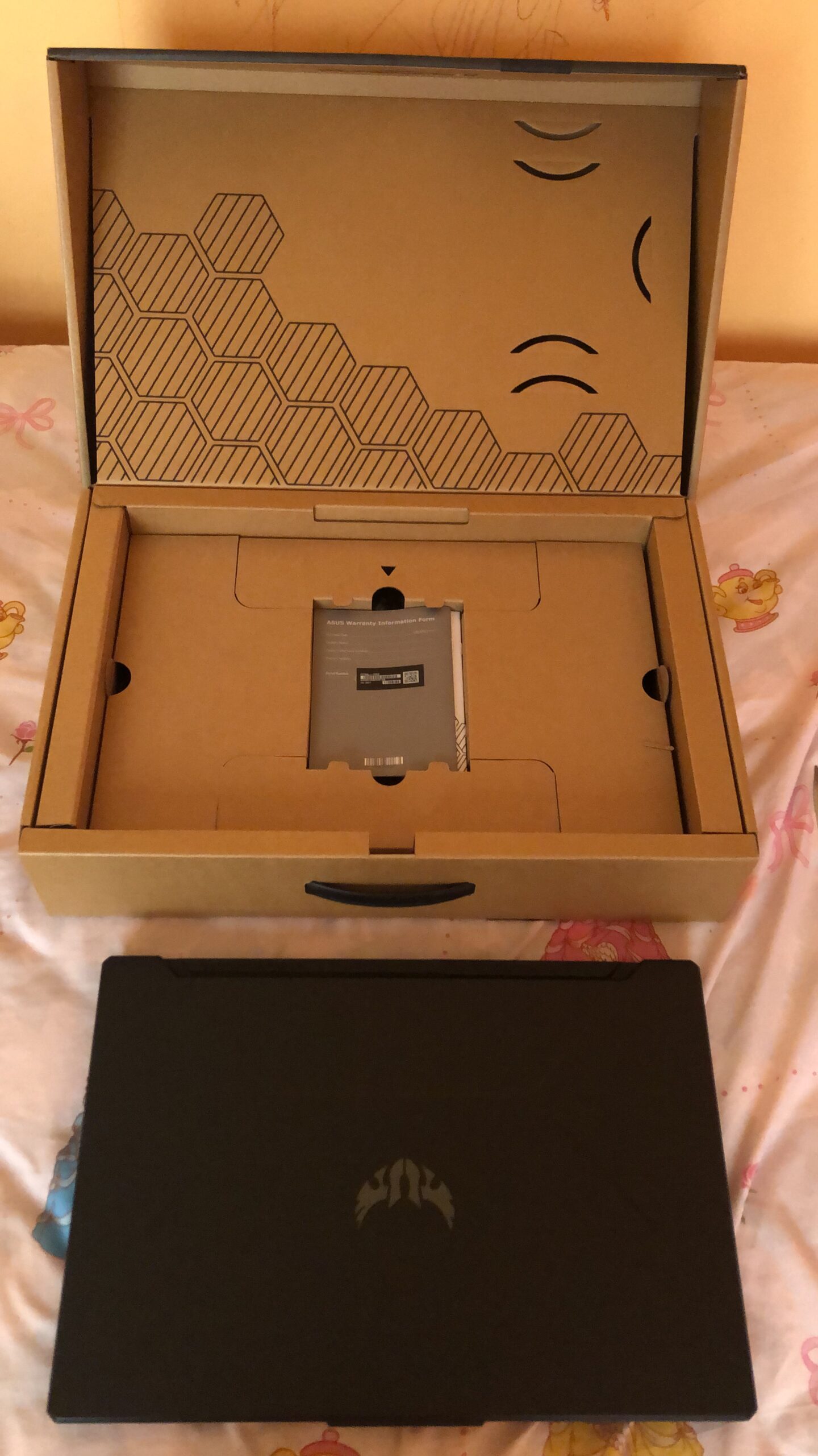
    Opening the Zortrax M200 Plus reveals a well-protected printer surrounded by organized accessories. The package includes the main printer unit, power cable, USB cable, material guide tube, spool holder, perforated build plate, starter tool kit, and comprehensive documentation.

    Notably absent are the side covers, which many users consider essential for optimal printing. Zortrax sells these separately for around $200, a puzzling decision for a premium-priced printer.

    Build quality impresses immediately with the aluminum frame feeling substantial and components fitting together with precision. The attention to detail suggests a machine built for professional use rather than hobbyist tinkering.

    Assembly Process Step-by-Step

    Unlike many 3D printer kits requiring hours of assembly, the Zortrax M200 Plus setup takes approximately 30-45 minutes. The main tasks involve attaching the spool holder, connecting the material guide tube, installing the build plate, and setting up the filament path.

    The most challenging aspect involves installing the optional side panels. Multiple users report frustration with unclear instructions and finicky clips that require patience and proper technique to seat correctly.

    Here’s the basic assembly sequence:

    1. Attach spool holder to the rear mounting points
    2. Connect material guide tube between spool area and extruder
    3. Install perforated build plate on magnetic mounting points
    4. Thread filament through material endstop sensor
    5. Power on and proceed to calibration

    First-Time Calibration and Configuration

    The automatic bed leveling system sets the M200 Plus apart from many competitors. The printer probes multiple points and displays adjustment instructions for the three leveling knobs, making perfect first layers achievable even for beginners.

    Network setup through the touchscreen interface connects to your Wi-Fi network after entering credentials. The printer then appears in Z-Suite software for remote management and file transfers.

    Initial configuration in Z-Suite involves selecting your printer model, choosing material profiles, and adjusting any specific preferences. The software’s clean interface makes this process straightforward, though options remain limited compared to open-source alternatives.

    Print Quality and Real-World Performance Testing

    Standard Test Print Results

    Testing began with the ubiquitous 3D Benchy torture test printed in Z-ABS. The M200 Plus produced exceptionally smooth surfaces with barely visible layer lines, confirming the marketing claims about print quality.

    However, bridging performance proved disappointing. Spans over 20mm showed significant drooping, with longer bridges becoming unusable. This weakness appeared consistently across multiple materials and settings.

    Overhang performance impressed up to 60 degrees, maintaining clean edges without support material. Fine details like text and small features reproduced accurately, benefiting from the precise motion system.

    Material-Specific Performance

    The M200 Plus truly shines when printing with ABS-based materials. The perforated build plate creates exceptional adhesion without glue or tape, while the semi-enclosed design maintains stable temperatures.

    Material Performance Summary:

    • ABS/Z-ABS: Excellent dimensional accuracy, minimal warping
    • PLA/Z-PLA: Good quality but requires removing side panels for cooling
    • PETG/Z-PETG: Reliable printing with proper temperature control
    • TPU/Flexible: Now supported with upgraded extruder design
    • Nylon: Capable but requires careful moisture control

    Engineering materials like glass-filled composites print successfully thanks to the hardened nozzle option. The consistent temperature control proves crucial for these demanding filaments.

    Speed vs Quality Trade-offs

    Standard printing at 100mm/s produces the exceptional quality Zortrax is known for. Surfaces appear almost injection-molded with proper settings, making post-processing minimal for presentation models.

    The Speed Mode firmware update enables printing up to 3x faster, reaching 300mm/s on simple geometries. Quality degradation remains acceptable for prototypes and draft prints, though fine details suffer at maximum speeds.

    For optimal results, consider these speed recommendations:

    • High-detail models: 40-60mm/s
    • Standard quality: 80-100mm/s
    • Draft/prototype: 150-200mm/s
    • Speed Mode maximum: 250-300mm/s

    Zortrax M200 Plus vs M200: Is the Upgrade Worth It?

    Hardware Improvements Breakdown

    The Zortrax M200 Plus vs M200 comparison reveals significant hardware upgrades justifying the newer model. The redesigned extruder incorporates three cooling fans versus the single fan on the M200, improving heat dissipation and enabling flexible filament printing.

    The hotend V3 design prevents common failures like PTFE tube slippage while improving thermal performance. Material feeding geometry changes eliminate filament binding issues that occasionally plagued the original.

    The touchscreen interface transforms user interaction compared to the M200’s small LCD and dial. Navigation feels intuitive, and the ability to preview models before printing reduces errors.

    Feature Additions That Matter

    Several features exclusive to the M200 Plus fundamentally change the user experience. The material endstop sensor pauses printing when filament runs out, saving failed prints from empty spools.

    FeatureM200M200 Plus
    ConnectivityUSB/SD CardWi-Fi/Ethernet/USB
    InterfaceLCD + DialColor Touchscreen
    CameraNoYes
    Material SensorNoYes
    Power RecoveryNoYes
    Flexible MaterialsLimitedFull Support
    Side CoversExtraExtra

    Power loss recovery proves invaluable for long prints, automatically resuming after outages. The built-in camera enables remote monitoring, particularly useful for overnight or weekend prints.

    Price Difference Justification

    The M200 Plus typically costs $400-500 more than a used M200, raising questions about value. For professional users, the productivity features easily justify the premium through reduced failed prints and remote management capabilities.

    Educational institutions benefit from the network connectivity, allowing instructors to manage multiple printers from their desk. The improved reliability means less troubleshooting during critical project deadlines.

    Hobbyists might find the original M200’s lower price more attractive if they don’t need connectivity features. However, the material sensor alone prevents enough failed prints to offset much of the price difference over time.

    Material Compatibility and Z-Suite Software

    Zortrax Ecosystem Materials

    Zortrax offers an extensive line of Zortrax M200 Plus materials optimized for their printers. Each material includes tested profiles in Z-Suite, eliminating guesswork for temperatures and settings.

    Notable options include:

    • Z-ULTRAT: High-strength alternative to standard ABS
    • Z-ASA Pro: UV-resistant for outdoor applications
    • Z-GLASS: Translucent material for lighting applications
    • Z-ESD: Electrostatic discharge protection for electronics
    • Z-SEMIFLEX: Semi-flexible TPU for gaskets and dampeners

    Material quality remains consistently high, with tight diameter tolerances and reliable coloring. Pricing runs higher than generic filaments but often proves worthwhile for critical projects.

    Third-Party Filament Support

    Initially restricted to proprietary materials, Zortrax now embraces third-party filament compatibility. The “external materials” option in Z-Suite software unlocks temperature controls and custom profiles.

    Successfully tested brands include Prusament, Polymaker, and BASF materials. The key involves matching the base material profile (ABS, PLA, PETG) and fine-tuning temperatures for optimal results.

    Creating custom profiles requires patience but enables significant cost savings. Document successful settings for consistency across projects, especially when material properties affect dimensional accuracy.

    Z-Suite Software Deep Dive

    Z-Suite software serves as the exclusive slicer for Zortrax printers, offering a streamlined interface prioritizing ease of use over endless options. The latest version supports multiple file formats including STL, OBJ, 3MF, and DXF.

    Basic controls cover layer height, infill density, support generation, and print speed. Advanced options remain limited compared to PrusaSlicer or Cura, frustrating users wanting granular control.

    The software excels at model repair, automatically fixing common mesh errors that crash other slicers. Multi-printer management shines for production environments, though individual users might find the locked ecosystem restrictive.

    Long-Term Reliability and Maintenance

    Build Quality Assessment

    After extended use, the M200 Plus demonstrates why All3DP named the M200 “Best 3D Printer Workhorse”. The aluminum frame shows no flex or degradation, while linear rails maintain smooth motion after thousands of hours.

    The perforated build plate’s durability impresses, resisting damage from aggressive part removal. Some users report the plate’s connectors wearing over time, though this takes years of daily use.

    Component quality throughout suggests over-engineering rather than cost-cutting. Motors run quietly, belts maintain tension, and the heated bed reaches temperature consistently even after extended use.

    Routine Maintenance Requirements

    The M200 Plus requires surprisingly little maintenance compared to typical desktop printers. The sealed bearings need no lubrication, while the belt tension system rarely requires adjustment.

    Monthly maintenance tasks:

    • Clean build plate with isopropyl alcohol
    • Check belt tension (usually fine)
    • Verify bed leveling (rarely needs adjustment)
    • Clear any debris from extruder fans

    Annual service recommendations:

    • Replace nozzle if print quality degrades
    • Deep clean the hotend assembly
    • Inspect wiring for wear points
    • Update firmware for latest features

    The automatic bed leveling means you’ll spend less time calibrating and more time printing. This reliability makes it ideal for educational settings or small businesses where downtime affects productivity.

    Support and Warranty Coverage

    Zortrax provides a two-year warranty for individual users and one year for businesses, exceeding most competitors. The support website offers comprehensive documentation, video tutorials, and troubleshooting guides.

    Response times for support tickets average 24-48 hours, with most issues resolved through email. The lack of phone support frustrates some users, though the detailed online resources often provide faster solutions.

    Replacement parts remain readily available through official channels and authorized resellers. Common wear items like nozzles, build plates, and hotend assemblies ship quickly when needed.

    Who Should Buy the Zortrax M200 Plus?

    Ideal Use Cases

    The Zortrax M200 Plus price point and features target specific user groups who value reliability over tinkering. Professional designers and engineers appreciate the consistent output quality for client presentations and functional prototypes.

    Perfect for:

    • Engineering firms needing reliable prototype production
    • Schools requiring minimal supervision and maintenance
    • Small businesses producing low-volume parts
    • Medical/dental offices creating custom models
    • Makerspaces wanting dependable shared equipment

    The enclosed design and material compatibility enable printing engineering plastics that open-frame printers struggle with. The 12V battery wiring in the power system provides stable operation even with minor voltage fluctuations.

    When to Choose Alternatives?

    Despite its strengths, the M200 Plus isn’t ideal for everyone. The single extruder limits multi-material prints, while the closed ecosystem frustrates users wanting maximum customization.

    Consider alternatives if you need:

    • Dual extrusion for soluble supports
    • Larger build volume for big parts
    • Open-source software flexibility
    • Budget under $1,500
    • Maximum printing speed over quality

    Hobbyists might find better value in Prusa or Bambu Lab printers offering similar quality at lower prices. The locked software ecosystem particularly limits advanced users wanting to experiment with exotic settings.

    Common Issues and Troubleshooting

    Bridging Problems Solutions

    The M200 Plus’s poor bridging performance requires workaround strategies. Orient parts to minimize unsupported spans, or design with shorter bridge distances when possible.

    For unavoidable bridges, reduce print temperature 5-10°C and increase cooling fan speed to maximum. Slower bridge printing speeds (20-30mm/s) improve results marginally but don’t eliminate the issue entirely.

    Consider redesigning parts with angled overhangs instead of horizontal bridges. The printer handles overhangs well up to 60 degrees, making this a practical solution for many designs.

    Bed Adhesion Management

    While the perforated plate provides exceptional adhesion, sometimes it works too well. Parts can stick so firmly that removal becomes difficult, risking damage to both part and plate.

    Allow the bed to cool completely before attempting removal. The thermal contraction helps release parts naturally. For stubborn prints, place the plate in a freezer for 10-15 minutes to enhance this effect.

    The included spatula works best at low angles, gently working around edges rather than prying upward. Consider printing with a raft for delicate parts, providing a sacrificial layer for removal.

    Network Connectivity Fixes

    Wi-Fi connection issues occasionally frustrate users, particularly with enterprise networks. Ensure your router supports 2.4GHz bands, as the printer doesn’t support 5GHz connections.

    For persistent problems, use Ethernet connections for reliability. The wired connection also improves file transfer speeds for large models, benefiting production environments.

    If Z-Suite fails to discover the printer, verify firewall settings aren’t blocking communication. The software requires specific ports open for printer discovery and camera streaming.

    Print Quality Optimization

    Achieving optimal print quality requires understanding material-specific settings. Start with Zortrax’s proven profiles before attempting modifications, as they’ve tested extensively.

    For improved surface quality, reduce layer height to 0.09mm and slow print speed to 60mm/s. This dramatically increases print time but produces near-injection-molded surface quality.

    Regular nozzle replacement prevents quality degradation over time. Consider keeping spare nozzles for different materials, as switching between materials can accelerate wear.

    Frequently Asked Questions

    What’s the difference between Zortrax M200 and M200 Plus?

    The M200 Plus adds Wi-Fi/Ethernet connectivity, touchscreen interface, built-in camera, material runout sensor, power recovery, improved extruder with three cooling fans, USB storage support, and full flexible filament compatibility. These upgrades transform it from a standalone printer to a connected manufacturing tool worth the price premium for professional users.

    Can I use third-party filaments with the Zortrax M200 Plus?

    Yes, Zortrax now fully supports third-party filaments through the “external materials” option in Z-Suite software. You can adjust temperatures and settings for any standard 1.75mm filament, though Zortrax’s optimized materials often produce superior results with their tested profiles.

    How difficult is the Zortrax M200 Plus setup process?

    The setup takes approximately 30-45 minutes and requires no special tools or technical expertise. The main assembly involves attaching the spool holder, connecting tubes, and installing the build plate. The automatic bed leveling eliminates manual calibration, making it truly plug-and-play.

    Is the Zortrax M200 Plus worth the premium price in 2026?

    For professional users, educational institutions, and small businesses valuing reliability over lowest cost, absolutely. The reduced maintenance, failed print prevention, and remote management capabilities quickly offset the higher initial investment through improved productivity and reduced downtime.

    What materials work best with the Zortrax M200 Plus?

    The printer excels with ABS-based materials thanks to its semi-enclosed design and perforated build plate. Z-ABS, Z-ULTRAT, and Z-ASA Pro produce exceptional results. PETG prints reliably, while PLA requires removing side panels for adequate cooling. The upgraded extruder handles flexible materials like Z-SEMIFLEX well.

    Conclusion: Final Verdict on the Zortrax M200 Plus

    The Zortrax M200 Plus earns its reputation as a professional workhorse through exceptional build quality, reliable operation, and well-integrated smart features. While the premium price and closed ecosystem limit its appeal for hobbyists, the target market of professionals and institutions will find tremendous value.

    Key Strengths:

    • Outstanding print quality with minimal layer lines
    • True plug-and-play operation with automatic calibration
    • Exceptional reliability requiring minimal maintenance
    • Professional connectivity and fleet management
    • Comprehensive material compatibility including flexibles

    Notable Weaknesses:

    • Poor bridging performance requiring design workarounds
    • Premium pricing excludes budget-conscious buyers
    • Locked to Z-Suite software limiting advanced control
    • Side covers sold separately despite being essential
    • Single extruder only (no soluble support options)

    The M200 Plus best serves users prioritizing consistent results over endless tinkering. Engineering firms, schools, and small manufacturers will appreciate the ability to start prints and walk away confidently.

    For those deciding between models, the M200 Plus justifies its premium over the standard M200 through productivity features that prevent failed prints and enable remote management. The inverter generator comparison applies here – paying more upfront for reliability saves money long-term.

    Ready to invest in professional-grade 3D printing? The Zortrax M200 Plus is available through authorized resellers and directly from Zortrax, with educational discounts often available for qualifying institutions.

  • Types of Hand Stitches: Master 10 Essential Techniques

    Types of Hand Stitches: Master 10 Essential Techniques

    Hand stitching forms the foundation of all needlework, whether you’re hemming pants, creating embroidery, or mending tears. Understanding different types of hand stitches empowers you to tackle any sewing project with confidence, from simple repairs to intricate decorative work. These timeless techniques require only a needle, thread, and fabric, making them accessible to everyone regardless of budget or space constraints.

    This comprehensive guide explores 10 types of hand stitches that every sewist should master. You’ll discover essential types of hand stitching techniques for construction, decoration, and finishing work. From the versatile running stitch to the decorative French knot, each technique serves specific purposes in your sewing repertoire. Whether you’re searching for types of stitches for beginners or looking to expand your skills, this guide provides clear instructions and practical applications for each stitch type.

    Quick Answer: 10 Basic Hand Stitches Every Sewist Should Know

    Before diving into detailed instructions, here are the 10 basic hand stitches you’ll learn in this guide:

    1. Running Stitch – The simplest and most versatile basic stitch
    2. Backstitch – Strongest hand stitch for permanent seams
    3. Slip Stitch – Invisible hemming stitch for professional finishes
    4. Blanket Stitch – Decorative edge stitch for blankets and appliqué
    5. Whip Stitch – Quick stitch for joining edges or finishing seams
    6. Catch Stitch – Flexible hemming stitch for stretchy fabrics
    7. Chain Stitch – Decorative stitch perfect for embroidery outlines
    8. French Knot – Dimensional decorative stitch for texture
    9. Cross Stitch – Classic decorative stitch for patterns and designs
    10. Buttonhole Stitch – Reinforced stitch for buttonholes and edges

    Understanding Hand Stitching Basics

    Before exploring specific types of hand stitches, establishing proper technique ensures consistent, professional results. Hand sewing connects you to centuries of textile tradition while offering portability and precision that machines cannot match.

    Essential Tools for Hand Stitching

    Quality tools make hand stitching more enjoyable and efficient. Start with sharp needles in various sizes, matching thread weight to your fabric. A needle threader saves time and frustration, especially when working with fine threads. Keep small scissors handy for trimming threads cleanly.

    Consider investing in a thimble to protect your finger when pushing through tough fabrics. Good lighting prevents eye strain during detailed work. The finer the fabric – the thinner the needle you should use.

    Thread Selection and Preparation

    Choose thread that matches your fabric’s weight and purpose. All-purpose polyester thread works well for most projects, while cotton thread suits natural fabrics. For visible stitching, select thread that complements or contrasts intentionally with your fabric.

    Don’t get the thread too long or it may be prone to tangling while sewing. A good length is around 16 inches after doubled. Waxing your thread prevents tangling and strengthens it for tough fabrics.

    The Running Stitch: Foundation of Hand Sewing

    The running stitch represents the most fundamental of all types of stitches for beginners. This simple in-and-out motion creates everything from temporary basting to permanent seams. Before the invention of the sewing machine, most of the clothes and household textiles in the world were sewn with running stitches!

    How to Execute a Running Stitch?

    Begin by anchoring your thread with a small knot or backstitch. Push the needle through the fabric from back to front, then down again about 1/4 inch away. Continue this rhythm, maintaining consistent stitch length and spacing.

    For efficiency, make several of the running stitches at once, so that it goes faster. Load multiple stitches onto your needle before pulling through, especially with thin fabrics.

    Applications and Variations

    Running stitches excel at:

    • Basting pieces before machine sewing
    • Gathering fabric for ruffles
    • Hand-quilting layers together
    • Creating decorative topstitching
    • Mending tears temporarily

    You can use stem stitch for any line, be it straight or curvy, and also can use it to fill the shapes. Popular embroidery styles like Sashiko and Kantha rely entirely on running stitch variations.

    Backstitch: The Strongest Hand Stitch

    Among all types of hand stitching techniques, the backstitch provides maximum strength for permanent seams. This stitch mimics machine stitching, creating a continuous line of thread on the right side while overlapping on the reverse.

    Creating Perfect Backstitches

    Start with a single forward stitch. For the next stitch, insert your needle backward to the end of the previous stitch, then bring it forward twice the stitch length. This backward-forward motion creates the characteristic strong seam.

    This is a stronger and more secure hand stitch which done with a single thread. The overlapping threads on the back provide exceptional durability for high-stress areas.

    When to Use Backstitch?

    Backstitch excels in situations requiring durability:

    • Securing seams in garments
    • Attaching patches permanently
    • Repairing tears in heavy fabrics
    • Creating strong topstitching
    • Beginning and ending other stitch types

    Professional tailors often use a variation called pick stitch for subtle decorative effects on lapels and edges.

    Slip Stitch: The Invisible Hem

    The slip stitch, also called ladder stitch or blind hem stitch, creates nearly invisible seams perfect for hemming and closing openings. This technique represents one of the most useful 10 different types of stitches for achieving professional finishes.

    Mastering the Slip Stitch Technique

    The needle is pulled through the fold of the hem, then comes out to catch one or two threads, then back into the folded hem. Work from right to left, taking tiny stitches that barely show on the right side.

    Hide your knot inside the fold to start. Pick up only one or two threads from the garment fabric to minimize visibility. Keep stitches small and evenly spaced for the most invisible results.

    Professional Applications

    Slip stitching proves invaluable for:

    • Hemming pants and skirts invisibly
    • Closing pillow openings
    • Attaching linings to garments
    • Finishing bound edges
    • Installing zippers by hand

    This stitch requires patience but delivers couture-quality results worth the effort.

    Blanket Stitch: Decorative and Functional

    The blanket stitch serves dual purposes among types of stitches with pictures often featured in craft projects. Originally designed to finish blanket edges, this stitch now appears frequently in appliqué and decorative work.

    Executing the Blanket Stitch

    Begin at the fabric edge, bringing your needle up from behind. Insert the needle down to the right, then up again directly below, catching the thread loop before pulling tight. This creates the characteristic L-shaped stitch.

    The stitches are spaced at a quarter or half inch apart. Consistent spacing ensures professional-looking results whether finishing edges or creating decoration.

    Creative Uses for Blanket Stitch

    Beyond edge finishing, blanket stitch applications include:

    • Appliqué attachment with decorative flair
    • Buttonhole reinforcement
    • Felt craft assembly
    • Decorative edging on garments
    • Creating textured embroidery fills

    Vary thread weight and color for different effects, from subtle edge protection to bold decorative statements.

    Additional Essential Hand Stitches

    Whip Stitch (Overcast Stitch)

    The whip stitch quickly joins edges or prevents fraying. Working diagonally over the fabric edge, this stitch creates a spiral effect ideal for seaming felt or finishing raw edges. Space stitches evenly, about 1/8 to 1/4 inch apart for best results.

    Catch Stitch (Herringbone Stitch)

    This flexible stitch works perfectly for hemming knits and stretch fabrics. The crossed stitches allow movement without breaking. Work from left to right, alternating small stitches between the hem and garment to create the characteristic zigzag pattern.

    Chain Stitch

    Chain stitch is a key element of zakka embroidery which is very popular nowadays! This decorative stitch creates linked loops perfect for outlining designs or filling spaces with texture. Insert the needle where it emerged, catching the thread loop before pulling through.

    French Knot

    It can be a tiny flower on its own, or pistils, just a “dot” element or a tool for dimensional filling. Master this dimensional stitch by wrapping thread around the needle 1-3 times before inserting it close to the starting point. The knot size varies with thread weight and wrap count.

    Cross Stitch

    This classic decorative stitch forms X-shapes for creating patterns and pictures. Work a row of diagonal stitches in one direction, then return to complete the crosses. Consistent stitch size and tension ensure neat, uniform results.

    Common Mistakes to Avoid

    Learning 10 types of stitches involves recognizing and correcting common errors that plague beginners.

    Thread Length Issues

    Using thread that’s too long causes tangling and weakening. Stick to 18-24 inch lengths for most hand sewing. Replace thread when it shows signs of wear or fraying rather than struggling with damaged thread.

    Inconsistent Tension

    Pulling stitches too tight puckers fabric, while loose stitches appear sloppy. Practice maintaining even tension throughout your work. The fabric should lie flat without distortion when stitching is complete.

    Poor Stitch Spacing

    Uneven spacing immediately reveals amateur work. Use a ruler or marking tool for guidance when learning. With practice, your eye will naturally maintain consistent spacing without aids.

    Pro Tips for Hand Stitching Success

    Creating a Practice Sampler

    Start by making a sampler out of cotton muslin sized 9″ x 11″ and use a ruler and pencil or marker to draw straight lines where your stitches will be. This reference piece helps perfect technique while creating a visual guide for future projects.

    Needle Selection Strategies

    Match needle size to fabric weight and thread thickness. The general rule about the sewing needle selection is, lighter the material, lower number needle is better. Sharp points pierce woven fabrics cleanly, while ballpoint needles prevent snags in knits.

    Thread Preparation Techniques

    Beyond waxing, consider running thread through a fabric softener sheet to reduce static. For slippery threads like silk, a tiny amount of beeswax provides just enough grip without stiffness.

    When to Choose Hand Stitching Over Machine Sewing?

    Understanding when each of these types of hand stitches pdf techniques surpasses machine sewing helps you choose the right method for each task.

    Hand stitching excels for:

    • Precise control in tight spaces
    • Portable projects without electricity
    • Delicate fabrics requiring gentle handling
    • Decorative effects with personality
    • Meditative, relaxing crafting sessions

    While exploring power tools and equipment on sites like FyPower’s buying guides, remember that hand tools often provide superior control for detailed work.

    Frequently Asked Questions About Hand Stitching

    What are the most essential hand stitches for beginners?

    Start with running stitch, backstitch, and slip stitch. These three cover most basic sewing needs from temporary basting to permanent seams and invisible hems. Master these before moving to decorative stitches.

    How do I prevent hand fatigue while stitching?

    Take frequent breaks to stretch your hands and fingers. Use a thimble to reduce finger pressure. Maintain good posture and adequate lighting. Consider ergonomic needle holders for extended stitching sessions.

    Which hand stitch is strongest for repairs?

    Backstitch provides the strongest hold for repairs, especially when doubled. For heavy-duty repairs on items like outdoor gear, consider resources from FyPower’s portable equipment guides for understanding material durability.

    Can I create buttonholes by hand?

    Yes, buttonhole stitch reinforces cut edges perfectly. Mark your buttonhole length, cut carefully, then work buttonhole stitches closely around the opening. This traditional method often outlasts machine buttonholes.

    How do I choose between different hem stitches?

    Select slip stitch for invisible hems on medium-weight fabrics. Use catch stitch for stretchy materials. Blanket stitch works well for decorative hems on casual garments or crafts.

    Master Your Hand Stitching Journey

    Mastering these types of hand stitches opens endless creative possibilities while connecting you to centuries of needlework tradition. Each stitch type serves specific purposes, from sturdy construction to delicate decoration. Practice these 10 basic hand stitches regularly to build muscle memory and confidence.

    Start with simple projects like hemming dish towels or mending small tears. As your skills develop, tackle more complex projects incorporating multiple stitch types. Remember that hand stitching rewards patience with superior control and professional results that machine sewing cannot always achieve. Whether you’re drawn to practical mending or decorative embroidery, these fundamental techniques provide the foundation for all hand sewing endeavors.

    Visit trusted resources like Singer’s sewing guides for additional technique refinements and project inspiration. For those interested in combining traditional crafts with modern technology, explore FyPower’s DIY solar panel installation guides to power your craft room sustainably. Keep practicing these essential stitches, and soon you’ll develop the confidence to tackle any hand sewing challenge with skill and creativity.

  • Bosch vs Dewalt Table Saw | Expert Comparison in 2026

    Bosch vs Dewalt Table Saw | Expert Comparison in 2026

    Choosing between the Bosch 4100XC-10 and Dewalt DWE7491RS table saw can make or break your woodworking projects. Both saws dominate the jobsite table saw market, but which delivers better value for your specific needs?

    The Quick Answer: The Dewalt DWE7491RS excels with its superior 32.5-inch rip capacity and rack-and-pinion fence system, making it ideal for professionals handling large sheet goods. The Bosch 4100XC-10 wins on portability with its gravity-rise stand and lighter weight, perfect for contractors who frequently move between job sites.

    In this comprehensive comparison, we’ll examine every critical aspect of these premium table saws to help you invest wisely. Whether you’re a professional contractor or serious DIY enthusiast, understanding these differences will ensure you choose the tool that matches your workflow perfectly.

    Head-to-Head Specifications Comparison

    Understanding the technical differences between these saws provides the foundation for making an informed decision. Let’s examine how the Bosch 4100XC-10 and Dewalt DWE7491RS stack up in raw specifications.

    Power and Performance Metrics

    Both saws feature 15-amp motors drawing standard 120V power, but their performance characteristics differ significantly. The Dewalt DWE7491RS spins at 4,800 RPM, substantially faster than the Bosch’s 3,650 RPM. This higher speed translates to cleaner cuts in hardwoods and reduced burning on cherry and maple.

    The Bosch compensates with its 4.0 HP motor output, nearly double the Dewalt’s 2.0 HP rating. This extra horsepower becomes crucial when ripping thick hardwoods or pressure-treated lumber. During extended cutting sessions, the Bosch maintains consistent power without bogging down.

    Cutting Capacity Breakdown

    FeatureBosch 4100XC-10Dewalt DWE7491RS
    Right Rip Capacity30 inches32.5 inches
    Left Rip Capacity8.5 inches22 inches
    Depth at 90°3⅛ inches3⅛ inches
    Depth at 45°2¼ inches2¼ inches
    Bevel Range-2° to 47°0° to 45°
    Table Size29″ × 21.5″26.25″ × 22″

    The Dewalt’s impressive 32.5-inch rip capacity handles full sheet goods with room to spare. Meanwhile, its 22-inch left-side capacity proves invaluable for panel work. The Bosch offers a larger overall table surface, providing better support for crosscutting operations.

    Portability and Stand Design Analysis

    Job site portability often determines which saw professionals choose. These two models represent completely different philosophies in mobile table saw design.

    Bosch’s Gravity-Rise Innovation

    The Bosch 4100XC-10’s gravity-rise stand revolutionizes setup efficiency. Simply release the lock and lift – the saw pivots smoothly into position within seconds. The entire unit weighs 60 pounds, making single-person transport manageable.

    The 8-inch pneumatic tires handle rough terrain effortlessly. Unlike standard casters, these wheels maintain stability on gravel, dirt, and uneven surfaces. The stand’s single-lever operation means no fumbling with multiple locks or latches during setup.

    Dewalt’s Four-Leg Stability

    The Dewalt DWE7491RS prioritizes rock-solid stability over quick deployment. Its four-leg design with outward-angled supports creates an incredibly stable platform. At 90 pounds, it requires more effort to transport but rewards users with unwavering performance.

    The telescoping fence rails retract for transport, reducing the footprint significantly. Two fixed wheels and two legs mean the saw stays planted during operation – no accidental rolling when feeding heavy boards. Setup takes slightly longer but provides confidence when handling large materials.

    Fence System Showdown

    The fence system determines cutting accuracy and ease of adjustments. Both manufacturers invested heavily in their fence designs, resulting in two distinct approaches.

    Dewalt’s Rack-and-Pinion Excellence

    The Dewalt DWE7491RS features the gold standard in fence adjustment: a true rack-and-pinion system. Turn the front handle, and both ends move simultaneously with mechanical precision. The micro-adjust knob enables fine-tuning to 1/64-inch accuracy.

    This fence locks parallel every time, eliminating the frustration of manual square-checking. The flip-over design accommodates both standard cuts and narrow rips. Heavy-duty construction resists deflection even when cutting warped lumber.

    Bosch’s SquareLock System

    Bosch’s SquareLock rip fence uses a different approach but achieves similar accuracy. The T-square design references off the front rail, ensuring consistent alignment. While lacking rack-and-pinion smoothness, it provides reliable performance.

    The fence face stands taller than the Dewalt’s, offering better support for vertical cuts. Dual locking points prevent movement during aggressive cuts. Some users report needing occasional adjustments to maintain perfect parallel, unlike the Dewalt’s set-and-forget design.

    Safety Features Comparison

    Modern table saws incorporate numerous safety features beyond basic blade guards. Understanding these differences could prevent serious injuries.

    Blade Guard and Riving Knife Systems

    Both saws include comprehensive guard systems meeting current safety standards. The Dewalt’s tool-free guard removal system stands out – simply pull the release lever for instant access. This convenience encourages users to reinstall guards after dado cuts.

    The Bosch includes anti-kickback pawls integrated into the riving knife assembly. These spring-loaded teeth grip wood if kickback occurs, potentially preventing serious accidents. Both riving knives adjust automatically with blade height, maintaining proper spacing.

    Additional Safety Considerations

    The Bosch 4100XC-10 features Smart Guard System technology with independent side guards. These modular components improve visibility while maintaining protection. The included push stick stores onboard, ensuring it’s always within reach.

    Dewalt’s safety paddle switch prevents accidental activation better than traditional buttons. The large, red surface stops the blade quickly when bumped. Both saws include blade brakes, though the Bosch’s stops approximately one second faster.

    Real-World Performance Testing

    Laboratory specifications tell only part of the story. How do these saws perform during actual woodworking tasks?

    Ripping Operations

    The Dewalt DWE7491RS excels when ripping sheet goods thanks to its extended capacity and smooth fence adjustments. Processing full plywood sheets becomes effortless with 32.5 inches of support. The higher blade speed produces glass-smooth edges requiring minimal sanding.

    The Bosch 4100XC-10 demonstrates superior power when ripping thick hardwoods. Its 4HP motor maintains speed through 8/4 oak without hesitation. The larger table surface provides better control during these demanding cuts.

    Cross-Cutting Performance

    Both saws handle crosscuts adequately, though neither matches a sliding compound miter saw’s precision. The Bosch’s larger table and included outfeed support excel here. Its gravity-rise stand positions the table at comfortable working height.

    The Dewalt’s miter gauge disappoints many users, suffering from excessive play. Aftermarket replacements like Incra or Kreg models transform crosscutting accuracy. The Bosch gauge performs marginally better but still benefits from upgrading.

    Build Quality and Durability Assessment

    Long-term reliability separates professional tools from homeowner models. Both manufacturers engineered these saws for job site abuse.

    Construction Materials and Design

    The Bosch 4100XC-10 uses cast aluminum for critical components, balancing weight and strength effectively. The table remains flat after years of use, resisting warpage from temperature changes. All adjustment mechanisms use metal gearing rather than plastic.

    Dewalt constructs the DWE7491RS with heavy-gauge steel throughout. This adds weight but ensures decades of reliable service. The powder-coated finish resists scratches and corrosion better than painted alternatives.

    Component Quality Analysis

    Both saws feature industrial-grade bearings and arbor assemblies. The Dewalt’s higher RPM design required upgraded bearings, which should outlast the motor. Bosch includes dual capacitors for reliable starting under load.

    Switch quality favors Dewalt’s sealed design, preventing sawdust infiltration. The Bosch switch, while functional, may require cleaning after extended use. Both manufacturers offer comprehensive parts availability for repairs.

    Price and Value Proposition

    Investment in quality tools requires careful consideration of long-term value beyond initial purchase price.

    Initial Cost Comparison

    The Dewalt DWE7491RS typically costs $50-100 more than the Bosch 4100XC-10. This premium reflects the superior fence system and greater rip capacity. Both saws frequently appear in promotional bundles with stands included.

    Consider total ownership costs including blades, accessories, and potential repairs. Both manufacturers support their products with multi-year warranties. Dewalt offers a 90-day money-back guarantee, demonstrating confidence in their design.

    Long-Term Value Analysis

    Professional contractors often recoup the Dewalt’s higher price through increased productivity. The time saved adjusting the fence and handling large materials adds up quickly. The fence system alone justifies the premium for cabinet shops.

    The Bosch provides exceptional value for contractors prioritizing portability. Its lower weight reduces vehicle wear and worker fatigue. The quicker setup time means more billable hours on site rather than equipment deployment.

    User Experience and Ergonomics

    Daily comfort and ease of use significantly impact job satisfaction and productivity. These saws approach ergonomics differently.

    Control Placement and Accessibility

    The Dewalt positions all primary controls within easy reach from the operator position. Fence adjustments, blade height, and bevel controls require minimal movement. The paddle switch location feels natural during operation.

    Bosch scattered controls slightly more, though still maintaining good accessibility. The blade height wheel’s position requires reaching across the table occasionally. However, the soft-start feature reduces startup torque, improving control.

    Noise and Vibration Levels

    The Bosch 4100XC-10’s soft-start circuitry and lower RPM produce noticeably less noise. Extended use proves less fatiguing compared to the Dewalt’s higher-pitched whine. Both saws benefit from quality ear protection regardless.

    Vibration dampening favors the heavier Dewalt when properly set up. Its four-point stance absorbs cutting forces effectively. The Bosch’s two-wheel design transmits more vibration through the frame during heavy cuts.

    Maintenance Requirements

    Understanding maintenance needs helps budget time and resources appropriately. Both saws require regular attention for optimal performance.

    Routine Maintenance Tasks

    Clean the blade elevation and bevel mechanisms monthly to prevent binding. Both saws accumulate sawdust in these areas despite dust collection efforts. The Dewalt’s sealed bearing design requires less frequent lubrication.

    Check fence alignment quarterly using a reliable square. The Bosch may need minor adjustments over time, while the Dewalt typically maintains settings longer. Both manufacturers provide detailed adjustment procedures in their manuals.

    Common Issues and Solutions

    The Bosch 4100XC-10 occasionally develops play in the blade elevation mechanism. Tightening the worm gear assembly usually resolves this issue. Some users report the soft-start capacitor failing after several years.

    Dewalt DWE7491RS owners sometimes experience fence binding due to sawdust accumulation. Regular cleaning with compressed air prevents this problem. The higher RPM motor may require brush replacement sooner than the Bosch.

    Best Use Cases for Each Saw

    Matching the tool to your specific needs ensures satisfaction and productivity. Each saw excels in different scenarios.

    When to Choose the Bosch 4100XC-10?

    Select the Bosch for frequent job site moves where setup speed matters. Residential contractors appreciate the lighter weight when navigating stairs. The superior power handling makes it ideal for hardwood flooring installers.

    Small shop owners benefit from the Bosch’s compact storage footprint. The gravity-rise stand folds more compactly than the Dewalt’s four-leg design. Weekend warriors find the price point and features perfectly balanced.

    When to Choose the Dewalt DWE7491RS?

    The Dewalt becomes essential when regularly processing sheet goods. Cabinet makers and finish carpenters need the extended rip capacity daily. The superior fence system saves hours of adjustment time over the saw’s lifetime.

    Professional framers appreciate the rock-solid stability when cutting treated lumber. The left-side capacity handles panel saw duties adequately. High-volume shops benefit from the fence system’s repeatability.

    Common Mistakes to Avoid

    Learning from others’ experiences prevents costly errors and frustration. Avoid these common mistakes when purchasing and using either saw.

    Purchase Decision Pitfalls

    Don’t assume higher RPM always means better performance – the Bosch’s torque often matters more. Avoid choosing based solely on rip capacity if you rarely cut wide materials. Consider your vehicle’s capacity before selecting the heavier Dewalt.

    Skipping the stand to save money usually backfires. Both saws perform best with their designed stands. Aftermarket options rarely match the convenience and stability of factory stands.

    Setup and Usage Errors

    Never operate without proper dust collection – both motors suffer from sawdust infiltration. Avoid over-tightening the blade, which stresses the arbor assembly. Check blade alignment after transport, as vibration can affect settings.

    Don’t neglect the owner’s manual setup procedures. Both saws require careful initial alignment for optimal performance. Skipping these steps leads to accuracy problems and premature wear.

    Professional Tips and Tricks

    Maximize your investment with these insider techniques developed by experienced users.

    Performance Enhancement Strategies

    Upgrade to a quality combination blade immediately – stock blades disappoint on both saws. Thin-kerf blades reduce motor strain and improve cut quality. Consider dedicated rip and crosscut blades for best results.

    Add aftermarket zero-clearance inserts to reduce tear-out. Both saws accept shop-made inserts easily. Create multiple inserts for different blade angles and dado sets.

    Workshop Integration Ideas

    Mount a router table in the extension wing for space-saving versatility. Both saws’ sturdy frames support this modification well. Add auxiliary fences for repetitive cuts without disturbing the main fence setting.

    Install aftermarket dust collection upgrades for cleaner operation. The Dewalt’s dust port accepts standard 2.5-inch hoses directly. The Bosch may require an adapter but achieves better collection with modifications.

    Frequently Asked Questions

    Can either saw handle dado blade sets?

    Both saws accept standard 8-inch dado sets up to 13/16-inch width. The Dewalt explicitly supports dado operations, while Bosch recommends checking arbor length. Most users report success with both saws using quality dado sets.

    Which saw works better with aftermarket accessories?

    The Dewalt’s standard miter slots accept more aftermarket sleds and jigs. The Bosch uses slightly non-standard dimensions, requiring modification of some accessories. Both accept standard 10-inch blades without issues.

    How do these saws compare to SawStop models?

    Neither includes flesh-sensing technology like SawStop. However, both cost significantly less while providing professional-grade performance. Users prioritizing safety above all else should consider SawStop’s unique protection.

    Can I run either saw on a standard 15-amp circuit?

    Yes, both saws operate on standard 120V, 15-amp household circuits. However, dedicated circuits prevent nuisance breaker trips during startup. Avoid extension cords under 12-gauge for best performance.

    Which saw handles wet or pressure-treated lumber better?

    The Bosch’s higher torque motor excels with wet lumber. Its lower RPM reduces blade binding in resinous woods. Both saws require frequent blade cleaning when cutting treated materials.

    Do these saws require 220V power for optimal performance?

    No, both saws are designed specifically for 120V operation. Unlike cabinet saws, they achieve full rated power on standard circuits. This portability makes them ideal for job site use.

    How long do the motors typically last?

    With proper maintenance, expect 5-10 years of professional use. The Bosch’s lower RPM design may extend motor life slightly. Both manufacturers offer replacement motors if needed.

    Which fence system stays accurate longer?

    The Dewalt’s rack-and-pinion mechanism maintains accuracy better over time. Its mechanical design resists wear compared to friction-based systems. Users report minimal adjustment needs after years of service.

    Final Verdict: Making Your Choice

    Both the Bosch 4100XC-10 and Dewalt DWE7491RS represent excellent investments in professional-grade equipment. Your specific needs should drive the final decision.

    Choose the Dewalt DWE7491RS if you prioritize cutting capacity, fence precision, and stability. Cabinet makers, finish carpenters, and high-volume shops benefit most from its features. The superior fence system alone justifies the premium for many professionals.

    Select the Bosch 4100XC-10 when portability and power matter most. Contractors moving between sites daily appreciate the weight savings and instant setup. The exceptional motor torque handles demanding materials that would challenge the Dewalt.

    Take Action Today

    Ready to upgrade your workshop with professional-grade precision? Both saws transform woodworking capabilities when matched to appropriate needs. Consider your typical projects, workspace constraints, and mobility requirements.

    Visit FyPower’s generator guides for more insights on powering your tools on remote job sites. For detailed table saw comparisons and expert reviews, check out Pro Tool Reviews’ comprehensive testing.

    Invest in the right tool today – your future projects will thank you. Whether you choose Bosch or Dewalt, either saw provides years of reliable service when properly maintained. Stop compromising with inadequate equipment and experience the difference professional tools make.Remember to explore FyPower’s maintenance guides to keep all your power equipment running smoothly. For additional woodworking insights and table saw expertise, Family Handyman’s expert reviews offer valuable perspectives from seasoned professionals.

  • Raft vs Brim vs Skirt: Which 3D Print Method? | Guide 2026

    Raft vs Brim vs Skirt: Which 3D Print Method? | Guide 2026

    Picture this: You’ve spent hours preparing the perfect 3D model, your printer is calibrated, and you hit print. Hours later, you return to find a tangled mess of filament instead of your masterpiece. Sound familiar?

    Poor bed adhesion is the silent killer of 3D prints, wasting both time and precious filament. But here’s the good news: choosing the right adhesion method can transform your success rate from frustrating to fantastic.

    The difference between rafts, brims, and skirts is simple: rafts create a full platform beneath your print, brims extend only from the edges, and skirts don’t touch the print at all. Each serves a unique purpose in ensuring perfect first layers.

    This guide will save you filament, reduce failures, and help you achieve professional results every time. We’ll explore detailed definitions, head-to-head comparisons, optimal settings for each method, and troubleshooting tips that actually work.

    Quick Answer: What’s the Difference Between Raft, Brim, and Skirt?

    30-Second Summary

    Need answers fast? Here’s everything you need to know about brim vs raft 3d printing methods:

    FeatureRaftBrimSkirt
    Contact with PrintFull base coverageEdge contact onlyNo contact
    Layers3-6 layers1 layer1-3 layers
    Adhesion StrengthMaximumModerateNone (indirect)
    Filament UsageHigh (+30%)MediumMinimal
    Removal DifficultyModerateEasyN/A
    Best ForWarping materials, small basesCorner lifting, medium adhesionNozzle priming, bed checking

    Key Differences at a Glance

    The difference between skirt and brim comes down to contact. Brims physically attach to your print’s first layer, expanding its footprint. Skirts maintain a set brim distance between the print and themselves, typically 3-5mm.

    Rafts take adhesion to the extreme by creating a thick foundation that covers the entire print base. This multi-layer approach provides maximum stability but requires careful separation distance calibration.

    Each method excels in specific scenarios. Understanding these differences means fewer failed prints and optimized material usage.

    Which Should You Choose? (Decision Tree)

    Follow this simple decision process:

    1. Is your print material prone to warping? (ABS, Nylon)
      • Yes → Use a RAFT
      • No → Continue to #2
    2. Does your print have a small footprint or tall profile?
      • Yes → Use a RAFT
      • No → Continue to #3
    3. Are you experiencing corner lifting with current prints?
      • Yes → Use a BRIM
      • No → Continue to #4
    4. Is bed adhesion generally good?
      • Yes → Use a SKIRT
      • No → Use a BRIM

    What is a Raft in 3D Printing?

    How Rafts Work: The Complete Platform Solution

    A raft is essentially a disposable foundation for your 3D print. Think of it as building a house on a concrete slab rather than directly on soil. This thick, multi-layer platform adheres strongly to the build plate while providing a stable base for your actual print.

    The brim vs raft pattern difference is significant. While brims create a thin perimeter extension, rafts build upward with multiple layers. This creates a buffer zone between your print and any bed imperfections.

    Rafts excel when printing with challenging materials or dealing with less-than-perfect print surfaces. They compensate for minor bed leveling issues and provide consistent first-layer quality.

    Anatomy of a 3D Printing Raft

    Understanding raft structure helps optimize your settings:

    Base Layers (2-3 layers):

    • Printed slowly with thick layer heights (0.3-0.4mm)
    • Maximum bed contact for strong adhesion
    • Often printed at higher temperatures

    Interface Layers (1-2 layers):

    • Bridge between base and top layers
    • Moderate speed and layer height
    • Creates the separation gap for easy removal

    Top Layers (2-3 layers):

    • Smooth surface for print adhesion
    • Normal layer height matching your print
    • Determines bottom surface quality

    Why Rafts Use 30% More Filament (But When It’s Worth It)

    The extra material investment in rafts pays dividends in specific situations. Yes, you’ll use approximately 30% more filament compared to skirts vs brims, but consider the alternative: a failed 10-hour print wastes far more.

    Rafts are worth the extra filament when:

    • Printing with ABS or other warp-prone materials
    • Working with perforated or textured build surfaces
    • Creating tall, narrow objects prone to toppling
    • Dealing with persistent adhesion failures

    The key is using rafts strategically, not as a default for every print.

    What is a Brim in 3D Printing?

    Understanding Brims: Your First Layer’s Best Friend

    A brim is a single-layer skirt that actually touches your print. Imagine the brim of a hat extending outward from the crown – that’s exactly what a 3D printing brim does for your model’s base.

    Unlike the difference between skirt and raft options, brims strike a perfect balance. They increase the first layer’s surface area without adding significant height or complexity. This makes them ideal for prints that need just a bit more grip.

    Brims typically extend 3-8mm from your print’s edge, though this is highly customizable. The wider the brim, the stronger the adhesion, but also the more post-processing required.

    Brim vs Raft Pattern: The Key Structural Differences

    The structural difference between brims and rafts impacts both function and removal:

    Brim Structure:

    • Single layer only (matches first layer height)
    • Extends horizontally from print edges
    • No vertical separation from print
    • Connected via perimeter lines

    Raft Structure:

    • Multiple layers (5-6 typical)
    • Extends under entire print base
    • Includes engineered separation gap
    • Grid or linear infill pattern

    This fundamental difference means brims are easier to remove but provide less dramatic adhesion improvement than rafts.

    Inner vs Outer Brims: Which Type Do You Need?

    Most users only know about outer brims, but inner brims serve specific purposes:

    Outer Brims:

    • Standard brim type
    • Extends outward from print
    • Best for general adhesion improvement
    • Easy to remove with minimal scarring

    Inner Brims:

    • Fill holes within the print’s first layer
    • Useful for prints with large internal gaps
    • Prevent curling in hollow sections
    • More challenging to remove completely

    Some slicers like PrusaSlicer offer both options, letting you customize based on your model’s geometry.

    What is a Skirt in 3D Printing?

    The Multi-Purpose Skirt: More Than Just a Line

    Despite being the simplest bed adhesion option, skirts serve multiple critical functions. A skirt is one or more loops of filament printed around your model without making contact – think of it as a practice run for your printer.

    The primary purpose isn’t adhesion at all. Instead, skirts prime your nozzle, establish consistent flow, and give you a chance to spot problems before they affect your actual print.

    Many beginners overlook skirts, but experienced makers know they’re invaluable for print preparation and diagnostics.

    Skirts vs Brims: Why Distance Matters

    The difference between a skirt and brim boils down to one parameter: offset distance. Set this to zero, and your skirt becomes a brim. Increase it to 3-5mm, and you have a traditional skirt.

    This distance serves several purposes:

    • Prevents accidental adhesion to the model
    • Creates space for nozzle cleaning
    • Allows for thermal expansion without contact
    • Provides room for ooze collection

    Standard skirt offset is 3mm, but increase this for larger nozzles or materials prone to stringing.

    Advanced Skirt Functions: Draft Shields and Ooze Shields

    Skirts can do more than just prime your nozzle:

    Draft Shield Mode:

    • Print skirt as tall as your object
    • Creates a thermal barrier around the print
    • Essential for ABS in open-air printers
    • Reduces warping from air currents

    Ooze Shield Mode:

    • Used with dual-extruder printers
    • Catches material from inactive nozzle
    • Prevents color contamination
    • Maintains clean print surfaces

    These advanced applications transform the humble skirt into a powerful printing tool.

    When to Use Each Adhesion Method: A Practical Guide

    Material-Specific Recommendations

    Different materials have vastly different adhesion requirements:

    High-Warp Materials (Use RAFT):

    • ABS: Almost always needs a raft
    • Nylon: Raft essential for stability
    • PC (Polycarbonate): Maximum adhesion required

    Medium-Adhesion Materials (Use BRIM):

    • PETG: Brim prevents corner lifting
    • ASA: Similar to ABS but brim often sufficient
    • TPU: Brim helps with flexible material challenges

    Easy-Adhesion Materials (Use SKIRT):

    • PLA: Usually only needs skirt
    • PLA+: Good bed adhesion naturally
    • SILK filaments: Skirt for priming only

    Print Geometry Considerations

    Your model’s shape dramatically impacts adhesion needs:

    Small Footprints (<20mm²):

    • Always use raft for stability
    • Tall objects especially vulnerable
    • Consider increasing raft margin

    Large Flat Surfaces:

    • Brim usually sufficient
    • Watch for corner lifting
    • 5-10 brim lines recommended

    Complex First Layers:

    • Multiple small contact points need rafts
    • Intricate designs benefit from full support
    • Text or fine details print better on rafts

    Printer and Bed Condition Factors

    Your hardware setup influences adhesion choices:

    Textured/PEI Beds:

    • Generally need less adhesion help
    • Skirts often sufficient for PLA
    • Brims for challenging materials

    Glass Beds:

    • Smooth surface may need more help
    • Brims standard for most prints
    • Rafts for problematic materials

    Damaged/Uneven Beds:

    • Rafts compensate for imperfections
    • Avoid relying on skirts alone
    • Consider bed replacement long-term

    Optimal Settings for Rafts, Brims, and Skirts

    Raft Settings Explained

    Master these critical raft parameters for perfect results:

    Separation Distance (Z Gap):

    • Default: 0.1mm
    • Increase for easier removal (0.15-0.2mm)
    • Decrease for better adhesion (0.05-0.08mm)
    • Adjust based on material properties

    Layer Configuration:

    • Base layers: 2-3 (more for uneven beds)
    • Top layers: 2-3 (more for smoother bottom surface)
    • Base layer height: 0.3-0.4mm
    • Top layer height: Match print layer height

    Print Speeds:

    • Base layer: 15-20mm/s (slow for adhesion)
    • Interface layers: 25-30mm/s
    • Top layers: Match first layer speed
    • Never exceed 50% of normal print speed

    Brim Configuration Guide

    Optimize your brim settings for reliable adhesion:

    Brim Line Count:

    • Minimum: 3-5 lines for small prints
    • Standard: 5-10 lines for medium adhesion
    • Maximum: 15-20 lines for challenging prints
    • Each line adds ~0.4mm width (with 0.4mm nozzle)

    Brim Width Calculation:

    • Formula: Line Count × Nozzle Diameter
    • Example: 10 lines × 0.4mm = 4mm brim
    • Adjust based on bed adhesion quality

    Special Parameters:

    • Brim offset: 0mm (touching) to 0.1mm (slight gap)
    • Interior brim: Enable for hollow prints
    • Brim layer height: Always match first layer

    Skirt Parameters for Different Uses

    Configure skirts based on intended function:

    Basic Priming Setup:

    • Loops: 2-3
    • Distance: 3-5mm from object
    • Height: 1 layer
    • Minimum extrusion: 5-10mm

    Draft Shield Configuration:

    • Loops: 1-2
    • Distance: 5-10mm
    • Height: Match object height
    • Speed: Normal print speed

    Diagnostic Settings:

    • Loops: 3-5 (more for bed leveling checks)
    • Distance: 10-15mm (easier observation)
    • Height: 1 layer
    • Speed: Slow (50% first layer speed)

    Slicer-Specific Settings

    Each slicer implements these features slightly differently:

    Cura Settings Location:

    • Build Plate Adhesion Type → Dropdown menu
    • All settings under “Build Plate Adhesion”
    • Advanced settings visible in custom mode

    PrusaSlicer Approach:

    • Print Settings → Skirt and Brim
    • Separate tabs for each feature
    • More granular control options

    Simplify3D Configuration:

    • Additions tab → Choose adhesion type
    • Separate processes possible
    • Custom adhesion shapes supported

    Detailed slicer guides available from All3DP.

    Removal Techniques: Clean Results Every Time

    Safe Raft Removal Without Damaging Your Print

    Removing rafts requires patience and proper technique:

    Step-by-Step Raft Removal:

    1. Let print cool completely (prevents warping)
    2. Start at a corner with thin tool
    3. Work slowly around perimeter
    4. Lift gradually, not forcefully
    5. Clean residue with 400-grit sandpaper

    Recommended Tools:

    • Thin metal spatula or paint scraper
    • Deburring tool for stubborn sections
    • Needle-nose pliers for grip
    • Sandpaper for finishing

    Pro Tip: If rafts consistently fuse to prints, increase separation distance by 0.05mm increments.

    Brim Removal: Tools and Techniques

    Brims are easier to remove but still require care:

    Best Practices:

    • Remove while print is slightly warm (40-50°C)
    • Pull at 45-degree angle
    • Use flush cutters for clean edges
    • Work in sections for large brims

    Quick Removal Method:

    1. Score brim at attachment point
    2. Bend outward gently
    3. Snap off in controlled sections
    4. Clean edges with deburring tool

    Post-Processing Tips for Professional Finishes

    Transform your prints from good to great:

    After Raft Removal:

    • Sand with progressive grits (220→400→800)
    • Use primer for painting preparation
    • Consider vapor smoothing for ABS

    After Brim Removal:

    • Deburr all edges carefully
    • Use craft knife for precision
    • Heat gun for minor imperfections

    General Finishing:

    • Remove strings with heat gun
    • Fill gaps with appropriate filler
    • Prime before painting for best results

    Troubleshooting Common Adhesion Problems

    When Rafts Won’t Stick: 5 Quick Fixes

    Raft adhesion failures need immediate attention:

    1. Level Your Bed Properly
      • Use paper method or auto-leveling
      • Check all corners and center
      • Re-level after temperature changes
    2. Increase Bed Temperature
      • Add 5-10°C above normal
      • ABS: 110°C minimum
      • PETG: 80-85°C optimal
    3. Slow Down First Layer
      • Reduce to 10-15mm/s
      • Slower = better adhesion
      • Increase after base layers
    4. Clean the Build Surface
      • Isopropyl alcohol (90%+)
      • Remove all fingerprints
      • Consider adhesion aids
    5. Adjust Z-Offset
      • Slightly closer to bed
      • Watch for first layer squish
      • Fine-tune in 0.02mm steps

    Brim Lifting at Corners: Solutions

    Corner lifting indicates insufficient adhesion:

    Immediate Solutions:

    • Increase brim width to 15-20 lines
    • Add mouse ears (corner discs)
    • Reduce cooling for first layers
    • Shield from drafts

    Environmental Fixes:

    • Enclose printer if possible
    • Block air conditioning vents
    • Maintain stable room temperature
    • Use draft shields for tall prints

    Skirt Not Priming Properly: Diagnosis Guide

    Poor skirt extrusion reveals underlying issues:

    Common Causes:

    • Nozzle too far from bed
    • Partial clog present
    • Incorrect temperature
    • Moisture in filament

    Diagnostic Steps:

    1. Check nozzle distance first
    2. Perform cold pull if needed
    3. Verify temperature settings
    4. Dry filament if necessary

    Pro Tips: Advanced Adhesion Strategies

    Combining Methods for Challenging Prints

    Sometimes one method isn’t enough:

    Raft + Skirt Combo:

    • Use skirt to prime before raft
    • Helps with color changes
    • Ensures consistent raft quality

    Brim + Mouse Ears:

    • Standard brim plus corner discs
    • Maximum corner adhesion
    • Minimal extra material use

    Variable Adhesion Zones:

    • Different methods for different parts
    • Requires advanced slicer features
    • Teaching Tech has excellent tutorials

    Custom Adhesion Patterns in Advanced Slicers

    Go beyond standard options:

    Custom Brim Shapes:

    • Design specific patterns in CAD
    • Import as separate STL
    • Print as single-layer addition

    Selective Raft Areas:

    • Only under problem zones
    • Saves material significantly
    • Requires modifier meshes

    Material-Saving Techniques Without Sacrificing Quality

    Optimize adhesion with minimal waste:

    Smart Raft Design:

    • Reduce margin to 2-3mm
    • Fewer base layers for good beds
    • Increase separation slightly

    Efficient Brim Usage:

    • Variable width based on geometry
    • Skip brim on well-adhering sections
    • Use interior brim only when needed

    Skirt Optimization:

    • Single loop for simple priming
    • Reduce distance to 2mm
    • One layer unless draft shield needed

    Cost Analysis: Filament Usage and Time Comparison

    Real Numbers: How Much Extra Filament Does Each Method Use?

    Let’s break down actual costs for a 50mm cube print:

    Adhesion TypeExtra FilamentCost (@ $20/kg)% Increase
    Skirt (3 loops)0.5g$0.012%
    Brim (8mm)2.5g$0.0510%
    Raft (standard)7.5g$0.1530%

    For a typical 100g print, raft adds $3 in material costs. Compare this to reprinting after failure!

    Time Investment: Print Duration Differences

    Time impacts are often overlooked:

    Additional Print Time:

    • Skirt: 1-2 minutes
    • Brim: 5-10 minutes
    • Raft: 15-30 minutes

    Removal Time:

    • Skirt: 0 minutes (no removal)
    • Brim: 2-5 minutes
    • Raft: 5-15 minutes

    Factor both into your workflow planning.

    ROI Calculator: Failed Prints vs. Adhesion Aid Costs

    Simple math reveals the truth:

    Failure Cost Calculation:

    • Average print: 50g filament ($1)
    • Print time: 4 hours
    • Electricity: $0.50
    • Total loss per failure: $1.50 + time

    Break-even Analysis:

    • Raft cost: $0.15
    • Prevents failure rate: 20% → 5%
    • ROI: 10 rafts = 3 prevented failures
    • Net savings: Significant

    Frequently Asked Questions

    Can I use a raft and brim together?

    Technically possible but rarely beneficial. Rafts already provide maximum adhesion, making brims redundant. The only exception might be experimental materials with extreme warping tendencies.

    Most slicers won’t allow both simultaneously anyway. Choose the stronger option (raft) when in doubt.

    Why does my raft fuse to the print?

    Fusion occurs when separation distance is too small. Common causes include:

    • Z-gap set below 0.1mm
    • Printing temperature too high
    • First layer over-squished
    • Material prone to strong layer adhesion

    Increase separation distance by 0.05mm and reduce print temperature by 5°C.

    What’s the difference between skirt and brim distance settings?

    The settings control the same parameter – offset from the model. The difference between them is that:

    • Skirt distance: Typically 2-10mm (no contact intended)
    • Brim distance: Always 0mm (must touch model)

    Some slicers call this “offset” or “gap” instead of distance.

    Do resin printers use rafts, brims, or skirts?

    Resin printing uses different adhesion methods entirely. Instead of these FDM techniques, resin printers use:

    • Supports (similar function to rafts)
    • Burn-in layers (extra exposure for adhesion)
    • Lift speed adjustments

    The concepts don’t translate directly between technologies.

    How do I know if I need bed adhesion help?

    Watch for these warning signs:

    • Corners lifting during printing
    • First layer not sticking uniformly
    • Prints detaching mid-print
    • Inconsistent first layer width
    • Previous failures with similar geometry

    When in doubt, start with a brim – it’s the best balance of effectiveness and efficiency.

    Conclusion

    Mastering the difference between rafts, brims, and skirts transforms your 3D printing success rate. Each method serves a unique purpose: rafts provide bombproof adhesion for challenging prints, brims offer balanced support with easy removal, and skirts handle priming and diagnostics.

    The key to success lies in matching the method to your specific situation. Consider your material, geometry, and printer setup when choosing. Remember that using extra filament for adhesion is always cheaper than reprinting failed projects.

    Start with these recommended settings, then fine-tune based on your results. Every printer is slightly different, and experience will teach you when to use each technique.

    Your next print deserves the right foundation. Choose wisely, print confidently, and enjoy consistent first-layer perfection. The difference between frustration and success is often just a matter of selecting the right bed adhesion method.

  • 3D Printing Shell Thickness Guide | Charts & Settings | 2026

    3D Printing Shell Thickness Guide | Charts & Settings | 2026

    Getting your shell thickness wrong is the fastest way to turn a promising 3D print into expensive plastic waste. Yet most beginners overlook this critical setting, focusing instead on temperature and speed while their prints fail from the inside out.

    The optimal 3D printing shell thickness ranges from 0.8mm to 2.0mm, with a universal rule of using at least 2 nozzle diameters for your wall thickness for 3D printing. For a standard 0.4mm nozzle, this means a minimum of 0.8mm walls, though 2.0mm delivers the best balance of strength and efficiency.

    Wrong shell settings cause weak parts that snap under pressure, excessive material waste that doubles your costs, and surface defects that ruin your finish. But with the right knowledge, you can optimize these settings for any DIY project.

    This guide covers everything from basic settings and material-specific charts to advanced troubleshooting techniques. You’ll learn to calculate perfect wall thickness, optimize for different technologies, and solve common problems that plague even experienced makers.

    What Is 3D Printing Shell Thickness?

    Shell thickness, often called wall thickness, refers to the outer perimeter layers of your 3D printed object. These layers form the external structure that defines your part’s shape, strength, and appearance.

    Think of shells as the skin of your print. While infill provides internal support, shells create the actual surfaces you see and touch. They determine how robust your part feels and how well it resists external forces.

    The shell consists of vertical walls around the sides and horizontal layers on the top and bottom. Together, these elements create a protective barrier that encases the infill pattern and gives your print its final form.

    Shell vs. Wall Thickness: Understanding the Terminology

    Many people use “shell thickness” and “wall thickness” interchangeably, but there’s a subtle distinction. Wall thickness specifically refers to the vertical perimeters, while shell thickness encompasses both walls and top/bottom layers.

    In most slicing software, you’ll find separate settings for wall thickness and top/bottom thickness. Cura uses “Wall Thickness,” PrusaSlicer calls it “Perimeters,” and Simplify3D labels it “Outline/Perimeter Shells.”

    The key measurement remains consistent: shells are measured in millimeters or as a count of lines. A 3d print wall thickness chart typically shows both values to help you convert between them based on your nozzle size, similar to how generator manuals specify exact measurements for optimal performance.

    How Shell Thickness Affects Print Structure?

    Shell thickness directly impacts three critical aspects of your print: strength, weight, and print time. Thicker shells create stronger parts but use more material and take longer to print.

    The shells bear most of the mechanical load in functional parts. When you apply force to a 3D printed object, the shells distribute that stress across the structure. Insufficient thickness concentrates stress at weak points, leading to cracks or complete failure.

    Beyond strength, shells affect dimensional accuracy and surface quality. Thin shells can warp or show infill patterns through the surface, while properly sized shells maintain shape and hide internal structures.

    The Relationship Between Shell Size and Print Strength

    The relationship between 3d printing shell size and strength follows a curve of diminishing returns. Doubling wall thickness from 0.8mm to 1.6mm nearly doubles strength, but increasing from 2.4mm to 4.8mm yields much smaller gains.

    Most prints achieve optimal strength-to-weight ratios with 2-3 perimeter lines. This typically translates to 0.8-1.2mm for a 0.4mm nozzle, providing sufficient rigidity without excessive material use.

    For load-bearing applications, consider the force direction. Shells resist compression and bending forces well but struggle with shear forces parallel to layer lines. Adjust thickness based on expected stress patterns.

    Shell ConfigurationStrength RatingMaterial UsageBest Application
    1 perimeter (0.4mm)WeakMinimalDisplay models
    2 perimeters (0.8mm)ModerateLowPrototypes
    3 perimeters (1.2mm)GoodMediumGeneral use
    4+ perimeters (1.6mm+)ExcellentHighFunctional parts

    3D Print Wall Thickness Chart by Technology

    Different 3D printing technologies require different 3d print minimum wall thickness values due to their unique processes and materials. Understanding these requirements ensures successful prints regardless of your chosen technology.

    FDM printers build parts layer by layer using molten plastic, requiring thicker walls for stability. Resin printers cure liquid photopolymer with UV light, allowing much finer details. Powder-based systems like SLS have their own unique considerations.

    Each technology’s minimum thickness depends on factors like layer adhesion, material properties, and post-processing requirements. Let’s examine the specific guidelines for each major printing method.

    FDM/FFF Minimum Wall Thickness Requirements

    Fused Deposition Modeling (FDM) requires the thickest walls among consumer 3D printing technologies. The minimum wall thickness for FDM starts at 1.0mm, with 1.2-2.0mm recommended for most applications.

    The thickness must be a multiple of your nozzle diameter to avoid gaps. A 0.4mm nozzle produces walls in increments of 0.4mm: 0.4mm, 0.8mm, 1.2mm, 1.6mm, and so on. Using non-multiple values creates internal voids that weaken the structure.

    Standard FDM settings typically use 2-3 perimeter lines, equaling 0.8-1.2mm with a 0.4mm nozzle. This provides adequate strength for most prints while maintaining reasonable print times and material usage.

    Larger nozzles require proportionally thicker walls. A 0.6mm nozzle needs 1.2mm minimum thickness (2 perimeters), while a 0.8mm nozzle requires 1.6mm. Always calculate based on your specific nozzle size.

    SLA/Resin Shell Thickness Guidelines

    Stereolithography (SLA) and other resin-based printers achieve much finer details than FDM. Minimum wall thickness for SLA ranges from 0.2mm to 0.8mm, depending on resin type and model geometry.

    Standard resins support 0.5mm walls reliably, while tough or engineering resins can go down to 0.3mm. However, thinner walls increase brittleness and may crack during cleaning or curing.

    For functional SLA parts, aim for 1.0-2.0mm wall thickness. This provides durability comparable to FDM prints while maintaining SLA’s superior surface finish and accuracy.

    Consider post-processing when setting thickness. Aggressive washing or extended curing can weaken thin walls. Add 0.2-0.3mm extra thickness if your parts require extensive post-processing.

    SLS and Industrial 3D Printing Standards

    Selective Laser Sintering (SLS) uses powdered materials fused by laser, creating unique design possibilities. SLS supports different thicknesses for vertical and horizontal features: 0.6mm vertical, 0.3mm horizontal minimum.

    The powder bed supports parts during printing, eliminating the need for support structures. This allows thinner walls than FDM while maintaining strength, as the surrounding powder prevents warping.

    Industrial technologies like Multi Jet Fusion (MJF) follow similar guidelines with 1.0mm minimum thickness. Metal printing via Selective Laser Melting (SLM) requires thicker walls—typically 1.5mm minimum—due to thermal stress during the process.

    How to Calculate 3D Print Minimum Wall Thickness?

    Calculating the correct 3d print minimum wall thickness ensures strong, reliable prints without wasting material. The process involves understanding your printer’s capabilities and your project’s requirements.

    The fundamental rule states that wall thickness should equal at least twice your nozzle diameter. This ensures proper layer adhesion and prevents gaps between perimeter lines.

    Beyond this basic calculation, consider factors like material properties, part geometry, and intended use. Let’s explore the complete calculation process for optimal results.

    The 2x Nozzle Diameter Rule Explained

    The 2x nozzle diameter rule provides a reliable starting point for wall thickness for 3d printing. For a standard 0.4mm nozzle, this means 0.8mm minimum wall thickness—exactly two perimeter lines.

    This rule exists because single perimeter walls lack redundancy. If one line has a slight under-extrusion or adhesion issue, the entire wall fails. Double walls provide backup and significantly improve reliability.

    The calculation is straightforward: Minimum Wall Thickness = Nozzle Diameter × 2. For common nozzle sizes:

    • 0.3mm nozzle = 0.6mm minimum
    • 0.4mm nozzle = 0.8mm minimum
    • 0.5mm nozzle = 1.0mm minimum
    • 0.6mm nozzle = 1.2mm minimum

    Remember that this represents the absolute minimum. For functional parts, consider using 3-4 perimeters (1.2-1.6mm with a 0.4mm nozzle) for added strength and durability.

    Wall Thickness for 3D Printing Different Materials

    Different materials exhibit varying strength and flexibility characteristics, requiring adjusted wall thicknesses. Rigid materials like PLA can use thinner walls, while flexible materials need additional thickness for stability.

    PLA and PETG: These rigid materials work well with standard 1.0-1.5mm walls. Their good layer adhesion allows thinner walls than materials prone to warping.

    ABS and ASA: These materials tend to warp and require 1.2-2.0mm walls for stability. The extra thickness helps resist warping forces during cooling.

    TPU and Flexible Materials: Flexible filaments need 2.0mm minimum thickness to maintain shape. Thinner walls may deform during printing or use, compromising the final part.

    Nylon and Engineering Plastics: High-performance materials benefit from 1.5-2.5mm walls. The added thickness improves chemical resistance and mechanical properties.

    Supported vs. Unsupported Wall Guidelines

    Wall orientation and support significantly impact minimum thickness requirements. Supported walls—those connected on multiple sides—can be thinner than free-standing walls.

    Supported walls gain stability from adjacent geometry, distributing loads across multiple surfaces. These can use minimum thickness values: 0.8mm for FDM, 0.3mm for SLA.

    Unsupported walls stand alone or connect on only one edge. These require 50% more thickness than supported walls to prevent flexing or collapse during printing.

    Consider wall height when determining thickness. Tall, unsupported walls need progressive thickness increases. A 50mm tall wall might need 1.5mm thickness, while a 100mm wall requires 2.0mm or more.

    Material-Specific Shell Thickness Settings

    Each 3D printing material has unique properties that determine optimal shell thickness. Understanding these differences helps you adjust settings for best results with your chosen filament.

    Material selection impacts more than just temperature settings. Flexibility, shrinkage, and layer adhesion all affect how thick your walls need to be for successful prints.

    Let’s examine specific recommendations for common materials, from standard plastics to engineering-grade filaments.

    PLA and ABS Wall Thickness Best Practices

    PLA remains the most forgiving material for wall thickness settings. Its minimal shrinkage and excellent layer adhesion allow thinner walls than most materials. Standard PLA prints work well with 1.0-1.5mm walls.

    For decorative PLA objects, you can push boundaries with 0.8mm walls (2 perimeters). However, functional parts benefit from 1.2-1.6mm thickness for improved durability and heat resistance.

    ABS requires thicker walls due to its tendency to warp and shrink. Start with 1.5mm minimum thickness, increasing to 2.0-2.5mm for larger parts. The extra material helps resist warping forces during cooling.

    Both materials print best when wall thickness matches nozzle diameter multiples. This prevents gaps and ensures consistent extrusion throughout the perimeter.

    Flexible Material (TPU) Shell Requirements

    Flexible filaments like TPU present unique challenges for shell thickness. The material’s elasticity requires thicker walls to maintain shape during and after printing.

    Start with 2.0mm minimum wall thickness for TPU prints. Thinner walls may buckle during extrusion or deform under their own weight, ruining print quality.

    Shore hardness affects requirements—softer TPU (70A-85A) needs 2.5-3.0mm walls, while harder variants (95A+) can use standard 2.0mm thickness. Adjust based on your specific material’s flexibility.

    Print speed also impacts TPU wall quality. Slower speeds (20-30mm/s) allow thinner walls, while faster printing requires additional thickness to prevent deformation.

    High-Temperature and Engineering Plastics

    Engineering plastics like Nylon, PC, and PEEK demand careful attention to wall thickness. These materials experience significant thermal stress during printing and cooling.

    Nylon typically requires 1.5-2.0mm walls, with thicker sections for parts exposed to chemicals or moisture. The hygroscopic nature of Nylon means thicker walls provide better long-term stability.

    Polycarbonate (PC) needs 2.0-3.0mm walls minimum due to extreme printing temperatures and shrinkage. Thinner walls may crack from thermal stress or show severe warping.

    For metal-filled composites, increase standard thickness by 25-50%. A carbon fiber Nylon that normally uses 1.5mm walls should have 2.0-2.5mm when filled. The additives reduce layer adhesion, requiring extra material for strength.

    Optimizing 3D Printing Number of Walls

    The 3d printing number of walls directly impacts part strength, print time, and material usage. Finding the right balance requires understanding your specific application needs.

    More walls create stronger parts but dramatically increase print time. A part with 2 walls might print in 2 hours, while 5 walls could take 4 hours or more.

    Let’s explore how to determine the optimal wall count for different scenarios and balance competing priorities.

    How Many Walls for Functional Parts?

    Functional parts typically require 3-4 walls (1.2-1.6mm with a 0.4mm nozzle) for adequate strength. This provides redundancy if one perimeter has defects while maintaining reasonable print times.

    Load-bearing components benefit from 4-5 walls, especially at stress concentration points. Consider using variable wall thickness—more walls where strength matters, fewer in non-critical areas.

    The relationship between walls and strength isn’t linear. Going from 2 to 3 walls increases strength by about 40%, but 4 to 5 walls only adds 15-20% more strength.

    For parts requiring threaded inserts or screws, use minimum 4 walls. This ensures enough material around fasteners to prevent cracking or pull-out under load.

    Balancing Wall Count with Infill Percentage

    Walls and infill work together to create part strength. Sometimes increasing 3d printing how many walls provides better results than higher infill percentages.

    For example, a part with 3 walls and 20% infill often outperforms 2 walls with 40% infill. The continuous perimeter lines create stronger structures than interrupted infill patterns.

    Here’s a practical comparison:

    ConfigurationStrengthPrint TimeMaterial Use
    2 walls, 40% infillModerate3 hours45g
    3 walls, 20% infillGood2.5 hours40g
    4 walls, 15% infillBetter3 hours42g
    5 walls, 10% infillBest3.5 hours44g

    This demonstrates how optimizing wall count can improve strength while maintaining similar material usage and print times.

    Print Time vs. Strength Calculations

    Calculating the optimal balance between print time and strength helps maximize efficiency. Each additional wall adds approximately 20-30 minutes to small prints, up to several hours for large objects.

    Use this formula to estimate time impact: Additional Time = (Perimeter Length × Layer Count × Wall Speed) ÷ 60. For a 100mm perimeter object with 200 layers at 40mm/s, each wall adds about 33 minutes.

    Strength gains follow a power law curve. The first 3 walls provide 80% of maximum strength, while walls 4-6 add the remaining 20%. Consider whether that extra strength justifies doubled print time.

    For prototypes, use 2 walls to save time. For end-use parts, invest in 3-4 walls. Only use 5+ walls for extreme load cases where failure isn’t acceptable.

    Top Bottom Thickness Settings Explained

    The 3d printing top bottom thickness creates the horizontal shells that cap your print. These layers face unique challenges different from vertical walls.

    Top layers must bridge over infill patterns while maintaining a smooth surface. Bottom layers need extra thickness to handle bed adhesion and support the entire structure above.

    Getting these settings wrong leads to pillowing, holes in top surfaces, or weak bottom layers that separate from the bed. Let’s master these critical parameters.

    Ideal Top/Bottom Layer Count

    Most prints require 4-6 top and bottom layers for complete coverage. With a 0.2mm layer height, this equals 0.8-1.2mm thickness—similar to wall recommendations.

    The formula is simple: Top/Bottom Thickness = Layer Height × Layer Count. For quality results:

    • 0.1mm layers: Use 8-10 layers (0.8-1.0mm)
    • 0.2mm layers: Use 4-6 layers (0.8-1.2mm)
    • 0.3mm layers: Use 3-4 layers (0.9-1.2mm)

    Low infill percentages need more top layers to prevent sagging. With 10% infill, use 6-8 top layers. With 40% infill, 4 layers usually suffice.

    Preventing Pillowing and Surface Defects

    Pillowing occurs when top layers sag between infill lines, creating an uneven, pillow-like surface. This common defect ruins otherwise perfect prints.

    Prevent pillowing by ensuring adequate top thickness—minimum 1.0mm regardless of layer height. Thinner tops can’t bridge infill gaps effectively, especially with low infill density.

    Increase top layer count if you notice:

    • Visible infill patterns through the surface
    • Rough or uneven top texture
    • Small holes or gaps in flat surfaces

    Cooling also affects top quality. Ensure your part cooling fan runs at 100% for top layers to solidify material quickly and prevent sagging.

    When to Increase Bottom Thickness?

    Bottom layers require different consideration than tops. They must adhere to the build plate while supporting everything above.

    Increase bottom thickness for:

    • Large, flat parts prone to warping (use 6-8 layers)
    • Heavy objects that stress the bottom surface
    • Parts printed on textured beds requiring extra adhesion

    For parts requiring post-processing like sanding, add 2-3 extra bottom layers. This provides material to work with without compromising structural integrity.

    Consider using a thicker first layer (0.3mm) with standard layers above. This improves bed adhesion while maintaining fine detail in the rest of the print.

    Common Shell Thickness Problems and Solutions

    Even experienced makers encounter shell thickness issues. Understanding common problems and their solutions helps diagnose and fix prints quickly.

    Most shell problems stem from incorrect settings, mechanical issues, or material properties. Let’s examine the most frequent issues and proven solutions.

    Fixing Weak Walls and Layer Separation

    Weak walls that break easily or show layer separation indicate insufficient thickness or poor adhesion. This critical failure mode renders parts useless for functional applications.

    First, verify your wall thickness meets minimum requirements—at least 2× nozzle diameter. Increase to 3-4 perimeters for load-bearing parts.

    Check extrusion settings if walls appear thin or have gaps:

    • Calibrate E-steps to ensure accurate filament feed
    • Increase flow rate by 2-5% if under-extruding
    • Verify filament diameter matches slicer settings

    Temperature affects layer adhesion significantly. Increase hotend temperature by 5-10°C if layers separate easily. Also reduce cooling fan speed for better layer bonding, especially with ABS or PETG.

    Resolving Warping Due to Incorrect Shell Settings

    Warping occurs when thermal stress exceeds the wall’s ability to maintain shape. Thin walls lack the structural integrity to resist these forces.

    Combat warping by increasing wall thickness to 2.0-2.5mm minimum. The added material mass helps resist deformation during cooling.

    Adjust your approach based on warp location:

    • Corner lifting: Increase bottom thickness and use brim/raft
    • Wall bowing: Add more perimeters and reduce print speed
    • Top surface warping: Increase top layers and improve cooling

    For persistent warping with ABS or Nylon, consider enclosing your printer. Consistent chamber temperature reduces thermal stress that thin walls can’t handle.

    Eliminating Gaps Between Walls

    Gaps between perimeter lines create weak spots and poor surface finish. This occurs when wall thickness doesn’t match nozzle diameter multiples.

    Calculate proper thickness: Wall Thickness = Nozzle Diameter × Number of Perimeters. For a 0.4mm nozzle:

    • 2 perimeters = 0.8mm
    • 3 perimeters = 1.2mm
    • 4 perimeters = 1.6mm

    If gaps persist with correct math, adjust overlap settings. Increase “Wall Overlap” or “Perimeter Overlap” to 15-25% for better adhesion between lines.

    Some slicers offer “Print Thin Walls” or “Gap Fill” options. Enable these to fill small gaps automatically, though this may increase print time slightly.

    Troubleshooting Flowchart:

    1. Gaps visible? → Check wall thickness matches nozzle multiples
    2. Still gaps? → Increase perimeter overlap percentage
    3. Gaps remain? → Enable thin wall detection
    4. Problem persists? → Calibrate extrusion multiplier

    Advanced Shell Optimization Techniques

    Beyond basic settings, advanced techniques can dramatically improve print quality and efficiency. These methods require more planning but deliver superior results.

    Master printers use these strategies to achieve professional-quality parts while minimizing time and material waste. Let’s explore techniques that separate good prints from great ones.

    Variable Shell Thickness for Complex Parts

    Variable shell thickness optimizes material use by adding walls only where needed. This advanced technique requires careful analysis but offers significant benefits.

    Modern slicers support modifier meshes or painting tools to vary wall thickness. Add extra perimeters at:

    • Stress concentration points
    • Mounting holes and fastener locations
    • Thin features needing reinforcement
    • Areas requiring post-processing

    For example, a drone frame might use 2 walls generally but 4 walls around motor mounts. This targeted reinforcement adds minimal weight while ensuring strength where critical.

    PrusaSlicer and Cura offer modifier mesh functionality. Create simple shapes in CAD, import as modifiers, and assign different wall counts to each region.

    Print Order Optimization (Inner vs. Outer First)

    The order of wall printing significantly impacts quality and strength. Most slicers default to inside-out, but outside-in has advantages for certain applications.

    Inside-out printing (inner walls first):

    • Better dimensional accuracy
    • Stronger layer bonding
    • Reduced visible artifacts
    • Recommended for functional parts

    Outside-in printing (outer walls first):

    • Smoother surface finish
    • Better overhang performance
    • Reduced seam visibility
    • Ideal for display models

    Test both options with your specific geometry. Some parts benefit from alternating directions between layers for optimal strength and appearance.

    Post-Processing Considerations for Shell Design

    Planning for post-processing during design saves time and improves results. Add extra shell thickness where you’ll sand, drill, or machine the part.

    For sanding or smoothing:

    • Add 0.3-0.5mm extra thickness
    • Use 100% infill for 2-3mm below surface
    • Orient layer lines perpendicular to sanding direction

    For drilling or tapping holes:

    • Use minimum 4 perimeters around hole locations
    • Consider 100% infill within 5mm of holes
    • Print holes undersized and drill to final dimension

    Chemical smoothing requires different consideration. Vapor smoothing removes 0.1-0.2mm of material, so account for this in critical dimensions. Thicker walls prevent over-thinning during treatment.

    Shell Thickness for Specific Applications

    Different applications demand tailored shell thickness strategies. What works for a decorative vase fails for a load-bearing bracket.

    Understanding application-specific requirements helps optimize settings for each use case. Let’s examine common scenarios and recommended approaches.

    Miniatures and Detailed Models

    Miniatures and detailed models prioritize appearance over strength. These prints can use minimal shell thickness to preserve fine details.

    For 28mm miniatures, use:

    • 0.6-0.8mm walls (2 perimeters with 0.3-0.4mm nozzle)
    • 3-4 top layers for smooth surfaces
    • 15-20% infill for stability

    Larger display models (100mm+) need slightly thicker walls to prevent warping. Use 1.0-1.2mm walls with minimal infill to reduce weight and material cost.

    Consider resin printing for ultimate detail. SLA achieves 0.3mm walls reliably, capturing details impossible with FDM technology.

    Mechanical Parts and Load-Bearing Components

    Functional mechanical parts require robust shell settings to handle real-world forces. Prioritize strength over material savings for these critical applications.

    Standard recommendations for mechanical parts:

    • Brackets and mounts: 2.0-2.4mm walls (5-6 perimeters)
    • Gears and pulleys: 1.6-2.0mm walls with 40%+ infill
    • Structural frames: 2.4-3.0mm walls at stress points
    • Snap-fit components: 1.2-1.6mm walls for flexibility

    Consider force directions when setting thickness. Add walls perpendicular to expected loads. For complex loading, use simulation software to identify stress concentrations.

    Print test pieces before committing to large parts. A small tensile bar helps verify your settings achieve required strength.

    Vases and Single-Wall Prints (Spiralize Mode)

    Vase mode (spiralize outer contour) creates smooth, single-wall prints perfect for decorative objects. This special mode requires different thinking about shell thickness.

    In vase mode, wall thickness equals exactly one nozzle width:

    • 0.4mm nozzle = 0.4mm walls
    • 0.6mm nozzle = 0.6mm walls
    • 0.8mm nozzle = 0.8mm walls

    Larger nozzles create stronger vases but sacrifice detail. A 0.6mm nozzle offers good balance for most vase prints.

    Design considerations for vase mode:

    • Avoid overhangs beyond 45 degrees
    • Include drainage holes if watertight isn’t required
    • Scale models to ensure adequate wall strength
    • Use transparent filaments for stunning light effects

    Pro tip: Print slightly hotter (+5-10°C) in vase mode for better layer adhesion. The single wall needs maximum strength to stay waterproof.

    Frequently Asked Questions

    What Is the Best Shell Thickness for 3D Printing?

    The best shell thickness for most 3D printing applications is 2.0mm, achieved with 3-4 perimeter lines using a standard 0.4mm nozzle. This thickness provides excellent strength while maintaining reasonable print times.

    For specific applications, adjust accordingly: decorative items can use 0.8-1.2mm, while functional parts benefit from 2.0-3.0mm. Always ensure thickness is a multiple of your nozzle diameter to prevent gaps.

    The “best” thickness ultimately depends on your priorities—strength, print time, material cost, and intended use all factor into the decision.

    How Does Shell Thickness Affect Print Cost?

    Shell thickness directly impacts material usage and print time, the two main cost factors in 3D printing. Doubling wall thickness roughly doubles material consumption and extends print time by 30-50%.

    For example, printing a phone case with 1mm walls might cost $2 in material and take 2 hours. The same case with 2mm walls costs $4 and takes 3 hours to print.

    Calculate cost impact using: Total Cost = (Material Weight × Price per kg) + (Print Time × Hourly Rate). This helps determine if added strength justifies increased expense.

    Can I Use Different Shell Thickness for Different Parts of My Model?

    Yes, variable shell thickness is an advanced technique that optimizes strength and material use. Modern slicers support modifier meshes, painted regions, or per-object settings to vary thickness.

    Use thicker shells at mounting points, thin sections, or high-stress areas. Reduce thickness in non-critical regions to save material and time. This targeted approach can reduce print time by 20-30% while maintaining strength.

    Implementation varies by slicer—Cura uses per-model settings, PrusaSlicer offers painted modifiers, and Simplify3D provides multiple processes for complex control.

    Why Are My 3D Print Walls Not Sticking Together?

    Walls that don’t bond properly usually indicate under-extrusion, incorrect temperature, or gap-fill issues. First, verify your wall thickness matches nozzle diameter multiples to eliminate gaps.

    Common causes and solutions:

    • Under-extrusion: Calibrate E-steps and check for clogs
    • Low temperature: Increase by 5-10°C for better flow
    • Poor overlap: Increase wall overlap to 15-25%
    • Moisture: Dry filament if it’s been exposed to humidity

    If problems persist, check mechanical issues like loose belts or worn nozzles that affect extrusion consistency.

    Should Shell Thickness Be a Multiple of Nozzle Diameter?

    Yes, shell thickness must be a multiple of nozzle diameter to prevent gaps between perimeter lines. This fundamental rule ensures proper wall formation and strength.

    With a 0.4mm nozzle, use thicknesses of 0.4mm, 0.8mm, 1.2mm, 1.6mm, etc. Non-multiple values like 1.0mm create 0.2mm gaps that weaken the structure and ruin surface finish.

    Some advanced slicers can fill small gaps automatically, but it’s better to design with proper multiples from the start. This guarantees predictable results across different printers and slicers.

    Conclusion

    Mastering 3D printing shell thickness transforms mediocre prints into professional-quality parts. The key takeaways: use 2.0mm thickness for most applications, always calculate walls as multiples of your nozzle diameter, and adjust settings based on material properties and intended use.

    Start by checking your current slicer settings against these recommendations. Run test prints with different wall counts to find your printer’s sweet spot. Document what works for future reference.

    Ready to optimize your prints? Create a test suite with 1, 2, 3, and 4 perimeter versions of a standard part. Compare strength, surface quality, and print time to establish your personal baseline settings for different applications.

  • Elegoo Saturn S Review: Real Testing & Verdict | 2026

    Elegoo Saturn S Review: Real Testing & Verdict | 2026

    Is the Elegoo Saturn S worth your investment in 2026? After extensive testing and comparing it against both its predecessors and competitors, the answer is a resounding yes—if you need a reliable mid-size resin printer that balances price, performance, and ease of use. This ELEGOO Saturn s 3d printer delivers exceptional value at $419-$515, offering a generous 196x122x210mm build volume and user-friendly features that make it perfect for both hobbyists stepping up and small production shops.

    In this comprehensive review, we’ll examine every aspect of the Saturn S, from its improved ELEGOO Saturn s specs to real-world print quality. You’ll discover how it compares to other Saturn models, learn the best practices for maximizing its capabilities, and understand exactly who should (and shouldn’t) buy this printer.

    Quick Verdict: Should You Buy the Elegoo Saturn S?

    The Elegoo Saturn S earns our recommendation for anyone seeking a reliable mid-size resin printer under $600. Its combination of a large ELEGOO Saturn build volume, proven two-bolt leveling system, and integrated air purifier makes it an outstanding choice for users ready to move beyond entry-level machines. The 4K resolution delivers crisp details for miniatures and prototypes, while the FEP 2.0 technology ensures easier print removal than many competitors.

    Best for:

    • Hobbyists printing multiple miniatures simultaneously
    • Small businesses needing reliable batch production
    • Users upgrading from Mars series printers
    • Anyone prioritizing ease of use over cutting-edge specs

    Skip if:

    • You need 8K resolution for ultra-fine jewelry work
    • Budget is under $300 (consider Mars series instead)
    • You require WiFi connectivity and remote monitoring
    • Professional production with 24/7 operation is needed

    The Saturn S represents the sweet spot in Elegoo’s lineup—more capable than the Mars series but more affordable than the newer 8K models. For most users, it provides everything needed for successful resin printing without breaking the bank.

    Elegoo Saturn S Specs and Technical Details

    Complete Specifications Table

    SpecificationDetails
    Build Volume196 x 122 x 210mm (7.71″ x 4.80″ x 8.26″)
    LCD Resolution4098 x 2560 pixels (4K)
    XY Resolution48 microns (0.048mm)
    LCD Size9.1″ monochrome
    Layer Height0.01mm – 0.15mm
    Print Speed30-70mm/hour
    Exposure Time2-3 seconds per layer
    Light SourceCOB + Fresnel lens
    ConnectivityUSB drive only
    Leveling SystemTwo-bolt manual
    Air FiltrationIntegrated carbon filter
    Dimensions305.9 x 273 x 567.3mm
    Weight13.5kg
    Power48W

    What’s in the Box?

    The Saturn S arrives well-packaged with everything needed to start printing—except the resin itself. Here’s what you’ll find:

    Included items:

    • Elegoo Saturn S printer with UV cover
    • Metal build platform (pre-installed)
    • Resin vat with FEP 2.0 film
    • USB drive with Chitubox and test files
    • Plastic and metal scrapers
    • Allen keys and spare screws
    • Paper funnels (2)
    • Disposable masks (3)
    • Nitrile gloves (3 pairs)
    • Integrated air purifier
    • Power adapter and cable
    • Quick start guide

    You’ll need to buy:

    • 405nm UV resin
    • 99% isopropyl alcohol for cleaning
    • Paper towels or microfiber cloths
    • Proper respirator mask (recommended)
    • UV curing station (optional but helpful)

    Key Technology Explained

    The Saturn S incorporates three standout technologies that set it apart from budget resin printers. Understanding these features helps explain why this ELEGOO Saturn 4k review remains positive even years after release.

    4K Monochrome LCD Benefits: The 9.1-inch monochrome LCD represents a significant upgrade over color screens. Monochrome panels allow more UV light through (2-3% vs 5-6% transmittance), resulting in faster cure times and longer screen life. The 4098×2560 resolution provides 48-micron XY accuracy—sufficient for detailed miniatures and functional parts.

    FEP 2.0 Technology: Elegoo’s upgraded FEP film measures just 0.127mm thick (vs 0.15mm standard), offering 95% light transmittance. This thinner, more transparent film reduces separation force during printing, leading to fewer failures and easier part removal. Users report 20-30% longer lifespan compared to standard FEP.

    Integrated Air Purification: Unlike add-on solutions, the Saturn S’s air purifier plugs directly into the printer’s USB port and runs continuously during operation. While basic (single carbon filter), it noticeably reduces resin odors when printing with standard resins. For those considering best Core XY 3D printers, this feature highlights a key advantage of enclosed resin printers.

    Saturn S vs Other Elegoo Saturn Models

    Saturn S vs Original Saturn

    Understanding the differences between Saturn models helps justify whether upgrading makes sense. Here’s how the Saturn S compares to its predecessor:

    FeatureOriginal SaturnSaturn SImprovement
    LCD Size8.9 inches9.1 inches+2.2%
    Resolution3840 x 24004098 x 2560+6.7%
    Build Height200mm210mm+5%
    FEP Version1.0 (0.15mm)2.0 (0.127mm)Thinner, clearer
    Air FilterOptional add-onIntegratedBuilt-in
    Price (MSRP)$500$500Same

    The improvements seem incremental, but they add up to a noticeably better printing experience. The larger screen provides more build area, while the improved FEP reduces failed prints. For existing Saturn owners, upgrading isn’t essential unless you frequently max out build volume or struggle with print adhesion.

    Saturn S vs Saturn 2 (8K)

    When comparing ELEGOO Saturn vs s models with the newer Saturn 2, resolution becomes the primary differentiator:

    • Saturn S: 4K resolution (48-micron XY)
    • Saturn 2: 8K resolution (28-micron XY)
    • Price difference: $80-120 more for Saturn 2

    The Saturn 2’s higher resolution benefits jewelry designers and anyone printing extremely fine details. However, for miniatures, prototypes, and general use, the Saturn S’s 4K resolution proves more than adequate. The human eye struggles to distinguish differences at these resolutions without magnification.

    Saturn S vs Mars Series

    The Elegoo mars vs saturn comparison comes down to build volume and intended use:

    Build Volume Comparison:

    • Mars 3 Pro: 143 x 89 x 175mm
    • Saturn S: 196 x 122 x 210mm
    • Volume increase: ~2.3x larger

    Choose Mars if you primarily print single miniatures or small parts. The Saturn S justifies its higher price when you regularly print multiple items simultaneously or need larger single pieces. The parallel printing capability can dramatically reduce overall print time for production work.

    Setup and First Impressions

    Assembly Process (Under 10 Minutes)

    The Saturn S continues Elegoo’s tradition of nearly zero assembly requirements. Unlike FDM printers that might take hours to assemble, you’ll be ready to print in minutes:

    1. Remove packaging materials – Pay attention to foam inside the vat
    2. Install the build platform – Simply slides onto the Z-axis arm
    3. Place the resin vat – Sits in the recessed area
    4. Plug in the air purifier – Connects to internal USB port
    5. Connect power – Single cable connection
    6. Level the build plate – Critical first step

    The entire process requires no tools beyond the included Allen keys for leveling. The printer arrives fully calibrated aside from build plate leveling.

    The Famous Two-Bolt Leveling System

    Elegoo’s two-bolt leveling system remains the gold standard for resin printer calibration. Here’s why it excels:

    Traditional systems require loosening four screws, manually holding the plate level, and retightening—often resulting in shifts during tightening. The Saturn S uses just two bolts on a gimbal mount, making it nearly impossible to mess up.

    Proper leveling technique:

    1. Loosen both leveling bolts (don’t remove completely)
    2. Place included leveling paper on LCD screen
    3. Select “Home” from touchscreen menu
    4. Let build plate lower completely to Z=0
    5. Gently press plate corners to ensure full contact
    6. Tighten both bolts firmly
    7. Raise plate and remove paper

    This system takes under two minutes and rarely needs readjustment. Many users report leveling once and printing for months without touch-ups.

    Initial Quality Check

    Before your first print, inspect these critical components:

    LCD Screen: Power on without vat installed and run LCD test. Look for dead pixels or uneven lighting. Minor edge dimming is normal, but the center should be uniformly bright.

    FEP Film: Check for wrinkles, punctures, or cloudiness. The FEP should be crystal clear and drum-tight. Gently tap it—you should hear a pleasant drum-like sound around 300-350Hz.

    Build Plate Surface: Examine for deep scratches or damaged areas. Minor scuffing is normal and actually aids adhesion. The sandblasted texture should be uniform across the surface.

    Z-Axis Movement: Run the plate up and down fully. Listen for grinding or unusual noises. Movement should be smooth and quiet, with only minor stepper motor sounds.

    Real-World Print Testing and Results

    Test Print Analysis

    Every Saturn S includes the infamous chess piece test print that has frustrated users since the original Saturn. This test highlights both the printer’s capabilities and a significant oversight in model preparation.

    The problematic chess piece test prints two detailed rooks directly on the build plate. While showcasing excellent detail reproduction, the large surface area bonds too strongly, making removal extremely difficult. Many users resort to hammers and chisels, risking damage to both parts and build plate.

    Better test print alternatives:

    • Ameralabs Town – Tests multiple aspects simultaneously
    • Cones of Calibration – Validates exposure settings
    • Supported miniature – Real-world use case
    • XYZ calibration cube – Dimensional accuracy

    For your first print, skip the included file and download a properly supported test model. This provides better insight into actual print quality while avoiding frustration.

    Detailed Model Testing

    Testing across various model types reveals the Saturn S’s strengths and limitations. The ELEGOO Saturn bed size accommodates impressive variety:

    32mm Miniatures: The 48-micron resolution captures every detail from chainmail texture to facial features. Text as small as 0.4mm remains legible. When properly dialed in, layer lines become invisible without magnification.

    75mm Display Pieces: Larger models showcase the printer’s ability to maintain quality across the entire build volume. Skin textures, fabric folds, and fine weapons print consistently from center to edges.

    Functional Parts: Dimensional accuracy typically falls within ±0.1mm when properly calibrated. Threads down to M3 print successfully, though post-processing may be needed for smooth operation.

    Production Batches: Filling the plate with 15-20 miniatures yields consistent results across all positions. The Fresnel lens system ensures even UV distribution, preventing the edge fade common in cheaper printers.

    Print Quality Deep Dive

    Examining prints under magnification reveals the true capabilities of this 4K system:

    XY Resolution in Practice: The 48-micron pixels create smooth curves and diagonal lines. While visible under 10x magnification, they disappear to the naked eye. For comparison, human hair averages 70-100 microns thick.

    Layer Adhesion Analysis: With proper exposure settings (typically 2.5-3 seconds for standard resins), layers bond invisibly. Over-exposure creates visible layer lines, while under-exposure causes delamination.

    Surface Finish Quality: Properly printed surfaces feel smooth and slightly matte. The finish accepts primer exceptionally well, requiring minimal preparation for painting. Some users report better surface quality than printers costing twice as much.

    Anti-aliasing implementation deserves special mention. The Saturn S uses 4x anti-aliasing by default, creating smoother transitions between pixels. This software feature significantly improves perceived resolution without hardware changes.

    Build Volume and Production Capabilities

    Maximizing the 196x122x210mm Space

    The generous ELEGOO Saturn build volume transforms how you approach resin printing. Strategic use of this space can dramatically improve efficiency:

    Parallel printing strategies:

    • Orient similar height models together
    • Use uniform support settings across the plate
    • Leave 3-5mm between models for resin flow
    • Position heavily supported areas toward plate center

    Optimal model orientation depends on your priorities. For maximum plate usage, orient models at 30-45 degrees. For easiest support removal, use 15-20 degrees. Vertical orientation minimizes layer lines but increases print time and support needs.

    The build volume accommodates impressive single prints: 28mm terrain pieces print without splitting, character busts up to 180mm fit comfortably, and even functional parts like drone frames print in one piece.

    Production Printing Performance

    For small businesses or serious hobbyists, understanding production capabilities proves crucial:

    Time efficiency calculations: Since resin printers cure entire layers simultaneously, print time depends only on height. A single 50mm miniature takes identical time to twenty 50mm miniatures—typically 2.5-3 hours at 0.05mm layers.

    Batch printing tips:

    • Group models by similar height
    • Use consistent support density
    • Implement 5mm raft uniformly
    • Consider resin heating for consistency
    • Plan 15-minute intervals for plate swapping

    Real-world throughput reaches 100-150 miniatures per 8-hour day with active management. This assumes 3-hour average print time plus processing. Passive overnight printing pushes daily output even higher.

    Large Model Printing

    The Saturn S excels at models that would require splitting on smaller printers:

    Single-piece advantages:

    • No visible seam lines
    • Stronger than glued parts
    • Faster than printing sections
    • Perfect fit guaranteed

    Support strategies for big prints require extra consideration. Large models generate significant peel forces, making proper support crucial:

    1. Use medium/heavy supports on large flat areas
    2. Add supplementary supports manually
    3. Consider drainage holes for hollow prints
    4. Increase lift speed for heavy models
    5. Monitor first 20 layers closely

    Success rates for large prints match smaller ones when properly supported. The robust Z-axis handles even maximum-weight prints without layer shifting.

    Software and Workflow

    Chitubox Integration

    Elegoo partners with Chitubox to provide seamless slicing integration. The included USB drive contains Chitubox Basic with pre-configured Saturn S profiles:

    Pre-loaded profiles analysis: Default settings lean conservative with 3-second exposure and 6mm/s lift speed. These work reliably with Elegoo resins but may need adjustment for third-party materials.

    Settings optimization for common scenarios:

    • Standard resins: 2.5-3s exposure, 0.05mm layers
    • Tough resins: 4-6s exposure, slower lift speed
    • Water washable: 3-4s exposure, extra bottom layers
    • High-speed printing: 2s exposure, 8mm/s lift (test first)

    The software handles supports adequately, though manual tweaking improves results. Auto-orientation works well for organic shapes but struggles with geometric parts.

    Alternative Slicers

    While Chitubox works well, alternatives offer unique advantages:

    Lychee Slicer provides superior automatic supports and more intuitive interface. The pro version includes advanced features like pixel blur control and variable layer heights. Many users prefer Lychee’s support generation algorithms.

    PrusaSlicer recently added resin support, bringing powerful features from FDM printing. Variable layer thickness and modifier meshes enable optimization impossible in simpler slicers. However, resin-specific features remain limited compared to dedicated software.

    For discussing advanced techniques and slicer comparisons, ELEGOO Saturn 4 ultra forums provide valuable community insights. Users share custom profiles and troubleshooting tips specific to Saturn printers.

    Advanced Features Deep Dive

    FEP 2.0 Performance

    Long-term testing reveals the FEP 2.0’s advantages extend beyond marketing claims:

    Real-world durability testing shows 20-30% longer lifespan than standard FEP. Users report 80-120 prints before replacement versus 60-80 with FEP 1.0. Heavy users might stretch this to 150+ prints with careful maintenance.

    Release force improvements become apparent with large-surface prints. Models that would require significant force on standard FEP release with gentle wiggling. This reduces failed prints from separation issues and minimizes build plate wear.

    Replacement frequency depends heavily on usage patterns:

    • Casual users (5-10 prints/month): 6-8 months
    • Regular users (20-30 prints/month): 3-4 months
    • Production users (100+ prints/month): 4-6 weeks

    Signs indicating replacement include cloudiness, deep scratches, or loss of drum-like tension. Preventive replacement avoids mid-print failures.

    Integrated Air Purifier Review

    The built-in air filtration addresses a common complaint about resin printing:

    Effectiveness testing with standard resins shows noticeable odor reduction—approximately 40-50% subjectively. Tough and flexible resins still produce strong smells, but standard resins become tolerable in ventilated rooms.

    Filter lifespan varies by usage:

    • Light use: 4-6 months
    • Regular use: 2-3 months
    • Heavy/production use: 4-6 weeks

    Odor reduction results depend on resin type. Water-washable and plant-based resins benefit most, while ABS-like resins overwhelm the small filter quickly. For sensitive users, additional ventilation remains necessary.

    The filter’s main limitation is size—larger commercial filters outperform it significantly. However, the convenience of integration and automatic operation makes it valuable for casual users.

    Cooling System Analysis

    Thermal management often gets overlooked but significantly impacts print consistency:

    Heat management relies on two rear fans that run continuously. These maintain LED panel temperature within safe ranges, extending lifespan and ensuring consistent UV output.

    Print consistency improves markedly in climate-controlled environments. Resin temperature affects viscosity and cure rates—optimal range sits between 20-25°C (68-77°F).

    Cold weather printing requires attention. Below 20°C, consider:

    • Pre-warming resin to room temperature
    • Increasing exposure times 0.5-1 second
    • Using a space heater nearby (not directly on printer)
    • Allowing longer rest times between layers

    The Saturn S lacks the heated chamber found in newer models, making environmental control more important for consistent results.

    Common Issues and Solutions

    Stuck Print Troubleshooting

    The notorious chess piece problem extends to any print with large surface contact:

    Chess piece removal techniques:

    1. Let build plate warm to room temperature
    2. Apply 99% IPA around edges
    3. Use plastic scraper at shallow angle
    4. Work around perimeter gradually
    5. For stubborn prints, freeze plate for 10 minutes
    6. Last resort: rubber mallet with wood block

    Prevention strategies eliminate the problem entirely:

    • Always use rafts for large-contact prints
    • Angle models to reduce surface area
    • Add manual supports at edges
    • Consider hollowing large flat areas
    • Use lower bottom exposure times

    The included metal scraper works but risks gouging. Many users upgrade to thin paint scrapers or dedicated resin printing tools for safer removal.

    Failed Print Diagnosis

    Understanding failure modes speeds troubleshooting:

    Common failure points:

    • First layers not adhering: Level plate, increase bottom exposure, clean build surface
    • Mid-print separation: Check FEP condition, reduce lift speed, add supports
    • Partial prints: Verify file integrity, check resin level, inspect for islands
    • Shifted layers: Tighten build plate, check Z-axis binding, reduce lift speed

    Settings adjustments for different failure types:

    Failure TypePrimary AdjustmentSecondary Check
    Poor adhesion+2s bottom exposureBuild plate level
    Layer separation-2mm/s lift speedFEP tension
    Rough surfaces-0.5s normal exposureAnti-aliasing on
    Dimensional errorsCalibrate XY sizeCheck resin temp

    Most failures trace to inadequate supports or incorrect exposure. The included test exposure matrix helps dial in optimal settings for new resins.

    Maintenance Schedule

    Proactive maintenance prevents most issues:

    Daily (after each print):

    • Strain resin back into bottle
    • Clean vat with microfiber cloth
    • Inspect FEP for damage
    • Wipe build plate clean

    Weekly (heavy use):

    • Clean Z-axis lead screw
    • Check belt tension
    • Inspect LCD for resin drops
    • Replace carbon filter if needed

    Monthly:

    • Full FEP inspection with backlighting
    • Lubricate lead screw lightly
    • Check all screws for looseness
    • Deep clean build plate

    FEP replacement guide when needed:

    1. Remove all resin and clean thoroughly
    2. Unscrew vat frame (24 screws)
    3. Remove old FEP carefully
    4. Clean frame completely
    5. Install new FEP with even tension
    6. Tighten screws in cross pattern
    7. Check tension (should sound like drum)

    Regular maintenance extends component life significantly. Users following this schedule report fewer failures and longer intervals between replacements.

    Cost Analysis and Value Proposition

    Total Cost of Ownership

    Understanding true costs helps budget appropriately:

    Resin consumption rates vary by model type:

    • 32mm miniatures: 3-5ml each
    • 75mm miniatures: 15-25ml each
    • Terrain pieces: 30-50ml typical
    • Hollow prints: 60-70% less resin

    At $30-40 per liter for quality resin, costs average:

    • Small miniatures: $0.10-0.20 each
    • Large miniatures: $0.50-1.00 each
    • Terrain pieces: $1.00-2.00 each

    Replacement parts pricing:

    • FEP film: $15-20 (5-pack)
    • LCD screen: $80-100
    • Build plate: $30-40
    • Carbon filters: $10-15 (10-pack)

    Electricity usage remains minimal at 48W maximum draw. Printing 20 hours weekly costs approximately $2-3 monthly at average rates.

    Annual operating costs for regular users typically run $300-500 including resin, replacements, and cleaning supplies. This compares favorably to FDM printing when considering quality differences.

    Price Comparison Table

    Current market pricing shows the Saturn S’s competitive position:

    PrinterBuild VolumeResolutionStreet PriceValue Rating
    Saturn S196x122x2104K$419-469★★★★★
    Anycubic Mono X192x120x2454K$389-439★★★★☆
    Phrozen Sonic Mini 8K165x72x1808K$449-499★★★★☆
    Saturn 2219x123x2508K$599-649★★★★☆
    Mars 3 Pro143x89x1754K$269-299★★★★★

    The Saturn S hits the sweet spot for build volume versus price. Alternatives either sacrifice build size or cost significantly more. For users needing this build volume, it remains the value leader.

    Where to find best deals:

    • Elegoo official store – Best warranty, occasional sales
    • Amazon – Fast shipping, easy returns
    • AliExpress – Lowest prices but longer shipping

    Watch for seasonal sales around Black Friday and Prime Day for 20-30% discounts.

    Best Practices and Pro Tips

    Resin Recommendations

    Resin choice dramatically impacts results. Here are tested recommendations:

    Best resins for Saturn S:

    1. Elegoo Standard: Reliable, affordable, minimal odor
    2. Siraya Tech Fast: Exceptional detail, 1.5s exposure
    3. Anycubic Plant-Based: Low odor, slightly less detail
    4. Phrozen Aqua 4K: Water-washable convenience
    5. Siraya Tech Tenacious: Flexible parts, impact resistant

    Settings for different resins:

    Resin TypeExposureBottom LayersLift Speed
    Standard2.5-3s30-35s (6x)6mm/s
    Fast1.5-2s20-25s (6x)8mm/s
    Tough4-6s40-50s (8x)4mm/s
    Water-wash3-4s35-40s (6x)5mm/s
    Flexible6-8s50-60s (8x)3mm/s

    Always run exposure tests when changing resins. The Ameralabs Town or XP2 validation matrix provides objective results.

    Workspace Setup

    Proper workspace configuration ensures safety and efficiency:

    Ventilation requirements:

    • Minimum: Open window with fan
    • Better: Dedicated exhaust fan
    • Best: Fume hood or grow tent setup

    Position the printer away from living spaces. Garages, basements, or dedicated hobby rooms work best. Even with the air filter, resin fumes require respect.

    Tool recommendations:

    • Silicone mat for work surface
    • Metal paint scrapers (various sizes)
    • Flush cutters for supports
    • UV flashlight for spot curing
    • Ultrasonic cleaner (optional luxury)
    • Heat gun for stubborn supports

    Invest in quality safety equipment. Proper respirators (not dust masks) and chemical-resistant gloves prevent long-term health issues.

    Post-Processing Workflow

    Efficient post-processing turns good prints into great ones:

    Washing and curing tips:

    1. Initial rinse: Dunk in IPA immediately after printing
    2. First wash: 3-5 minutes in clean IPA with agitation
    3. Second wash: 2-3 minutes in separate IPA container
    4. Drying: Air dry 10-15 minutes or until matte
    5. Support removal: Cut carefully with model supported
    6. Final cure: 2-4 minutes in UV station or sunlight
    7. Touch-up: Sand support marks if needed

    Safety considerations during post-processing:

    • Always wear nitrile gloves
    • Work in ventilated area
    • Keep IPA away from heat sources
    • Dispose of contaminated materials properly
    • Never pour resin down drains
    • Cure all waste before disposal

    Developing consistent workflow habits prevents accidents and improves results. Many users create checklist cards for their workspace.

    Who Should Buy the Elegoo Saturn S?

    Ideal Users

    The Saturn S serves specific user groups exceptionally well:

    Hobbyists stepping up from Mars-sized printers find the perfect next step. The familiar Elegoo ecosystem, proven reliability, and reasonable price make upgrading painless. The larger build volume transforms hobby efficiency without requiring professional investment.

    Small production shops benefit from the Saturn S’s reliability and efficiency. Printing 20+ miniatures simultaneously while maintaining quality enables small-scale commercial operations. The printer pays for itself quickly at production scales.

    Specific use cases where the Saturn S excels:

    • Tabletop gaming enthusiasts printing armies
    • Jewelry designers creating multiple variations
    • Prototype developers needing quick iterations
    • Cosplayers printing costume components
    • Model railroad hobbyists making scenery

    The combination of build volume, resolution, and price hits the sweet spot for these applications.

    Better Alternatives For

    Some users should consider other options:

    Budget conscious buyers needing basic functionality should examine the Mars 3 Pro. At $100+ less, it provides excellent quality in a smaller package. The reduced build volume suffices for single miniatures or small parts.

    Professional users requiring maximum uptime might prefer the Phrozen Sonic Mega 8K or Form 3. These offer superior reliability, support, and materials at significantly higher prices.

    Specific requirements pointing elsewhere:

    • Need 8K resolution: Saturn 2 or Phrozen Mini 8K
    • Want enclosed printing: Anycubic Photon M3 Plus
    • Require huge volume: Phrozen Mega 8K
    • Prefer all-in-one solution: Anycubic Photon Mono M5s

    The Saturn S occupies the middle ground perfectly but won’t satisfy edge cases.

    Frequently Asked Questions

    What’s the Difference Between Saturn S and Saturn 4K?

    There’s no model specifically called “Saturn 4K”—the Saturn S features 4K resolution and is sometimes referred to this way. The ELEGOO Saturn 4k review you’re reading covers the Saturn S, which uses a 4098×2560 pixel LCD. Don’t confuse this with the Saturn 4 Ultra, which is a newer model with different specifications entirely.

    Can the Saturn S Print Overnight Safely?

    Yes, the Saturn S can print overnight safely with proper precautions. Ensure adequate ventilation, place the printer on a stable, non-flammable surface, and use a smoke detector in the room. The printer includes thermal protection and will pause if overheating occurs. Many users run overnight prints regularly without issues.

    How Often Should I Replace the FEP on Saturn S?

    FEP replacement frequency depends on usage intensity. Casual users printing 5-10 times monthly might replace FEP every 6-8 months. Regular users should expect 3-4 month intervals. Production users may need monthly replacements. Watch for cloudiness, deep scratches, or punctures as replacement indicators.

    Is the Saturn S Good for Dental Models?

    While the Saturn S can print dental models, its 48-micron XY resolution may not meet professional standards. Dental labs typically require 35 microns or better for accurate crown fitting. For hobbyist dental students or basic models, it works adequately. Professional dental printing demands higher-resolution machines like the Asiga Max or SprintRay Pro.

    What’s the Best Resin for Saturn S Miniatures?

    For miniatures, Siraya Tech Fast Grey provides exceptional detail with 1.5-second exposure times. Elegoo Standard Grey offers great value for armies. For display pieces, Phrozen Aqua-Grey 4K delivers premium surface quality. Consider Siraya Tech Tenacious mixed 10-20% with standard resin for gaming pieces needing durability.

    Conclusion

    The Elegoo Saturn S stands as a testament to iterative improvement done right. While not revolutionary, it refines everything that made the original Saturn popular while addressing its shortcomings. The combination of generous build volume, reliable operation, and thoughtful features like integrated air filtration creates a package that’s hard to beat at this price point.

    Key strengths include the brilliant two-bolt leveling system, consistent print quality across the build volume, and excellent value proposition. The FEP 2.0 technology genuinely improves the printing experience, while the 4K resolution proves more than adequate for all but the most demanding applications.

    This printer is perfect for hobbyists ready to increase production, small businesses needing reliable output, and anyone who values ease of use over cutting-edge specifications. It won’t win resolution contests against newer 8K printers, but it doesn’t need to—it simply works reliably day after day.

    For purchasing, check Elegoo’s official store for warranty coverage or Amazon for convenience. Prices fluctuate between $419-515, with seasonal sales offering significant savings. Given Elegoo’s track record of supporting older models, the Saturn S should remain viable for years to come.

    Looking ahead, the Saturn line will likely continue evolving with higher resolutions and advanced features. However, the Saturn S hits a sweet spot that will remain relevant even as newer models launch. Sometimes, proven reliability trumps the latest specifications—and that’s exactly what the Saturn S delivers.

  • How to Use Silhouette Cameo: Complete Beginner’s Guide

    How to Use Silhouette Cameo: Complete Beginner’s Guide

    You’ve just unboxed your brand new Silhouette Cameo, and suddenly that initial excitement transforms into a wave of questions. Where do I start? What are all these buttons? How do I avoid ruining my first project? Take a deep breath, because you’re about to discover that using your Silhouette Cameo is much simpler than it appears.

    In just 5 straightforward steps, you’ll go from complete beginner to confidently cutting your first design in under 30 minutes. This comprehensive guide covers all Silhouette Cameo models (3, 4, and 5), helping you avoid the common mistakes that frustrate new users while maximizing your machine’s incredible potential.

    Whether you’re planning to create custom t-shirts, vinyl decals, or paper crafts, this guide draws from over 3,000 tutorials and expert insights to ensure your success. We’ll walk through initial setup, master the software basics, complete your first cut, explore advanced features, and troubleshoot any issues that arise.

    What is a Silhouette Cameo and What Can It Do?

    Understanding the Silhouette Cameo Cutting Machine

    The Silhouette Cameo is a versatile electronic cutting machine that transforms your creative ideas into reality. Using a small blade controlled by sophisticated software, it precisely cuts designs from various materials up to 12 inches wide (15 inches for Plus models). Think of it as a printer that cuts instead of printing.

    This powerful crafting tool connects to your computer via USB or Bluetooth, allowing you to design in Silhouette Studio software before sending projects to cut. The machine reads your digital designs and translates them into precise cutting paths, creating everything from intricate paper designs to durable vinyl decals.

    Materials You Can Cut (100+ Options)

    Your Silhouette Cameo can handle over 100 different materials, making it incredibly versatile for various projects. Common materials include vinyl, heat transfer vinyl (HTV), cardstock, paper, fabric, leather, and foam. The machine can even cut specialty materials like magnetic sheets, stencil material, and temporary tattoo paper.

    Material thickness capabilities vary by model and blade type. Standard materials up to 2mm thick work with the AutoBlade, while the 3mm Kraft Blade handles thicker materials like leather and balsa wood. Always perform a test cut when trying new materials to ensure optimal settings.

    Key Features Across All Models

    Every Silhouette Cameo model shares core features that make them user-friendly and powerful. These include the ability to read registration marks for Print & Cut projects, PixScan compatibility for cutting printed materials, and access to the Silhouette Design Store with thousands of ready-to-cut designs.

    FeatureCameo 3Cameo 4Cameo 5
    Cutting Width12″12″12″/15″
    Dual CarriageYesYesYes
    BluetoothYesYesYes
    AutoBladeYesYes (Improved)Yes (Enhanced)
    Built-in Roll FeederNoYesYes
    Touch PanelBasicImprovedAdvanced
    Cutting SpeedStandard3x Faster3x Faster
    Electrostatic Mat CompatibleNoNoYes

    Silhouette Cameo Basic Tutorial: Getting Started in 5 Steps

    Step 1: Unboxing and Initial Setup

    Start your beginners guide to silhouette cameo journey by carefully removing all components from the box. Your package should include the cutting machine, power adapter, AutoBlade, 12″ cutting mat, and USB cable. The Cameo 4 and 5 also include a built-in roll feeder.

    Remove ALL tape, foam, and cardboard packing materials from both inside and outside the machine. Pay special attention to the tool carriage area where protective materials prevent movement during shipping. Missing even one piece of tape can cause operational issues later.

    Connect the two-part power adapter and plug it into the right side of your machine. Position your Cameo on a stable, flat surface with adequate space for materials to feed through. Press and hold the power button for 2 seconds to turn on your machine.

    Step 2: Installing Silhouette Studio Software

    Before touching your machine again, visit the official Silhouette America website to download Silhouette Studio software. This free program is essential for creating and sending designs to your cutter. Choose the correct version for your operating system (Mac or Windows).

    Install the software with default settings, ensuring any previous versions are closed during installation. For Cameo 5 users, you’ll need version 4.5.73 or higher. The software installation typically takes 5-10 minutes depending on your internet speed.

    Once installed, launch Silhouette Studio from your desktop icon. The program opens with a blank 12″ x 12″ workspace matching your cutting mat size. Don’t worry about the numerous tools and options yet; we’ll explore those as needed.

    Step 3: Connecting Your Machine (USB vs Bluetooth)

    You have two options for connecting your Silhouette Cameo to your computer: USB cable or Bluetooth wireless connection. USB provides the most reliable connection and is recommended for beginners. Simply connect the included USB cable between your machine and computer.

    For Bluetooth setup (available on Cameo 3, 4, and 5), ensure the Bluetooth icon on your machine’s display shows blue, not white. In Silhouette Studio, click the Send tab and select your machine from the list. Your computer and Cameo will sync automatically.

    If Bluetooth connection fails, check that your computer’s Bluetooth is enabled and try restarting both devices. Remember that Bluetooth may experience occasional interference, so keep your USB cable handy as a backup connection method.

    Step 4: Loading Your First Material

    Your cutting mat features a protective covering that must be removed to expose the adhesive surface. Peel off the blue (or clear) protective sheet and save it for recovering the mat after use. The adhesive holds materials in place during cutting.

    For your first project, use simple cardstock or copy paper. Align your material with the grid lines on the mat, pressing firmly to ensure complete adhesion. Leave at least a 1-inch border around your design area to prevent blade damage.

    Load the mat by aligning its left edge with the gray guide mark on your machine. Press the mat gently against the white rollers, then press the up arrow on your machine’s panel. The rollers will grip and load your mat automatically.

    Step 5: Making Your First Test Cut

    In Silhouette Studio, select the Send tab to access cut settings. Choose your material type from the dropdown menu; this automatically adjusts blade depth, speed, and force. For cardstock, the standard settings work perfectly.

    Before cutting your actual design, always perform a test cut. Click the “Test” button in the software to cut a small square with triangle in your material’s corner. This 0.5″ x 0.5″ test ensures your settings are correct without wasting materials.

    Examine your test cut carefully. The blade should cut completely through your material without cutting into the mat. If needed, adjust the blade depth manually using the plus/minus buttons in the software. Perfect cuts peel away easily while leaving the mat’s surface intact.

    Silhouette Cameo 5 for Beginners: Latest Model Guide

    What’s New in the Cameo 5

    The silhouette cameo 5 for beginners experience introduces several game-changing features. The most notable addition is compatibility with the Electrostatic Mat, which holds materials without adhesive. This revolutionary feature prevents delicate materials from tearing and extends mat lifespan significantly.

    Enhanced processing power makes the Cameo 5 noticeably faster when handling complex designs. The improved touch panel offers more intuitive navigation with visual icons and responsive controls. These upgrades make the learning curve gentler for newcomers to digital cutting.

    The Cameo 5 also features an upgraded AutoBlade with more precise depth control. Available in both 12″ and 15″ widths, this model accommodates larger projects while maintaining the user-friendly design Silhouette is known for.

    Setting Up the Electrostatic Mat

    The Electrostatic Mat represents a significant advancement in cutting technology. Unlike traditional sticky mats, it uses static electricity to hold materials perfectly flat. This eliminates adhesive residue on delicate materials and prevents curling during cuts.

    To use the Electrostatic Mat, first ensure your Cameo 5 firmware is updated. Connect the mat’s cable to the designated port on your machine. The mat charges automatically when connected, indicated by a subtle crackling sound and materials clinging to its surface.

    Place materials on the mat without pressing down; the static charge holds them naturally. This feature works especially well with paper, lightweight cardstock, and vinyl. For thicker materials, traditional adhesive mats remain the better choice.

    Using the Enhanced Touch Panel

    The Cameo 5’s touch panel provides quick access to essential functions without computer interaction. Load and unload materials, pause projects, and adjust settings directly from this intuitive interface. The color display clearly shows machine status and any error messages.

    Navigate menus by tapping icons rather than scrolling through text options. Common functions like load/unload are prominently displayed for easy access. The panel also displays helpful animations guiding you through processes like blade installation.

    Settings adjusted on the touch panel override computer settings, giving you real-time control during cuts. This proves especially useful when fine-tuning settings mid-project or quickly switching between different materials.

    Cameo 5 Quick Start Guide

    Your silhouette quick start guide for the Cameo 5 begins with downloading the latest Silhouette Studio version. Register your machine online to receive 100 free designs and a 1-month Design Store subscription. These exclusive designs appear in your library’s “Free with Machine” folder.

    For your first Cameo 5 project, try the matless cutting feature with vinyl. Load vinyl directly using the machine’s guides, no mat required. Select “Vinyl” from material settings and watch your design cut smoothly. This immediate success builds confidence for more complex projects.

    Take advantage of the Cameo 5’s speed by starting with simple, bold designs. As you gain experience, explore intricate patterns that showcase the machine’s precision. Remember that even experts started with basic shapes and simple text.

    Silhouette Cameo 4 Getting Started: Complete Setup

    Cameo 4 Unique Features

    Silhouette cameo 4 getting started means understanding its standout features. The built-in roll feeder sets this model apart, allowing continuous cuts up to 60 feet long. This integrated design eliminates the separate feeder attachment required for previous models.

    The Cameo 4 cuts up to 3 times faster than earlier models without sacrificing precision. This speed boost comes from improved motors and processing power. Intricate designs that previously took 30 minutes might complete in just 10 minutes.

    Automatic tool detection represents another advancement. The machine recognizes which tools are installed and adjusts settings accordingly. This smart feature reduces setup errors and streamlines the cutting process for beginners.

    Using the Built-in Roll Feeder

    The integrated roll feeder transforms how you approach larger projects. Located at the machine’s back, it accommodates rolled materials like vinyl, heat transfer vinyl, and kraft paper for various DIY projects. Simply slide your roll onto the feeder bar and secure with included clips.

    Feed the material’s leading edge through the machine as you would regular sheets. The automated system maintains proper tension and alignment throughout long cuts. This feature proves invaluable for creating banners, multiple decals, or large wall graphics.

    Monitor material feeding during extended cuts to prevent tangling or misalignment. The Cameo 4’s sensors detect material issues and pause cutting if problems arise. This protection prevents wasted materials and ensures consistent results.

    Dual Carriage Setup for Cameo 4

    The dual carriage system allows simultaneous use of two tools, dramatically expanding creative possibilities. Install your AutoBlade in the left (red) carriage and a second tool like a sketch pen in the right (blue) carriage. This setup enables cutting and drawing in one pass.

    Configure dual carriage projects in Silhouette Studio by assigning different line colors to each tool. Red lines cut while blue lines draw, or choose custom arrangements. The software automatically optimizes tool paths for efficiency.

    Popular dual carriage combinations include cutting and scoring for fold lines, cutting and sketching for detailed cards, or using different blade depths for varied materials. Experiment with combinations to discover new techniques for your projects.

    AutoBlade Configuration

    The Cameo 4’s AutoBlade automatically adjusts depth based on material selection, eliminating manual blade adjustments. This intelligent feature reads settings from Silhouette Studio and configures itself accordingly. New users especially benefit from this automation.

    Despite automation, understanding manual override options proves valuable. Access blade settings through the Send panel for fine-tuning. Increase blade depth for thicker materials or decrease for delicate papers. Save custom settings for frequently used materials.

    Regular AutoBlade maintenance ensures optimal performance. Clean the blade housing monthly using the included tool. Replace blades when cuts become inconsistent or require multiple passes. A well-maintained AutoBlade typically lasts 3-6 months with regular use.

    Silhouette Cameo 3 for Beginners: Essential Guide

    Cameo 3 Specifications and Setup

    The silhouette cameo 3 for beginners journey starts with understanding this model’s capabilities. Measuring 22″ L x 8″ W x 5″ H, the Cameo 3 introduced dual carriage technology to the Silhouette line. This groundbreaking feature opened new creative possibilities.

    Setup begins with language selection on the touch screen, followed by quick tutorials for basic operations. While simpler than newer models, the Cameo 3’s interface provides essential information clearly. Navigate menus using the touch screen’s directional buttons.

    The Cameo 3 requires Silhouette Studio 3.8 or higher, with version 4 enabling Bluetooth connectivity. Update your software immediately after unboxing to access all features. Free lifetime software updates ensure your Cameo 3 remains capable despite its age.

    First-Time Bluetooth Connection

    Bluetooth setup on the Cameo 3 requires patience but rewards with wireless convenience. Enable Bluetooth by tapping the icon until it displays blue. The machine broadcasts its availability for 5 minutes after activation.

    In Silhouette Studio 4, access Bluetooth settings through the Send panel. Your Cameo 3 should appear in the device list within seconds. Select it and wait for the “Ready” status confirmation. Connection issues often resolve by restarting both devices.

    Once connected, Bluetooth remembers your pairing for future sessions. Maintain line of sight between devices for best performance. If connection drops during cutting, the machine pauses safely until communication resumes.

    Working with the Original AutoBlade

    The Cameo 3’s AutoBlade pioneered automatic depth adjustment in Silhouette machines. Install by opening the left carriage door and dropping the blade into position. The satisfying click confirms proper installation. No manual depth setting required.

    This first-generation AutoBlade handles materials up to 2mm thick effectively. Thicker materials may require multiple passes or manual blade options. The AutoBlade’s red cap distinguishes it from manual blades, preventing installation errors.

    Clean your AutoBlade regularly by removing the cap and clearing debris. Compressed air works well for stubborn particles. When cuts become inconsistent despite cleaning, blade replacement is necessary. Original AutoBlades remain widely available and affordable.

    Common Cameo 3 Issues and Solutions

    The “stuck on pause” issue affects some Cameo 3 units but has a simple solution. Unplug your machine completely for 30-60 seconds, allowing internal capacitors to discharge. This reset often resolves temporary firmware glitches causing the pause problem.

    Bluetooth connectivity challenges represent another common frustration. Ensure your computer’s Bluetooth drivers are current and no other devices interfere. Some users find USB connections more reliable for complex projects or time-sensitive work.

    Material loading problems typically stem from roller positioning. Check that the white roller lever faces forward before loading. Align materials carefully with guides and ensure even pressure across the width. These simple checks prevent most feeding issues.

    Silhouette Cameo Instructions: Operating Your Machine

    Understanding the Control Panel

    Every Silhouette Cameo features a control panel for direct machine operation. Physical buttons on older models evolved into responsive touch screens on newer versions. Regardless of type, core functions remain consistent across all models.

    Essential controls include load/unload for materials, pause/resume for projects, and arrow keys for manual material positioning. The Bluetooth indicator shows connection status while the power button handles startup and shutdown. Master these basics before exploring advanced options.

    Status indicators communicate important information through colors and patterns. Solid blue indicates ready status, while flashing lights signal active operations. Red warnings demand immediate attention to prevent damage or wasted materials.

    Loading and Unloading Materials

    Proper material loading ensures accurate cuts and prevents jams. Start by selecting appropriately sized materials for your project. Standard 12″ x 12″ sheets work perfectly for most designs, while larger projects benefit from 12″ x 24″ options.

    Position materials square to the mat’s grid lines, leaving clear margins around your design area. Press firmly from center outward, eliminating air bubbles that cause lifting during cuts. Consistent adhesion prevents material shifting mid-project.

    Use the load arrow to feed materials into your machine. Watch for smooth, even feeding without skewing. After cutting, unload using the designated button before removing materials. This controlled process protects both your project and machine components.

    Adjusting Cut Settings for Different Materials

    Silhouette cameo instructions for cut settings begin with understanding three key variables: blade depth, cutting speed, and force. These settings work together to achieve clean cuts without damaging your mat. Silhouette Studio provides recommended settings for common materials.

    Start with preset material settings before attempting manual adjustments. These presets result from extensive testing and work well for standard materials. Select your material type from the dropdown menu and trust the automatic configurations initially.

    Material TypeBlade DepthSpeedForce
    Copy Paper187
    Cardstock3818
    Vinyl2810
    Heat Transfer Vinyl2814
    Craft Foam7333

    Using Test Cuts Effectively

    Test cuts save materials and frustration by confirming settings before full projects. The standard test cut creates a 0.5″ square with internal triangle. This simple shape reveals both straight and curved cutting performance.

    Position test cuts strategically in material corners or scraps. After cutting, examine carefully using the weeding tool. Perfect cuts remove cleanly without tearing or leaving uncut fibers. The mat surface should show minimal blade marks.

    Adjust settings incrementally based on test results. Incomplete cuts need increased blade depth or force, while mat damage indicates excessive settings. Document successful settings for future reference, building your own reference guide for craft projects.

    Using Silhouette Cameo 5: Advanced Features

    Matless Cutting Techniques

    Using silhouette cameo 5 effectively includes mastering matless cutting for compatible materials. Vinyl, heat transfer vinyl, and other backed materials feed directly into the machine without mat support. This technique saves time and preserves mat lifespan.

    Align material edges with the machine’s guides for straight feeding. The Cameo’s sensors detect material presence and adjust accordingly. Smart materials like Silhouette’s Smart Vinyl include registration marks for perfect alignment without measuring.

    Monitor the first few inches of cutting to ensure proper tracking. Materials may drift slightly during long cuts, so periodic checks prevent waste. The pause function allows mid-cut adjustments without losing position.

    Print and Cut Projects

    Print and Cut functionality transforms your Silhouette into a precision cutting system for printed designs. Create designs in Silhouette Studio, add registration marks, then print on your home printer. The Cameo’s optical sensor reads these marks for accurate cutting.

    Registration mark placement is crucial for success. Default settings work for most projects, but custom positioning accommodates unique layouts. Ensure adequate white space around marks for reliable detection. Black marks on white backgrounds provide best contrast.

    Load printed sheets carefully to avoid smudging. The Cameo scans for registration marks automatically, but manual mode offers more control for challenging materials. Successful Print and Cut opens possibilities for custom stickers, labels, and detailed paper crafts.

    Working with the Roll Feeder

    Extended length cutting becomes simple with proper roll feeder technique. Support material rolls prevent dragging and ensure smooth feeding. Position your machine allowing adequate space for material exit. Consider the weight capacity when designing storage solutions.

    Start with shorter lengths while learning material behavior. Different materials feed uniquely; vinyl typically tracks straighter than paper. Test feed several feet before committing to long cuts. This practice reveals potential issues early.

    Create guides for consistent results with frequently used materials. Mark optimal tension settings and note any material-specific quirks. Building this knowledge base streamlines future projects and reduces waste from feeding errors.

    Multi-tool Projects with Dual Carriage

    Dual carriage capabilities enable complex projects impossible with single tools. Popular combinations include cut and score for boxes, cut and sketch for cards, or different cut depths for layered designs. Plan tool placement during design phase for efficiency.

    Assign different colors to different tools in Silhouette Studio. This visual system prevents confusion and ensures proper tool selection. The software optimizes cutting order, but manual override allows custom sequencing when needed.

    Consider material compatibility when planning multi-tool projects. Some materials work better with specific tool combinations. Cardstock handles all tools well, while delicate tissues limit options. Test combinations on scraps before committing to final materials.

    Silhouette Quick Start Guide: Your First Project

    Choosing a Beginner-Friendly Design

    Your first project should build confidence while teaching fundamental skills. Simple shapes like stars, hearts, or basic text work perfectly. Avoid intricate designs with tiny details that challenge both machine and operator initially.

    Access free designs in your Silhouette Studio library after machine registration. The “Free with Machine” folder contains beginner-appropriate options. These designs are tested extensively and include recommended cut settings for success.

    Single-color designs eliminate registration concerns and multi-layer alignment. Master basic cutting before attempting complex techniques. This progressive approach builds skills systematically while maintaining enthusiasm through early successes.

    Preparing Your Material and Mat

    Material preparation significantly impacts cut quality. Ensure materials lay flat without wrinkles or curves. Pre-cut sheets to manageable sizes rather than wrestling with large pieces. This control improves accuracy and reduces waste.

    Check mat stickiness before each use. Over-sticky mats tear delicate materials, while under-sticky surfaces allow shifting. Adjust adhesion using the t-shirt method mentioned earlier. Consistent mat condition produces predictable results.

    Position materials considering design placement and waste minimization. Use mat guides for alignment but verify with a ruler for precision. Small positioning errors compound in complex projects, so accuracy matters from the start.

    Sending Your Design to Cut

    The Send panel consolidates all cutting controls in one location. Verify material selection, tool configuration, and cut settings before proceeding. This final check prevents common errors that waste materials and time.

    Monitor initial cutting closely to catch problems early. Watch for proper blade engagement, smooth movement, and consistent pressure. The pause button provides immediate control if adjustments are needed. Don’t hesitate to stop and reconfigure.

    First Project Success Checklist:

    • [ ] Material loaded straight and secure
    • [ ] Correct material selected in software
    • [ ] Test cut completed successfully
    • [ ] Design positioned within safe margins
    • [ ] Bluetooth/USB connection stable
    • [ ] Tools properly installed and detected
    • [ ] Room for material to exit machine

    Weeding and Transferring Your Project

    Weeding removes excess material from your cut design. Use proper tools rather than fingernails to preserve details. A craft knife, weeding tool, and good lighting make this process enjoyable rather than frustrating.

    Work systematically from one corner, removing large sections first. Save intricate areas for last when surrounding material provides support. Patience during weeding prevents torn elements and ruined projects.

    Transfer tape application requires careful alignment and firm pressure. Start from one edge and smooth gradually to prevent bubbles. The clear grid patterns on quality transfer tape aid in straight application.

    Common Mistakes and Troubleshooting

    Top 10 Beginner Mistakes to Avoid

    1. Skipping test cuts wastes materials and causes frustration
    2. Using wrong blade depth damages mats or produces incomplete cuts
    3. Forgetting to mirror heat transfer vinyl ruins projects and materials
    4. Leaving tape inside machine causes mechanical problems
    5. Overloading design space creates cutting errors
    6. Ignoring material grain results in curled or torn projects
    7. Using dull blades produces poor quality cuts
    8. Rushing first projects leads to preventable mistakes
    9. Neglecting software updates limits functionality
    10. Starting with complex designs overwhelms beginners

    Fixing Poor Cut Quality

    Poor cuts typically stem from three sources: blade issues, setting problems, or material factors. Diagnose systematically by checking blade sharpness first. A dull blade requires excessive force, damaging both materials and mats.

    Verify cut settings match your actual material. Generic “cardstock” settings vary between brands and weights. Create custom material profiles for frequently used supplies. This investment saves time and improves consistency.

    Environmental factors affect cut quality surprisingly often. High humidity causes paper materials to absorb moisture and cut poorly. Store materials in climate-controlled spaces and allow adjustment time before cutting. Simple environmental awareness prevents many issues.

    Resolving Connection Issues

    Connection problems frustrate users but usually have simple solutions. USB connections benefit from trying different ports and cables. Avoid USB hubs which may provide insufficient power. Direct computer connections work most reliably.

    Bluetooth issues often resolve through systematic troubleshooting. Unpair and re-pair devices completely rather than attempting reconnection. Update Bluetooth drivers on your computer and ensure no interference from other wireless devices.

    Create a connection backup plan for time-sensitive projects. Keep USB cables accessible even if you prefer Bluetooth. Document working configurations including port numbers and software versions. This reference speeds future troubleshooting.

    When Your Machine Won’t Load Materials?

    Loading failures typically indicate roller positioning problems. Ensure the gray lever points forward and rollers align properly. Materials must contact both rollers evenly for successful loading. Adjust material position rather than forcing.

    Check for debris blocking sensors or rollers. Small paper scraps or vinyl pieces interfere with detection systems. Regular cleaning prevents accumulation. Compressed air clears hard-to-reach areas effectively.

    Firmware updates occasionally resolve persistent loading issues. Check Silhouette’s website for your model’s latest version. Update during non-critical times in case complications arise. Most updates install smoothly but preparation prevents project delays.

    Essential Tools and Accessories

    Must-Have Tools for Beginners

    Start with quality basic tools rather than accumulating everything immediately. A weeding tool set, including hook and needle-point options, handles most excess removal tasks. Quality tools last longer and work more effectively than budget alternatives.

    Scissors specifically for crafting prevent contamination from other uses. Designate pairs for paper and vinyl separately. Sharp, clean cuts complement your machine’s precision. Small detail scissors access tight spaces machines cannot reach.

    A cutting mat protector prolongs mat life significantly. Whether using a mat cover or dedicated storage, protection from dust and damage maintains consistent stickiness. This simple accessory saves money long-term.

    Understanding Different Blade Types

    The AutoBlade handles most materials beginners encounter. Its automatic adjustment simplifies the learning process while delivering consistent results. Understanding when to use specialty blades expands your creative possibilities gradually.

    Blade Selection Guide:

    • AutoBlade: Paper, cardstock, vinyl, HTV (most common materials)
    • Deep-Cut Blade: Craft foam, thick cardstock, magnet sheets
    • Fabric Blade: Cotton, felt, denim (used with backing)
    • Rotary Blade: Fabric without backing, crepe paper
    • Kraft Blade: Leather, balsa wood, thick materials

    Choosing the Right Cutting Mat

    Standard cutting mats suit most projects, but understanding options improves results. The 12″ x 12″ mat accommodates common craft store materials perfectly. Larger 12″ x 24″ mats enable banner and multi-piece projects efficiently.

    Mat adhesion levels vary by color and purpose. Standard grip (green) works for most materials. Light grip (blue) suits delicate papers and fabrics. Strong grip (purple) holds thick materials securely. Match mat to material for best results.

    Consider mat quantities for efficient workflow. Multiple mats allow continuous cutting while weeding previous projects. This investment particularly benefits small business owners or prolific crafters. Rotate mats to distribute wear evenly.

    Maintenance and Care Tips

    Cleaning Your Machine

    Regular cleaning extends machine life and maintains cut quality. Weekly exterior wiping removes dust and debris. Use microfiber cloths slightly dampened with water. Avoid harsh chemicals that damage plastic components.

    Monthly deep cleaning addresses internal accumulation. Open all accessible areas and use compressed air for particle removal. The blade carriage area particularly benefits from regular attention. Built-up debris affects cut precision.

    Clean cutting mats extend their usable life dramatically. Scrape debris using the included tool, working systematically across the surface. Baby wipes remove stubborn residue effectively. Allow complete drying before use or storage.

    Blade Maintenance and Replacement

    Blade longevity depends on usage patterns and material types. Paper dulls blades faster than vinyl. Glittered or textured materials accelerate wear. Monitor cut quality as your primary replacement indicator.

    Clean blades monthly by removing caps and clearing debris. Stuck particles cause inconsistent cuts mimicking dull blade symptoms. Simple cleaning often restores performance without replacement. Document cleaning dates for maintenance tracking.

    Stock replacement blades to avoid project delays. AutoBlades typically last 3-6 months with regular use. Specialty blades may last longer due to less frequent use. Buy multipacks for better value and consistent availability.

    Storing Your Silhouette Cameo

    Proper storage protects your investment between uses. Cover machines to prevent dust accumulation in mechanical components. Dedicated dust covers or repurposed fabric work equally well. Ensure complete cooling before covering.

    Store accessories organized and accessible. Blade storage cases prevent damage and injury. Tool holders keep frequently used items within reach. This organization speeds setup and protects components.

    Environmental considerations affect storage decisions. Avoid extreme temperatures and humidity that damage electronics and materials. Consistent conditions produce most reliable operation. Consider power protection like surge protectors for valuable equipment.

    Firmware Updates and Software Maintenance

    Regular updates enhance functionality and resolve known issues. Check monthly for firmware updates specific to your model. Schedule updates during non-critical periods in case complications arise.

    Backup Silhouette Studio libraries before major updates. Export entire libraries maintaining folder structure through the File menu. This protection prevents design loss if update issues occur. Cloud backup provides additional security.

    Document your current working configuration before updates. Note software version, successful cut settings, and any customizations. This reference helps restore functionality if updates cause unexpected changes. Prevention beats troubleshooting every time.

    Frequently Asked Questions

    Do I Need a Computer to Use Silhouette Cameo?

    Yes, a computer remains essential for full Silhouette Cameo functionality. While Silhouette offers a mobile app, it provides limited features compared to desktop software. Complex designs, Print and Cut projects, and advanced features require computer access.

    Tablets technically run basic functions but lack the precision and control of computer mice. Laptops offer the best portability while maintaining full functionality. Desktop computers provide the most stable platform for extensive crafting sessions.

    What’s the Difference Between Cameo Models?

    Each Cameo generation builds upon previous capabilities while adding new features. The Cameo 3 introduced dual carriage and AutoBlade technology. Cameo 4 added a built-in roll feeder and 3x cutting speed. Cameo 5 brought the revolutionary Electrostatic Mat option.

    All models share core cutting capabilities and software compatibility. Choose based on desired features and budget rather than assuming newest equals necessary. Many users happily create with older models that meet their specific needs perfectly.

    Can I Use Non-Silhouette Materials?

    Absolutely! While Silhouette-brand materials offer guaranteed compatibility, third-party options work excellently. Popular brands like Oracal vinyl and Siser heat transfer vinyl often cost less while delivering comparable results. Test cut new brands to determine optimal settings.

    Generic materials from craft stores generally work well with minor setting adjustments. Cardstock, copy paper, and adhesive vinyl rarely pose compatibility issues. Document successful settings for consistent results with favorite materials.

    How Do I Know Which Blade to Use?

    Material thickness primarily determines blade selection. AutoBlade handles materials up to 2mm thick, covering most common crafting supplies. Thicker materials require specialty blades designed for increased cutting depth.

    Consult Silhouette’s official blade guide for specific recommendations. When uncertain, start with less aggressive options and increase as needed. This approach protects both materials and cutting mats from unnecessary damage.

    Why Won’t My Machine Cut Through Material?

    Incomplete cuts usually indicate insufficient blade depth or force settings. Start by performing a test cut with increased blade depth. If unsuccessful, incrementally increase force. Most materials cut successfully with proper setting combinations.

    Dull blades manifest as inconsistent cutting even with correct settings. Replace blades when cleaning no longer restores performance. Material factors like humidity or age also affect cut quality. Fresh materials typically cut more reliably than aged stock.

    Conclusion

    Mastering your Silhouette Cameo opens endless creative possibilities, from personalized gifts to home décor and small business products. Remember that every expert started exactly where you are now, and progress comes through practice and patience.

    The key steps remain consistent across all models: proper setup, understanding your software, selecting appropriate materials and settings, and maintaining your equipment. Whether you’re using a Cameo 3, 4, or 5, these fundamentals ensure successful projects.

    Download free beginner project templates from Silhouette’s website to continue building skills with proven designs. Join online communities where thousands of users share tips, troubleshooting advice, and creative inspiration. Your Silhouette journey has just begun, and the creative possibilities ahead are limitless.

  • Mechanical vs Computerized Sewing Machine: Best Choice 2026

    Mechanical vs Computerized Sewing Machine: Best Choice 2026

    Choosing between a mechanical vs computerized sewing machine can make or break your sewing experience. Mechanical sewing machines use manual dials and knobs to control stitch settings, while computerized models feature digital displays and push-button controls for automated functions. The right choice depends on your budget, skill level, and project needs.

    This comprehensive guide breaks down everything you need to know about mechanical and electronic sewing machines. We’ll explore key differences, compare costs, examine durability, and help you determine which type matches your sewing goals.

    What is Computerized Sewing Machine?

    A computerized sewing machine is a modern sewing device that uses computer technology and electronic components to control stitching functions. These machines feature LCD screens, push-button controls, and microprocessors that automate many sewing tasks.

    Key features of computerized machines include:

    • Digital stitch selection with 50-600+ built-in patterns
    • Automatic needle threading systems
    • Programmable needle up/down positions
    • Speed control sliders for precise stitching
    • Memory functions to save custom stitch combinations

    Computerized or automated sewing machines excel at complex projects like embroidery, quilting, and decorative stitching. They offer convenience features that save time and reduce manual adjustments during sewing.

    Mechanical Sewing Machine Explained

    Mechanical sewing machines operate through manual controls and mechanical parts without electronic components. These traditional machines rely on dials, knobs, and levers to adjust stitch settings.

    Essential components include:

    • Manual tension dials for thread control
    • Mechanical stitch length adjusters
    • Physical pattern selection knobs
    • Foot pedal speed control
    • Metal gears and cams for operation

    These machines offer direct, tactile control over every aspect of your sewing. Many sewists appreciate the hands-on experience and the ability to feel the machine’s response through manual adjustments.

    Computerized Sewing Machine vs Regular: Key Differences

    Understanding the core differences between computerized vs manual sewing machine options helps you make an informed decision. Here’s a detailed comparison of their main characteristics:

    FeatureMechanical MachineComputerized Machine
    Price Range$100-$500$300-$3,000+
    Stitch Options5-30 patterns50-600+ patterns
    Control MethodManual dials/knobsLCD screen/buttons
    ThreadingManualOften automatic
    Speed ControlFoot pedal onlyAdjustable slider + pedal
    MaintenanceDIY-friendlyMay need technician
    Learning CurveImmediate use1-3 hours setup
    Durability20+ years10-15 years average

    The choice between these types affects your entire sewing experience. Mechanical machines provide simplicity and reliability, while computerized models offer advanced features and automation.

    Pros and Cons Comparison

    Mechanical Sewing Machine Advantages

    Durability and Longevity Mechanical machines often last 20-30 years with proper maintenance. Their simple construction means fewer parts can break, making them ideal for DIY enthusiasts who appreciate reliable, long-lasting equipment.

    Budget-Friendly Options Entry-level mechanical machines start around $100, making them accessible for beginners. You get solid construction and essential features without breaking the bank.

    Easy Maintenance Most repairs involve simple adjustments or part replacements. Like maintaining DIY solar projects, mechanical sewing machines let you handle basic troubleshooting yourself.

    Mechanical Sewing Machine Limitations

    Limited stitch selections restrict creative possibilities. Most mechanical machines offer 10-25 stitches, which may frustrate advanced sewists wanting decorative options.

    Manual threading and adjustments slow down project completion. Every change requires physical manipulation of dials and settings.

    Computerized Sewing Machine Benefits

    Precision and Consistency Digital controls ensure exact stitch length and width every time. The computer maintains perfect tension and spacing throughout your project.

    Time-Saving Features Automatic functions dramatically speed up sewing:

    • One-step buttonholes in multiple styles
    • Automatic thread cutting
    • Needle threading assistance
    • Start/stop button operation

    Versatility for Projects With hundreds of built-in stitches, you can tackle any project. From basic hemming to complex embroidery, computerized machines adapt to your needs.

    Computerized Sewing Machine Drawbacks

    Higher initial investment can strain budgets. Quality computerized machines typically start at $400 and climb quickly for advanced features.

    Electronic components may require professional repairs. Unlike simple DIY fixes, computerized machine issues often need specialist attention.

    Best Non Computerized Sewing Machine Options

    For sewists preferring mechanical simplicity, these models deliver exceptional value:

    Singer Heavy Duty Series The Singer Heavy Duty line offers robust mechanical machines perfect for thick fabrics. With metal frames and powerful motors, they handle demanding projects.

    Brother XM2701 This lightweight mechanical model provides 27 built-in stitches at an affordable price. It’s ideal for beginners learning basic techniques.

    Janome 2212 Known for reliability, this mechanical workhorse excels at straight stitching and basic tasks. Its simple design ensures years of trouble-free sewing.

    When selecting a mechanical machine, prioritize:

    • Metal internal components over plastic
    • Adjustable presser foot pressure
    • Free arm capability for sleeves
    • Strong motor for heavy fabrics

    Mechanical vs Electronic Sewing Machine for Beginners

    Starting your sewing journey requires careful machine selection. Each type offers distinct advantages for new sewists.

    Why Beginners Choose Mechanical?

    Immediate usability appeals to eager starters. Mechanical machines work straight from the box without programming or setup time.

    Lower costs reduce initial investment risk. Beginners unsure about long-term commitment appreciate affordable entry points.

    Understanding mechanical operations builds fundamental skills. Learning manual adjustments teaches valuable sewing principles.

    When Beginners Benefit from Computerized?

    Built-in tutorials guide new users through techniques. Many computerized machines include instructional programs on their LCD screens.

    Consistent results boost confidence quickly. Automatic settings prevent common beginner mistakes like uneven stitching.

    Error messages help troubleshoot problems. The machine alerts you to issues like incorrect threading or bobbin problems.

    Which Machine Type Suits Your Needs?

    Choose Mechanical If You:

    • Have a limited budget under $300
    • Prefer hands-on control
    • Mainly sew basic garments and repairs
    • Enjoy maintaining your own equipment
    • Value simplicity over features

    Choose Computerized If You:

    • Want extensive stitch options
    • Plan complex projects like quilting
    • Appreciate time-saving automation
    • Have budget flexibility above $400
    • Desire precision and consistency

    Consider your primary sewing activities. Garment construction and alterations work well with mechanical machines. Decorative work and embroidery benefit from computerized features.

    Maintenance and Longevity Comparison

    Proper maintenance extends any machine’s life. However, maintenance requirements differ significantly between types.

    Mechanical Machine Care

    Regular oiling keeps parts moving smoothly. Most mechanical machines need oiling every 8-10 hours of use.

    Cleaning involves:

    • Removing lint from bobbin area
    • Wiping down exterior surfaces
    • Checking belt tension periodically
    • Lubricating specified points

    DIY repairs remain feasible for most issues. Like maintaining solar equipment, mechanical sewing machines respond well to user servicing.

    Computerized Machine Maintenance

    Electronic components require different care approaches. Avoid excess oil that could damage circuits.

    Maintenance includes:

    • Gentle cleaning with soft brushes
    • Updating firmware when available
    • Protecting from power surges
    • Professional servicing annually

    Brother’s official support provides detailed maintenance guidelines for their computerized models.

    Price Considerations

    Understanding the full cost picture helps budget appropriately for your sewing machine investment.

    Initial Purchase Costs

    Mechanical Machines:

    • Basic models: $100-$200
    • Mid-range options: $200-$400
    • Premium mechanical: $400-$600

    Computerized Machines:

    • Entry-level: $300-$600
    • Intermediate models: $600-$1,500
    • Advanced machines: $1,500-$5,000+

    Long-term Operating Costs

    Factor in ongoing expenses:

    • Mechanical: Oil, occasional parts ($20-$50/year)
    • Computerized: Professional servicing ($100-$200/year)

    Mechanical machines typically cost less over their lifetime. However, computerized machines may save money through increased efficiency and fewer mistakes.

    Popular Sewing Machine Brands

    Leading manufacturers offer both mechanical and computerized options:

    Singer – America’s heritage brand provides reliable machines across all categories. Their mechanical models remain bestsellers.

    Brother – Known for innovative computerized features and user-friendly interfaces at competitive prices.

    Janome – Japanese precision engineering delivers exceptional stitch quality in both machine types.

    Bernina – Swiss craftsmanship commands premium prices but offers unmatched durability and performance.

    Research from SewingMachine.com shows these brands consistently rank highest in customer satisfaction.

    Making Your Final Decision

    Selecting between mechanical and computerized depends on personal priorities. Consider these final factors:

    Your Sewing Frequency Daily sewists benefit more from computerized conveniences. Occasional users may prefer mechanical simplicity.

    Project Complexity Basic alterations and repairs suit mechanical machines. Quilting, embroidery, and decorative work favor computerized options.

    Technical Comfort Level Those comfortable with technology adapt quickly to computerized machines. Traditional sewists often prefer mechanical controls.

    Future Growth Plans Starting mechanical and upgrading later works well. However, buying a quality computerized machine initially may prove more economical long-term.

    FAQs

    How long do mechanical sewing machines last?

    With proper maintenance, mechanical sewing machines typically last 20-30 years or more. Their simple construction and metal components ensure exceptional durability compared to electronic models.

    Can beginners use computerized sewing machines?

    Yes, beginners can successfully use computerized sewing machines. Many models include built-in tutorials, automatic features, and error messages that actually make learning easier than with mechanical machines.

    What’s the main advantage of mechanical over computerized?

    The primary advantage is reliability and ease of repair. Mechanical machines have fewer components that can fail and most issues can be fixed at home with basic tools.

    Do computerized sewing machines require special maintenance?

    Computerized machines need gentle cleaning and protection from power surges. They require less frequent oiling but should receive annual professional servicing to maintain electronic components.

    Which type is better for heavy fabrics?

    Both types can handle heavy fabrics with appropriate models. Mechanical machines like Singer Heavy Duty excel here, but high-end computerized machines offer superior needle penetration power.

    Are mechanical sewing machines becoming obsolete?

    No, mechanical sewing machines remain popular and widely manufactured. Many sewists prefer their simplicity, durability, and hands-on control for specific applications.

    Conclusion

    The mechanical vs computerized sewing machine debate ultimately comes down to your individual needs, budget, and sewing goals. Mechanical machines offer timeless reliability, affordable pricing, and straightforward operation perfect for basic sewing tasks. Computerized models provide advanced features, precision control, and time-saving automation ideal for complex projects.

    Whether you choose the tactile experience of a mechanical machine or embrace the digital convenience of a computerized model, quality construction and proper maintenance ensure years of creative satisfaction. Start with clear project goals, set a realistic budget, and select the machine type that best supports your sewing journey.

    Ready to begin sewing? Visit your local dealer to test both types and discover which feels right in your hands. Your perfect sewing companion awaits!

  • How to Clean a Heat Press | Expert Cleaning Guide | 2026

    How to Clean a Heat Press | Expert Cleaning Guide | 2026

    Cleaning your heat press properly is essential for maintaining print quality and extending your machine’s lifespan. Whether you’ve accidentally pressed a transfer upside down or just need routine maintenance, the key is using the right cleaning techniques at home. Start by cooling your press to a warm (not hot) temperature, then use a non-abrasive cleaner like EZ-Off Hot Iron Cleaner with a soft cloth to gently remove residue from the plate. This guide covers everything from basic cleaning tips to advanced maintenance procedures.

    In this comprehensive guide, you’ll learn professional cleaning instructions, discover the best products for different press types, proper storage methods, and troubleshooting solutions for stubborn stains. We’ll also explore eco-friendly alternatives and preventive measures to keep your heat press in pristine condition.

    Why Regular Heat Press Cleaning Matters?

    A clean heat press isn’t just about aesthetics—it directly impacts your business success. Residue buildup from vinyl, sublimation ink, or adhesives can transfer to future projects, ruining garments and damaging your reputation.

    Regular maintenance prevents several critical issues:

    Print Quality Protection Ink and adhesive residue creates uneven surfaces that lead to inconsistent pressure distribution. This results in patchy transfers, incomplete adhesion, and professional-looking results becoming impossible to achieve.

    Equipment Longevity Just like any equipment maintenance routine, proper heat press care extends operational life. Clean platens heat more evenly and maintain temperature consistency better than dirty ones.

    Cost Savings Preventing buildup eliminates the need for expensive professional cleaning or premature platen replacement. A $10 bottle of cleaner can save hundreds in repair costs.

    Essential Cleaning Supplies and Tools

    Before starting your heat press cleaning routine, gather these essential supplies:

    Supply TypeRecommended ProductsPurpose
    CleanerEZ-Off Hot Iron CleanerRemoves stubborn ink and adhesive
    Cloth Materials100% cotton t-shirts or microfiberGentle scrubbing without scratching
    Mild SolutionsDawn dish soap, isopropyl alcoholBasic residue removal
    Protective GearHeat-resistant glovesSafety during warm cleaning
    Scraping ToolsPlastic spatula, old credit cardGentle residue removal

    Choosing the Right Heat Press Cleaner

    Not all cleaners work equally well. Stahls recommends specific products based on your platen type:

    For Non-Stick Coated Platens:

    • Mild soap and warm water
    • Non-abrasive household cleaners (409, Simple Green)
    • Specialized heat press cleaners

    For Standard Metal Platens:

    • EZ-Off Hot Iron Cleaner
    • GoJo hand cleaner with pumice
    • Mineral spirits for stubborn stains

    Step-by-Step Cleaning Instructions

    Follow these detailed heat press cleaning instructions for optimal results:

    1. Safety First: Temperature Management

    Never clean a fully heated press. Turn off your machine and let it cool to approximately 100-150°F (warm to touch but not burning hot). This temperature range allows cleaners to work effectively while preventing burns.

    2. Initial Dry Wipe

    Using a clean, dry cotton cloth, wipe the entire upper platen surface. This removes loose debris and allows you to assess the extent of cleaning needed.

    3. Apply Your Chosen Cleaner

    For light residue, spray your cleaner directly onto the cloth, not the platen. For stubborn buildup, apply cleaner to the affected area and let it sit for 30-60 seconds.

    4. Gentle Scrubbing Technique

    Work in circular motions from the center outward. Apply moderate pressure—enough to remove residue but not damage coatings. For teflon heat press cleaning, be extra gentle to preserve the non-stick surface.

    5. Detail Work on Edges and Crevices

    Use cotton swabs dipped in cleaner to reach tight spaces around the platen edges. These areas often harbor hidden residue that affects pressure distribution.

    6. Final Wipe and Test

    After cleaning, use a fresh damp cloth to remove any cleaner residue. Then perform a test press with scrap fabric to ensure complete cleaning.

    Cleaning Different Types of Messes

    Different accidents require specific cleaning approaches at home:

    Vinyl and HTV Residue

    Heat your press to 300°F briefly, then turn off. The warmth softens vinyl adhesive for easier removal. Use a plastic scraper wrapped in cloth to gently lift residue.

    Sublimation Ink Stains

    Sublimation ink bonds at the molecular level, making it challenging to remove. Apply rubbing alcohol to a cloth and scrub while the platen is warm. Multiple applications may be necessary.

    Adhesive and Glue Buildup

    For stubborn adhesive, heat press maintenance experts recommend using EZ-Off cleaner with extended contact time. Apply, wait 2-3 minutes, then scrub with increased pressure.

    Common Cleaning Mistakes to Avoid

    Protect your investment by avoiding these damaging practices:

    Using Abrasive Materials Steel wool, scotch-brite pads, or sandpaper permanently damage platen coatings. Once scratched, platens distribute heat and pressure unevenly.

    Applying Harsh Chemicals Acetone, paint thinner, and oven cleaners corrode platen surfaces and compromise non-stick coatings. These aggressive solvents also produce harmful fumes.

    Cleaning While Too Hot Attempting to clean at operating temperature (350°F+) causes instant chemical evaporation and increases burn risk significantly.

    Neglecting Lower Platen The bottom platen collects lint, dust, and transfer particles. Clean it weekly to maintain even pressure distribution.

    Professional Maintenance Schedule

    Establish a routine based on your production volume:

    Usage LevelDaily TasksWeekly TasksMonthly Tasks
    Light (1-10 items)Quick wipe after useThorough platen cleaningDeep clean all components
    Medium (11-50 items)Clean after each sessionInspect for wear, lubricateCheck pressure calibration
    Heavy (50+ items)Clean every 2 hoursReplace protective sheetsProfessional inspection

    Daily Quick Clean Routine

    After each work session:

    1. Allow press to cool to warm temperature
    2. Wipe upper platen with dry cloth
    3. Check for visible residue or damage
    4. Clean work area of debris

    Weekly Deep Cleaning

    Dedicate 30 minutes weekly for thorough maintenance:

    1. Clean both upper and lower platens
    2. Vacuum or brush out hinge areas
    3. Apply lithium grease to moving parts
    4. Test temperature accuracy with heat strips

    Eco-Friendly Cleaning Alternatives

    For environmentally conscious decorators, these natural cleaning tips work effectively:

    Baking Soda Paste Mix 3 parts baking soda with 1 part water. This mild abrasive removes light stains without damaging surfaces.

    White Vinegar Solution Equal parts vinegar and water cut through mineral deposits and light adhesive residue. The acidic properties break down buildup naturally.

    Steam Cleaning Method Place a damp cloth on the warm platen and close the press for 30 seconds. The steam loosens residue for easy wiping.

    Proper Heat Press Storage

    After cleaning, proper heat press storage prevents future contamination:

    Climate Control Store in a dry environment with stable temperatures. Humidity causes rust and electrical component degradation. Aim for 40-60% relative humidity.

    Protective Covering Use a fitted dust cover or clean sheet when not in use. This prevents airborne particles from settling on clean platens.

    Platen Position Store with the press slightly open (1-2 inches gap). This prevents moisture accumulation and maintains spring tension properly.

    Cable Management Wrap power cords loosely to prevent internal wire damage. Tight wrapping stresses connections and causes premature failure.

    Troubleshooting Stubborn Stains

    When standard cleaning fails, try these advanced techniques:

    Burnt-On Transfer Residue

    1. Heat press to 250°F and turn off
    2. Apply EZ-Off cleaner liberally
    3. Cover with plastic wrap for 5 minutes
    4. Scrape gently with wrapped plastic tool
    5. Repeat if necessary

    Discoloration and Ghosting

    Platen discoloration often indicates embedded stains requiring professional attention. However, try this first:

    • Create paste with Bar Keeper’s Friend and water
    • Apply with soft cloth in circular motions
    • Rinse thoroughly with damp cloth
    • Dry completely before use

    Persistent Odors

    Residual chemical smells affect workplace comfort:

    1. Clean with baking soda paste
    2. Wipe with vanilla extract on cloth
    3. Leave press open in ventilated area overnight
    4. Run empty heat cycles to dissipate odors

    Advanced Maintenance Tips

    Beyond basic cleaning, these professional techniques ensure peak performance:

    Pressure Calibration Check Place four sheets of copy paper at platen corners. Close press and attempt to pull each sheet. Resistance should feel identical, indicating even pressure distribution.

    Temperature Verification Use temperature test strips monthly. Place strips across the platen surface to identify hot or cold spots requiring service.

    Lubrication Schedule Apply lithium grease to pivot points and adjustment mechanisms monthly. This maintains smooth operation and prevents metal-on-metal wear.

    Following a comprehensive maintenance routine extends equipment life significantly.

    Heat Press Cleaning FAQs

    How often should I clean my heat press?

    Clean your heat press after every use for light wipe-downs and perform deep cleaning weekly. Heavy production environments require cleaning every 20-30 presses to maintain quality.

    Can I use household cleaners on my heat press?

    Yes, mild household cleaners like dish soap, 409, or Simple Green work well for routine cleaning. Avoid harsh chemicals like bleach or oven cleaners that damage platen coatings.

    What’s the best temperature for cleaning?

    Clean your heat press when warm but not hot—approximately 100-150°F. This temperature softens residue for easier removal while preventing burns.

    How do I remove melted plastic from my heat press?

    Heat the press to 200°F and turn off. Apply EZ-Off cleaner and let sit for 2-3 minutes. Gently scrape with a plastic tool wrapped in cloth, working slowly to avoid scratching.

    Is it safe to use water on my heat press?

    Water is safe for cleaning when the press is unplugged and cooled. Use damp cloths rather than pouring water directly on the platen to prevent electrical damage.

    Should I clean the lower platen too?

    Absolutely. The lower platen collects lint and debris that affects pressure distribution. Clean it weekly using the same gentle methods as the upper platen.

    What causes brown stains on my heat press?

    Brown stains typically result from scorched adhesive or transfer materials. These indicate temperature issues or extended press times requiring adjustment.

    Can I prevent residue buildup?

    Use protective sheets, maintain proper temperatures, and always ensure transfers are positioned correctly. Prevention is easier than cleaning.

    Pro Tips from Industry Experts

    Quick-Release Teflon Sheets Invest in quality teflon cover sheets. They protect platens and make cleanup easier when accidents happen.

    Temperature Discipline Running your press too hot accelerates residue buildup. Follow manufacturer specifications precisely for each material type.

    Multi-Press Rotation For high-volume shops, rotate between multiple presses. This allows proper cooling and cleaning without production delays.

    Documentation Habits Log cleaning dates and methods. This helps identify patterns and optimize your maintenance schedule effectively.

    Conclusion

    Proper heat press cleaning is non-negotiable for professional results. By following these cleaning instructions and establishing regular maintenance routines, you protect your investment and ensure consistent, high-quality transfers.

    Remember that prevention beats correction. Use protective sheets, maintain proper temperatures, and clean immediately when accidents occur. Your heat press represents a significant investment—treat it accordingly with proper care.

  • How to Attach Patches Without Sewing | 7 Easy Methods | 2026

    How to Attach Patches Without Sewing | 7 Easy Methods | 2026

    Want to personalize your jacket, backpack, or jeans but can’t thread a needle to save your life? You’re in the right place. Whether you’re dealing with scout badges, band patches, or decorative emblems, you can transform any garment in minutes without ever picking up a needle.

    This comprehensive guide reveals 7 proven methods for attaching patches without sewing, from simple iron-on techniques to innovative no sew patch adhesive solutions. We’ll cover everything from quick fixes with household items to professional-grade applications that last for years.

    By the end of this article, you’ll know exactly which method works best for your fabric type, budget, and skill level. Let’s dive into these game-changing techniques that make patch attachment accessible to everyone.

    Quick Answer: What’s the Best Way to Attach Patches Without Sewing?

    Here’s a comprehensive overview of all 7 no-sew methods ranked by key factors:

    MethodEase of UseDurabilityBest For
    Iron-On Patches⭐⭐⭐⭐⭐⭐⭐⭐⭐Cotton, Denim
    Fabric Glue⭐⭐⭐⭐⭐⭐⭐⭐⭐All Fabrics
    Velcro Backing⭐⭐⭐⭐⭐⭐⭐Removable Needs
    Hem Tape⭐⭐⭐⭐⭐⭐⭐Light Fabrics
    Double-Sided Tape⭐⭐⭐⭐⭐⭐⭐Temporary Use
    Hair Straightener⭐⭐⭐⭐⭐⭐Small Patches
    Magnetic Patches⭐⭐⭐⭐⭐⭐⭐Special Cases

    Quick Decision Guide:

    • Need it done in 5 minutes? → Iron-on patches
    • Want to switch patches regularly? → Velcro backing
    • Working with leather? → Fabric glue (E6000)
    • Temporary event or costume? → Double-sided tape

    Method 1: Iron-On Patches – The Most Popular No-Sew Solution

    How Do Iron-On Patches Work?

    Iron-on patches feature a special heat-activated adhesive backing that melts when exposed to high temperatures. This adhesive bonds with fabric fibers, creating a strong, lasting connection without any needles or thread required.

    The adhesive layer typically activates between 260-330°F (127-165°C), depending on the manufacturer. When properly applied, these patches can withstand regular washing and wearing for years.

    Step-by-Step Guide to Attaching Patches Without Sewing Using Heat

    1. Prepare Your Workspace
      • Set iron to medium-high heat (cotton setting)
      • Turn OFF steam function completely
      • Clean the fabric area where patch will go
    2. Position the Patch
      • Place patch adhesive-side down on fabric
      • Ensure it’s straight and centered
      • Use pins temporarily if needed (remove before ironing)
    3. Protect and Press
      • Cover patch with thin cotton cloth or parchment paper
      • Press iron firmly for 20-30 seconds
      • Apply steady pressure without moving iron
    4. Check and Cool
      • Let cool for 2-3 minutes
      • Gently tug edge to test adhesion
      • Repeat if any edges lift

    Best Fabrics for Iron-On Application

    Iron-on patches work exceptionally well on natural fibers that can withstand high heat. Cotton and denim are ideal candidates, while synthetic materials require extra caution.

    Excellent compatibility:

    • 100% cotton
    • Denim
    • Canvas
    • Cotton blends (with 50%+ cotton)

    Use with caution:

    • Polyester (use lower heat)
    • Nylon (may melt)
    • Leather (can burn or discolor)

    Pro Tips for Long-Lasting Results

    For maximum durability when you attach patches to clothing without sewing, wait 24 hours before the first wash. This allows the adhesive to fully cure and bond with the fabric fibers.

    Always wash garments inside-out in cold water to protect the patch edges. If you’re working on a DIY project that requires precision, consider using a ruler to ensure perfect placement before applying heat.

    Method 2: Fabric Glue – Permanent No Sew Patch Adhesive Solution

    Choosing the Right Fabric Adhesive

    Not all glues are created equal when it comes to fabric applications. The right adhesive can mean the difference between a patch that lasts for years and one that peels off after the first wash.

    Top-rated fabric adhesives:

    • E6000 Craft Adhesive: Industrial strength, flexible when dry
    • Aleene’s Original Tacky Glue: Washable, non-toxic option
    • Dritz Unique Stitch: Specifically designed for fabric
    • Barge Cement: Best for leather applications

    How to Attach Embroidered Patches with Fabric Glue?

    Embroidered patches often have thicker edges and more texture than flat patches. This requires special attention during the gluing process to ensure complete adhesion.

    Application process:

    1. Clean both surfaces with rubbing alcohol
    2. Apply thin, even layer of glue to patch back
    3. Focus extra glue on thick embroidered edges
    4. Press firmly and hold for 60 seconds

    For best results, place a heavy book on top and let cure for 24 hours. This ensures the embroidered design bonds completely with your garment.

    Application Process for Different Materials

    Different fabrics require adjusted techniques when using adhesive. Understanding these variations ensures successful patch attachment regardless of material.

    Cotton and Denim: Apply glue liberally and press firmly. These absorbent fabrics may require slightly more adhesive than synthetic materials.

    Leather and Vinyl: Use specialized leather adhesive like Barge Cement. Apply thin coats to both surfaces and let become tacky before joining.

    Delicate Fabrics: Test adhesive on hidden area first. Use minimal glue to prevent bleed-through on thin materials.

    Drying Times and Durability Expectations

    Patience is crucial when using fabric glue to attach patches to clothes without sewing. While patches may feel secure after an hour, full curing takes much longer.

    Typical drying timeline:

    • Initial tack: 5-10 minutes
    • Handling strength: 1-2 hours
    • Full cure: 24-48 hours
    • Maximum strength: 72 hours

    Once fully cured, quality fabric glue creates a permanent bond that can outlast sewn attachments. However, high-heat drying may weaken some adhesives over time.

    Method 3: Velcro Backing – The Removable Patch Solution

    How to Attach Patches to Clothing Without Sewing Using Velcro?

    Velcro offers unmatched versatility for those who love to switch up their style. This hook-and-loop system allows you to change patches based on mood, season, or occasion.

    Start by selecting industrial-strength adhesive-backed Velcro. The adhesive quality determines how well the Velcro stays attached to your clothing during wear and washing.

    Cut Velcro pieces slightly smaller than your patch to prevent visible edges. This creates a cleaner look while maintaining strong holding power.

    Installing Velcro on Both Patch and Fabric

    For the patch:

    1. Clean patch back with rubbing alcohol
    2. Peel and stick hook side (rough) to patch
    3. Press firmly for 30 seconds
    4. Let adhesive set for 24 hours

    For the garment:

    1. Mark placement with washable fabric marker
    2. Apply loop side (soft) to fabric
    3. Use fabric glue for extra security if needed
    4. Allow full curing time before use

    When to Choose Velcro Over Permanent Methods?

    Velcro excels in situations where flexibility matters more than permanence. Military and law enforcement uniforms often use this system for easy insignia updates.

    Ideal applications:

    • Seasonal decorations on jackets
    • Scout badges that change with achievements
    • Work uniforms requiring different identifications
    • Cosplay costumes with interchangeable elements

    Consider that Velcro adds bulk to garments. For sleek silhouettes or delicate fabrics, other methods might work better.

    Method 4: Hem Tape and Fusible Web – The Secret Weapon

    What Is Fusible Web and How Does It Work?

    Fusible web is a heat-activated adhesive sheet that melts to create bonds between fabrics. Think of it as double-sided iron-on tape that turns any patch into an iron-on patch.

    This ingenious material comes in various weights and styles. Paper-backed versions offer precise cutting, while no-paper options provide maximum flexibility for attaching wardrobe patches without sewing.

    The adhesive activates at similar temperatures to iron-on patches, making it compatible with standard household irons. Once melted, it creates a washable, permanent bond.

    Attach Patches to Clothes Without Sewing Using Hem Tape

    Hem tape application requires precision but delivers professional results. This method works especially well for patches without pre-applied adhesive backing.

    Step-by-step process:

    1. Cut fusible web to match patch size
    2. Remove one paper backing if present
    3. Position between patch and fabric
    4. Cover with pressing cloth

    Iron using firm pressure for 15-20 seconds per section. The key is ensuring even heat distribution across the entire patch area.

    For curved patches or irregular shapes, work in small sections. This prevents the web from shifting during application.

    Heat Application Techniques

    Mastering heat application ensures strong, lasting bonds when you attach patches without needling. Temperature control and timing make all the difference.

    Temperature guidelines by fabric:

    • Cotton: High heat (300-320°F)
    • Polyester: Medium heat (230-250°F)
    • Wool: Medium-low heat with steam
    • Silk: Low heat with pressing cloth

    Always test heat settings on fabric scraps first. Some synthetic blends can melt or shine under high temperatures.

    Method 5: Double-Sided Adhesive Options

    Badge Adhesive Strips for Uniforms

    Badge adhesive strips revolutionized uniform maintenance for scouts, military personnel, and service workers. These specialized tapes provide temporary but secure attachment without damaging fabric.

    Unlike regular double-sided tape, badge strips use fabric-safe adhesive that won’t leave residue. They’re designed to withstand movement while remaining easy to remove.

    Application tips:

    • Cut strips slightly smaller than patch
    • Apply to clean, dry surfaces only
    • Press firmly from center outward
    • Replace strips monthly for best hold

    Heavy-Duty Double-Sided Tape Applications

    For those seeking stronger temporary solutions to attach patches without needles, heavy-duty options deliver impressive results. Carpet tape and automotive trim tape offer industrial-strength adhesion.

    These tapes work exceptionally well on smooth surfaces like leather, vinyl, and tightly woven fabrics. However, they may damage delicate materials upon removal.

    Best heavy-duty brands:

    • 3M VHB (Very High Bond) tape
    • Gorilla Heavy Duty Mounting Tape
    • XFasten Double Sided Carpet Tape

    Temporary vs. Semi-Permanent Solutions

    Understanding the spectrum of adhesive options helps you choose the right method for attaching patches without sewing. Temporary solutions offer flexibility, while semi-permanent options provide extended wear.

    Temporary (1-7 days):

    • Fashion tape
    • Poster mounting squares
    • Removable adhesive dots

    Semi-permanent (1-6 months):

    • Badge adhesive strips
    • Industrial double-sided tape
    • Removable fabric adhesive

    Method 6: Alternative Heat Methods (No Iron Required)

    Using a Hair Straightener for Small Patches

    Don’t have an iron? Your hair straightener can save the day. This clever hack works perfectly for small patches or when traveling.

    Hair straighteners reach temperatures between 250-450°F, making them suitable for activating heat-adhesive patches. The narrow plates offer precise control for detailed work.

    Technique for hair straightener application:

    1. Set to medium heat (around 300°F)
    2. Clean plates thoroughly first
    3. Clamp patch edges for 10-15 seconds
    4. Work systematically around perimeter

    Heat Press Machine Benefits

    For serious patch enthusiasts or small business owners, heat press machines offer professional-grade results. These devices provide consistent temperature and pressure across the entire patch surface.

    According to textile industry standards, proper heat and pressure create bonds 40% stronger than household iron applications. This translates to patches that withstand commercial washing.

    Heat press advantages:

    • Even pressure distribution
    • Precise temperature control
    • Timer functions prevent overheating
    • Handles multiple patches efficiently

    Safety Considerations for Heat Application

    Safety should always come first when using heat to attach patches. Burns and fabric damage can occur quickly with improper technique.

    Essential safety tips:

    • Always use protective barriers (parchment paper, pressing cloth)
    • Keep heat tools moving to prevent scorch marks
    • Test temperature on fabric scraps first
    • Never leave heat sources unattended

    Synthetic fabrics pose the highest risk. Polyester can melt in seconds, while nylon may produce harmful fumes when overheated.

    Method 7: Innovative Attachment Methods

    Magnetic Patches for Metal-Compatible Fabrics

    The latest innovation in patch attachment uses powerful rare-earth magnets. This futuristic method works on specialized fabrics with metallic fibers or backing.

    Magnetic patches offer instant attachment and removal with zero fabric damage. They’re perfect for high-tech outdoor gear or uniforms with metal mesh panels.

    How magnetic systems work:

    • Patch contains strong neodymium magnet
    • Fabric has iron particles or metal mesh
    • Magnetic force holds patch securely
    • No adhesive or heat required

    Button Loop Patches

    Button loop patches represent clever engineering for how to attach embroidered patches without any adhesive. A small fabric loop sewn to the patch top hooks over existing buttons.

    This method works brilliantly on shirts, jackets, or any garment with buttons. The patch hangs naturally and moves with the fabric.

    Advantages of button loops:

    • No damage to garments
    • Instantly repositionable
    • Works on delicate fabrics
    • Professional appearance

    Safety Pin Backing Options

    Safety pins offer a classic, punk-inspired approach to patch attachment. Modern versions include decorative pins that become part of the design aesthetic.

    While pins create small holes, they’re removable and repositionable. This makes them ideal for vintage clothing where permanent attachment might reduce value.

    Pin placement strategies:

    • Use 2-4 pins for secure hold
    • Position pins at natural stress points
    • Choose pin color to match or contrast
    • Consider decorative pin heads as design elements

    Material-Specific Guide: Attaching Wardrobe Patches Without Sewing

    Leather and Faux Leather

    Leather requires special consideration due to its non-porous nature and heat sensitivity. Traditional iron-on methods can burn or discolor this premium material.

    Best methods for leather:

    1. E6000 or Barge Cement adhesive – Creates permanent, flexible bond
    2. Heavy-duty double-sided tape – For temporary applications
    3. Velcro with strong adhesive – Allows patch swapping

    Always clean leather with appropriate cleaner before application. Oils and conditioners can prevent proper adhesion.

    Denim and Heavy Cotton

    Denim’s durability makes it ideal for patch attachment. Its tight weave holds adhesives well, and it tolerates high heat without damage.

    For authentic style, consider the patch placement carefully. Traditional spots include upper arms, chest pockets, and back panels.

    Recommended techniques:

    • Iron-on with extra pressing time
    • Fabric glue for permanent hold
    • Combination of heat and adhesive for maximum strength

    Delicate Fabrics (Silk, Lace, Chiffon)

    Delicate fabrics demand gentle handling and specialized techniques. Heat can destroy these materials, making no sew patch adhesive solutions essential.

    Safe methods for delicates:

    • Fabric glue designed for fine fabrics
    • Ultra-thin double-sided fashion tape
    • Magnetic options if fabric permits
    • Pin backing with decorative elements

    Test any method on hidden seams first. Even gentle adhesives can stain or pull delicate weaves.

    Synthetic Materials (Polyester, Nylon)

    Synthetics pose unique challenges due to their low melting points and smooth surfaces. However, with proper technique, patches can be attached successfully.

    Reduce iron temperature significantly when working with synthetics. What works for cotton can melt polyester in seconds.

    Temperature guide for synthetics:

    • Polyester: 230-250°F maximum
    • Nylon: 220-240°F maximum
    • Spandex blends: Avoid heat entirely

    Scout Uniforms and Special Garments

    Scout uniforms often require multiple patches positioned precisely according to regulations. This makes attaching patches without sewing particularly valuable for busy parents.

    Recommended approach for scout patches:

    1. Use official badge placement guides
    2. Apply with badge adhesive strips first
    3. Upgrade to permanent method once positioning confirmed
    4. Consider Velcro for advancing rank patches

    Many modern scout shops sell patches with pre-applied adhesive backing, simplifying the process considerably.

    Troubleshooting Common Patch Attachment Problems

    Why Patches Fall Off and How to Prevent It

    Nothing frustrates more than finding your favorite patch on the ground. Understanding why patches fail helps prevent future disappointments.

    Common failure causes:

    • Insufficient heat during application
    • Dirty or oily fabric surfaces
    • Wrong adhesive for fabric type
    • Premature washing after application

    Prevention strategies:

    • Always pre-wash garments to remove sizing
    • Clean application area with rubbing alcohol
    • Apply recommended pressure and temperature
    • Wait full curing time before wearing

    Fixing Adhesive Residue and Stains

    Sometimes patch removal leaves unwanted reminders. Adhesive residue can attract dirt and ruin garment appearance.

    Residue removal methods:

    1. Rubbing alcohol – Dissolves most adhesives
    2. Goo Gone – Commercial adhesive remover
    3. Freezing – Hardens residue for scraping
    4. Steam – Softens for gentle removal

    Work carefully to avoid spreading residue. Blot rather than rub to prevent staining fabric permanently.

    Reattaching Failed Patches

    When patches begin lifting at edges, quick intervention saves them. Don’t wait until complete failure to address problems.

    For iron-on patches showing wear, simply re-iron edges with fresh parchment paper protection. Add fabric glue under lifted areas for extra security.

    If the original method failed completely, upgrade to a stronger technique. What started as iron-on can become a glued application for permanence.

    Cost Comparison Table: No-Sew Patch Methods

    Understanding the true cost of each method helps budget for your patch projects:

    MethodInitial InvestmentCost Per PatchTools NeededLong-term Value
    Iron-On$0-20$0.10Household ironExcellent
    Fabric Glue$5-15$0.50NoneExcellent
    Velcro$10-20$1.50ScissorsGood (reusable)
    Hem Tape$5-10$0.75IronGood
    Double-Sided Tape$5-15$0.25NoneFair (temporary)
    Heat Press$100-300$0.05Heat press machineExcellent (business)
    Magnetic$20-50$3.00Special fabricFair (limited use)

    *Costs based on average 3-inch patch application

    Frequently Asked Questions

    Can You Wash Clothes with No-Sew Patches?

    Yes, most no-sew patches withstand regular washing when properly applied. Iron-on and glued patches typically survive machine washing better than tape-based methods.

    Washing guidelines:

    • Wait 24-48 hours after application
    • Turn garments inside out
    • Use cold water and gentle cycle
    • Air dry when possible

    How Long Do Patches Last Without Sewing?

    Properly applied no-sew patches can last as long as sewn versions. Iron-on patches often survive 50+ wash cycles, while quality fabric glue creates permanent bonds.

    Temporary methods like double-sided tape last 1-5 wears. Velcro attachments maintain effectiveness for years with occasional adhesive refresh.

    How to Attach Patches Without Needling to Waterproof Fabrics?

    Waterproof fabrics resist traditional adhesives due to their coated surfaces. Special techniques ensure successful patch attachment without compromising water resistance.

    Effective methods:

    • Seam sealing tape with heat activation
    • Marine-grade adhesives
    • Velcro with waterproof adhesive backing
    • Magnetic systems for compatible fabrics

    Which Method Is Best for Vintage or Valuable Clothing?

    Preserving valuable garments requires reversible, non-damaging methods. Avoid any technique that permanently alters fabric structure or appearance.

    Recommended for valuables:

    • Safety pin backing (minimal damage)
    • Magnetic patches (zero damage)
    • Removable adhesive strips
    • Button loop attachments

    How to Remove No-Sew Patches Without Damage?

    Removal techniques vary by attachment method, but patience prevents fabric damage. Never force patch removal, as this can tear fabric or leave permanent marks.

    Removal guide by method:

    • Iron-on: Apply heat and gently peel
    • Glued: Use adhesive remover and patience
    • Velcro: Simply pull apart
    • Tape: Warm with hair dryer first

    Expert Tips for Professional-Looking Results

    Achieving professional results requires attention to detail and proper technique. These expert tips elevate your patch application from amateur to artisan level.

    Temperature Guidelines Chart:

    • Cotton/Canvas: 320-330°F
    • Denim: 330-340°F
    • Polyester: 250-270°F
    • Nylon: 220-240°F
    • Leather: No heat – adhesive only

    Pre-application checklist: ☐ Fabric cleaned and dried
    ☐ Patch positioned and marked
    ☐ Appropriate method selected
    ☐ Tools and materials ready
    ☐ Test performed on scrap fabric

    Professional finishing touches: Consider the overall composition when placing patches. The rule of thirds applies to garment decoration just as it does to visual art.

    For business applications or uniform standards, maintain consistent spacing between multiple patches. Use a ruler or template for precision placement.

    Conclusion

    Mastering how to attach patches without sewing opens up endless possibilities for personalizing your wardrobe. From quick iron-on applications to innovative magnetic systems, there’s a perfect method for every situation and skill level.

    Remember that success lies in choosing the right technique for your specific fabric and needs. What works brilliantly on denim might destroy delicate silk, so always consider material compatibility first.

    The beauty of these no-sew methods is their accessibility. Whether you’re adding a single patch to commemorate a special achievement or transforming an entire jacket into a walking art piece, these techniques make it possible without any sewing skills.

    Start with the simplest method that meets your needs, and don’t be afraid to experiment. Test on hidden areas, follow curing times, and your patches will look professionally applied. Now grab that patches you’ve been saving and give your favorite garment the personalization it deserves!

  • How to Remove Embroidery From Clothing | Complete Guide

    How to Remove Embroidery From Clothing | Complete Guide

    Whether you have an outdated logo on your favorite shirt or want to repurpose embroidered clothing, removing embroidery from clothing is entirely achievable with the right approach. This comprehensive guide will walk you through proven embroidery removal techniques for both hand and machine embroidery, ensuring you can transform your garments without damage.

    The key to successful embroidery removal lies in patience and proper tools. Using a seam ripper, carefully work from the back of the fabric to cut the bobbin threads, which allows the top embroidery to pull away easily. This process typically takes 30 minutes to 2 hours depending on the design size and complexity.

    Understanding Embroidery Types and Removal Challenges

    Before diving into removal methods, it’s crucial to understand what you’re working with. Hand embroidery uses individual stitches sewn manually, while machine embroidery creates denser, more uniform patterns.

    How to remove hand embroidery differs from machine methods because hand stitches are typically looser and easier to access. Machine embroidery often features tighter, more complex stitch patterns that require additional care.

    The fabric type also impacts your approach. Delicate materials like silk need gentler handling than sturdy denim or canvas. Always test your chosen method on an inconspicuous area first.

    Essential Tools for Embroidery Removal

    Having the right tools makes embroidery removal significantly easier and reduces fabric damage risk. Here’s what you’ll need:

    Primary Tools:

    • Seam ripper (sharp, with fine point)
    • Small embroidery scissors
    • Tweezers (angled work best)
    • Magnifying glass or lamp

    Advanced Tools:

    • Stitch eraser (electric tool, $80-$170)
    • Electric hair trimmer (budget alternative)
    • Thread snips
    • Fabric stabilizer

    Just like having the right tools for DIY solar projects, proper embroidery removal equipment ensures professional results.

    Step-by-Step Guide: How to Remove Machine Embroidery?

    How to remove machine embroidery requires a systematic approach to avoid fabric damage. Follow these detailed steps:

    Step 1: Prepare Your Workspace

    Set up good lighting and lay your garment on a flat surface. Turn the fabric inside out to access the bobbin threads.

    Step 2: Identify the Starting Point

    Look for loose threads or the design’s edge. Machine embroidery typically has a clear beginning and end point.

    Step 3: Cut the Bobbin Threads

    Using your seam ripper, carefully slide under the bobbin threads and cut them. Work in small sections, cutting every 4-5 stitches.

    Step 4: Remove Top Threads

    Turn the garment right-side out. The top embroidery threads should now pull away easily with tweezers.

    Step 5: Clean Remaining Threads

    Use tweezers to remove embroidery from inside any stubborn threads. A lint roller helps catch tiny fibers.

    Removing Hand Embroidery: Gentle Techniques

    Hand embroidery removal often proves easier than machine work. Here’s how to tackle it:

    Start by examining the stitch type. Simple running stitches or backstitches unravel easily when you find the end thread. More complex stitches like French knots require individual removal.

    Work slowly, pulling one thread at a time. Hand embroidery rarely uses stabilizer backing, making removal cleaner. This method works particularly well when you need to remove embroidery from shirt pockets or collars.

    For stubborn stitches, dampen the area slightly with water. This relaxes the fibers and makes thread removal easier.

    Advanced Embroidery Removal Techniques

    When basic methods aren’t enough, these advanced approaches help get rid of embroidery more effectively:

    Using a Stitch Eraser

    This electric tool works like a precision trimmer, cutting threads quickly. Hold it at a 45-degree angle and move slowly across the back of the embroidery.

    Chemical Thread Removers

    Some products dissolve specific thread types. Test thoroughly first, as these can damage certain fabrics.

    Heat Method

    For synthetic threads, careful application of heat can weaken threads. Use a hair dryer on low heat while gently pulling threads.

    Similar to maintaining generator equipment, proper technique prevents damage during the removal process.

    Common Mistakes to Avoid

    Avoiding these pitfalls ensures successful embroidery removal:

    Rushing the Process Impatience leads to fabric tears. Allocate sufficient time for careful work.

    Using Dull Tools Sharp seam rippers cut cleanly. Dull tools require force and damage fabric.

    Ignoring Fabric Type Delicate fabrics need extra care. Always adjust your technique accordingly.

    Pulling Too Hard Forcing threads can create holes. If resistance occurs, cut more bobbin threads first.

    Skipping the Test Area Always test your method on a hidden spot before starting the main removal.

    Pro Tips for Perfect Results

    These embroidery removal tips come from professional alteration specialists:

    Work in Good Light Natural daylight or a bright LED lamp reveals all threads clearly.

    Use Magnification A magnifying glass helps spot tiny threads that eyes miss.

    Take Breaks Rest your eyes and hands every 20-30 minutes to maintain precision.

    Document the Process Photo the original design helps if you plan to re-embroider later.

    Keep Fabric Taut Gentle tension prevents puckering while you work.

    Dealing with Stubborn Embroidery

    Some embroidery resists standard removal methods. Here’s how to handle challenging situations:

    Dense designs with heavy coverage need patience. Work in quarters, removing one section completely before moving on. This prevents overwhelming yourself with loose threads.

    Metallic threads often prove stubborn. These require extra-sharp scissors and careful cutting close to the fabric. Never pull metallic threads forcefully.

    For logos with adhesive backing, apply heat from an iron (with pressing cloth) to soften the adhesive before removal. Work quickly while the area remains warm.

    Fabric Recovery After Removal

    After successfully removing embroidery, address any visible marks:

    Steam Treatment Hold a steamer close to the fabric to relax fibers and close needle holes.

    Gentle Washing Wash the garment according to care instructions. This helps fibers settle back into place.

    Pressing Iron with appropriate heat settings, using a pressing cloth for delicate fabrics.

    Fabric Conditioner A light application helps restore fabric softness and appearance.

    Like the precision needed for solar USB charging projects, fabric recovery requires careful attention to detail.

    Special Considerations for Different Garments

    Different clothing items present unique challenges:

    Shirts and Blouses Focus on avoiding stretching, especially around necklines and button plackets.

    Jackets Heavy fabrics tolerate more aggressive removal but watch for lining damage.

    Hats The curved surface requires extra patience. Work in small sections.

    Delicate Items Silk, lace, and vintage fabrics need the gentlest approach possible.

    Quick Reference: Removal Time Estimates

    Understanding time requirements helps plan your project:

    Embroidery TypeSizeEstimated Time
    Small hand logo2″x2″20-30 minutes
    Machine monogram3″x3″30-45 minutes
    Large machine design5″x7″1-2 hours
    Dense coverage8″x10″2-4 hours

    Alternative Solutions

    Sometimes complete removal isn’t necessary:

    Cover-Up Options

    • Iron-on patches
    • Appliqué designs
    • Strategic placement of new embroidery
    • Fabric paint designs

    Professional Services For valuable or delicate items, consider professional removal. Alteration shops have specialized equipment and experience.

    Frequently Asked Questions

    Can all embroidery be removed successfully?

    Most embroidery can be removed, but results vary based on fabric type, thread density, and age. Delicate fabrics may show permanent needle marks even after careful removal.

    Will removing embroidery damage my clothing?

    With proper technique and patience, damage is minimal. However, some marking or slight texture changes may remain, especially on delicate fabrics or with dense embroidery.

    What’s the difference between removing hand and machine embroidery?

    Hand embroidery typically uses looser stitches that unravel more easily. Machine embroidery features tighter, denser stitching that requires cutting more threads during removal.

    How long does embroidery removal take?

    Simple designs take 20-30 minutes, while complex machine embroidery can require 2-4 hours. The key is working slowly to avoid fabric damage.

    Can I reuse the removed embroidery threads?

    Generally no. The removal process cuts threads into small pieces, making reuse impractical. Fresh thread produces better results for new projects.

    What if holes remain after removal?

    Steam treatment and gentle washing often help close small needle holes. For persistent marks, consider creative solutions like adding new embroidery or appliqué over the area.

    Conclusion

    Successfully removing embroidery from clothing opens new possibilities for garment customization and repurposing. Whether you’re updating a wardrobe or correcting embroidery mistakes, these techniques ensure professional results.

    Remember that patience trumps speed in embroidery removal. Take your time, use proper tools, and work systematically for the best outcomes. With practice, you’ll master these embroidery removal techniques and transform your clothing with confidence.

    Ready to start your embroidery removal project? Gather your tools, choose your method, and give new life to your embroidered garments today!

  • How to Paint 3D Prints: Pro Guide & Tips 2026

    How to Paint 3D Prints: Pro Guide & Tips 2026

    Transform your bland, single-color 3D prints into vibrant, professional-looking masterpieces that rival commercial products. Whether you’re creating miniatures, prototypes, or decorative pieces, the right paint job can make all the difference.

    Painting 3D prints requires proper preparation through sanding and priming, followed by applying thin layers of acrylic paints or specialty coatings. The process involves surface smoothing, primer application, painting with your chosen technique, and finishing with protective clear coats.

    This comprehensive guide delivers everything you need: material recommendations, step-by-step techniques, troubleshooting tips, and professional secrets. You’ll learn methods that work for PLA, ABS, resin, and other materials.

    We’ll walk you through essential preparation work, help you choose the right materials, master various painting techniques, and achieve professional finishing touches. Let’s turn your 3D prints into works of art.

    Why Paint Your 3D Prints?

    Enhanced Visual Appeal and Realism

    Single-color prints often look unfinished or toy-like. Painting 3d prints with acrylic transforms them into realistic models with depth, character, and professional appeal. The right paint job can make plastic look like metal, wood, or stone.

    Color gradients, shadows, and highlights bring your prints to life. Whether you’re creating cosplay props, architectural models, or display pieces, paint adds the finishing touch that separates amateur work from professional results.

    Protection from UV and Environmental Damage

    Raw 3D printed plastic degrades under UV exposure, becoming brittle and discolored over time. A proper paint job with UV-resistant clear coat acts as armor, protecting your prints from sun damage, moisture, and handling wear.

    This protection is especially crucial for outdoor displays or frequently handled items. The paint layer prevents oxidation and maintains structural integrity, extending your print’s lifespan significantly.

    Hiding Layer Lines and Print Imperfections

    Even high-quality prints show layer lines, especially with FDM printing. Paint, combined with proper preparation, conceals these imperfections for a smooth, injection-molded appearance.

    Support marks, z-seam lines, and minor surface irregularities disappear under properly applied paint. This transformation is why many professional prop makers rely on painting to achieve cinema-quality finishes.

    Cost-Effective Alternative to Multi-Color Printing

    Multi-material or full-color 3D printing remains expensive and limited. Painting single-color prints offers unlimited color options at a fraction of the cost, plus the ability to add effects impossible with printing alone.

    You can achieve gradients, metallic finishes, weathering effects, and complex color schemes. The flexibility to change or update colors later adds value that multi-color printing can’t match.

    Essential Materials and Tools for Painting 3D Printed Models

    Best Paint for 3D Printed Plastic

    Acrylic paints for 3d prints reign supreme due to their water-based formula, safety, and versatility. They adhere well to prepared surfaces, dry quickly, and clean up easily with water.

    Paint TypeBest ForDrying TimeDurabilityCost
    AcrylicGeneral use, beginners20-30 minGoodLow
    EnamelOutdoor items, high wear2-4 hoursExcellentMedium
    LacquerProfessional finish15-20 minVery GoodHigh
    SpecialtyEffects (metallic, glow)VariesGoodHigh

    Enamel paints create harder, more durable finishes but require ventilation and longer drying times. They excel for items needing weather resistance or heavy handling.

    Specialty paints open creative possibilities: metallics for armor and props, glow-in-the-dark for unique effects, and color-shifting paints for eye-catching displays. Choose based on your project’s specific needs.

    Primers – The Foundation of Great Paint Jobs

    The best primer for 3d prints depends on your material and desired finish. Filler primers like Rust-Oleum Filler Primer excel at smoothing surface imperfections while providing excellent paint adhesion.

    Standard primers work well for already-smooth surfaces or when preserving fine details. Tamiya Fine Surface Primer delivers ultra-thin coats that maintain intricate details while ensuring paint adhesion.

    Automotive primers offer heavy-duty filling for rough prints but may obscure details. Choose primer color strategically: gray for most colors, white for bright tones, black for metallics and dark schemes.

    Tools You’ll Need

    Preparing 3d prints for paint requires specific tools for each stage:

    Sanding Supplies:

    • 220-grit for initial smoothing
    • 320-grit for general surface prep
    • 400-600 grit for fine finishing
    • Flexible sanding sheets for curves
    • Sanding blocks for flat surfaces

    Painting Tools:

    • Quality brushes in various sizes
    • Airbrush for smooth coverage (optional)
    • Spray booth or ventilated area
    • Palette for mixing colors
    • Paint stands or holders

    Safety Equipment: Always prioritize safety when working with paints and solvents. Use NIOSH-approved respirators for spray painting and ensure adequate ventilation.

    Preparing 3D Prints for Paint – The Critical First Steps

    Support Removal Techniques

    Start with careful support removal using flush cutters for the bulk material. Hold cutters flat against the surface to minimize scarring and work systematically around your print.

    For stubborn supports near delicate features, switch to precision tools. X-Acto knives excel at reaching tight spots, while needle-nose pliers grip small remnants. Take your time—rushed removal causes more damage than patient work.

    Different materials require adjusted techniques. PLA supports snap cleanly when cooled, while ABS benefits from slight warming. Resin prints need extra care as supports can leave divots requiring filling.

    Surface Smoothing and Sanding

    Begin sanding with 220-grit paper to remove major imperfections and support marks. Use circular motions for even material removal, checking progress frequently to avoid over-sanding.

    Progress through grits systematically: 220→320→400→600. Each step refines the previous scratches until achieving a smooth surface. Wet sanding with 400+ grit reduces dust and provides better results.

    GritPurposeTechniqueTime
    220Remove supports, major flawsCircular motion5-10 min
    320General smoothingBack-and-forth5-10 min
    400Fine smoothingWet sand10-15 min
    600Final polishLight wet sand5-10 min

    Special materials need adjusted approaches. Carbon fiber-infused filaments require masks and ventilation due to harmful dust. Flexible materials sand poorly—consider chemical smoothing instead.

    Cleaning Your Print

    Remove all sanding dust before proceeding—any particles trapped under primer create permanent flaws. Start with compressed air to blast debris from crevices and detail areas.

    Follow with a thorough water wash using an old toothbrush. This mechanical action removes stubborn particles better than rinsing alone. For prints from beds using adhesive, ensure complete glue removal.

    Finish with tack cloth, using long strokes in one direction. This waxy cloth grabs remaining dust without leaving residue. For best results, let prints dry completely before tacking.

    Priming 3D Prints – Your Key to Professional Results

    Why Primer is Essential

    Primer creates a uniform surface that paint can properly bond to. Without it, acrylic paint 3d print applications often fail, peeling or showing uneven coverage.

    Beyond adhesion, primer fills micro-scratches and minor layer lines invisible to the eye but apparent under paint. This filling action creates the smooth base essential for professional finishes.

    The neutral color blocks the plastic’s base color from affecting your paint. This proves crucial when painting light colors over dark plastics or achieving consistent colors across multi-part assemblies.

    How to Apply Primer Correctly?

    Mount your print on a dowel using the Adam Savage method—drill a small hole in an inconspicuous area. This allows 360-degree access without touching the surface, similar to techniques used in DIY project assembly.

    Critical mixing technique: Swirl the primer can for 2-3 minutes rather than shaking. Shaking creates propellant bubbles that cause orange peel texture. Listen for the mixing ball rolling smoothly.

    Hold the can 6-8 inches from the surface and spray in quick passes. Start spraying before the part and continue past it. Apply multiple thin coats rather than one thick coat—patience prevents runs and drips.

    Primer Application Checklist:

    • [ ] Surface cleaned and dried
    • [ ] Part mounted on holder
    • [ ] Primer swirled (not shaken)
    • [ ] First coat: Light dusting
    • [ ] Dry 20-30 minutes
    • [ ] Second coat: Even coverage
    • [ ] Inspect under bright light
    • [ ] Light sand with 400 grit if needed
    • [ ] Final coat if necessary

    Troubleshooting Common Primer Issues

    Orange peel texture indicates spraying too far away or in high humidity. Move closer and work in controlled conditions—ideally 65-75°F with less than 50% humidity.

    Runs and drips mean too much primer at once. Strip with appropriate solvents following safety guidelines, sand smooth, and restart with thinner coats.

    Poor adhesion suggests contamination or incompatible primer. Ensure complete cleaning and use plastic-specific primers. Some plastics like PP or PE require special adhesion promoters first.

    Painting 3D Prints with Acrylic – Hand Painting Mastery

    Acrylic Paint Selection and Preparation

    Quality matters when selecting acrylic paints for 3d prints. Professional brands like Vallejo, Citadel, or Golden offer superior pigment density and coverage compared to craft paints.

    Thin your paints appropriately—thick paint obscures details and shows brush marks. Mix paint with water or acrylic medium to achieve milk-like consistency. Test on a practice piece first.

    Paint Dilution Guide:

    • Base coats: 2:1 paint to thinner
    • Detail work: 3:1 paint to thinner
    • Washes: 1:3 paint to thinner
    • Dry brushing: Use straight from bottle

    Hand Painting Techniques

    Start with larger areas using appropriately sized brushes. Work from the center outward, maintaining a wet edge to prevent visible seams between sections.

    Apply multiple thin coats rather than attempting full coverage immediately. Each layer should be slightly transparent, building color gradually. This approach prevents brush strokes and maintains detail.

    For painting 3d prints with acrylic, use quality synthetic brushes that hold their shape. Natural bristles absorb water and lose precision. Clean brushes frequently to maintain sharp points for detail work.

    Advanced Effects with Acrylics

    Weathering brings realism to any model. Start with a dark wash in recesses to create shadow and depth. Mix dark paint with lots of water and let it flow into crevices naturally.

    Dry brushing highlights raised edges convincingly. Load a stiff brush with paint, remove most on paper towel, then lightly sweep across surfaces. This technique makes details pop dramatically.

    Layer different effects for complexity. Base color, wash for shadows, dry brush for highlights, then selective detail painting creates professional results. Practice these techniques separately before combining them.

    Spray Painting 3D Prints – Achieving Smooth, Even Coverage

    Spray Paint Selection

    Choose spray paints specifically formulated for plastics when coloring 3d printed objects. Brands like Krylon Fusion or Rust-Oleum Universal bond directly to plastic surfaces without primer (though primer still improves results).

    Tamiya model spray paints deliver the finest results for detailed work. Their ultra-thin formula preserves details while providing excellent coverage. The investment pays off in superior finishes.

    Avoid general-purpose spray paints lacking plastic compatibility. These often contain solvents that attack certain plastics or fail to adhere properly, leading to peeling or cracking over time.

    Professional Spray Painting Technique

    The 6-8 inch rule ensures optimal paint delivery. Too close causes runs and pooling; too far creates dry, rough texture. Practice on cardboard to perfect your distance and speed.

    Maintain consistent motion throughout each pass. Start spraying before the part, sweep across at steady speed, and continue past before releasing. This prevents heavy spots at start and stop points.

    Rotation strategy maximizes coverage efficiency. Mount parts on a lazy Susan or rotating platform for smooth rotation while spraying. This eliminates repositioning delays and ensures even coverage.

    Spray Painting Best Practices:

    • Temperature: 65-75°F ideal
    • Humidity: Below 50%
    • Multiple light coats
    • 10-15 minutes between coats
    • Full cure: 24-48 hours

    Masking for Multi-Color Designs

    Quality masking tape designed for delicate surfaces prevents paint bleeding and surface damage. Tamiya masking tape excels for model work, conforming to curves without leaving residue.

    Press tape edges firmly using a credit card or similar tool. This seals the edge, preventing paint from seeping underneath. For complex curves, use liquid mask applied with a brush.

    Remove tape at the optimal time—after paint becomes tacky but before full drying. Pull at 45-degree angle away from the paint edge. This technique ensures clean, sharp lines every time.

    Special Techniques for Different 3D Printing Materials

    Painting PLA 3D Prints

    PLA’s low temperature resistance requires careful consideration. Avoid baking or heat-curing paints that could warp your print. Stick to air-dry options for best results.

    The material’s slight flexibility means paint must flex too. Acrylic paints for 3d prints work perfectly on PLA, maintaining adhesion even with minor part flexing during handling.

    PLA accepts most primers well, but avoid automotive primers with strong solvents. Water-based primers prove safest while still providing excellent adhesion and filling properties.

    Coloring 3D Printed Objects in ABS

    ABS’s chemical resistance allows more aggressive paint options. Acetone smoothing before painting creates glass-smooth surfaces rivaling injection molded parts—perfect for professional applications.

    The material’s durability pairs well with enamel paints for outdoor use. These combinations withstand weather and UV exposure better than PLA with acrylics, though proper primer remains essential.

    Consider ABS’s tendency to warp with temperature. Store painted ABS prints away from heat sources and direct sunlight to maintain dimensional stability and prevent paint cracking.

    Finishing Resin Prints

    Resin prints often need less surface preparation due to their smooth finish. Light sanding with 400-600 grit removes support marks without extensive work required for FDM prints.

    UV exposure affects uncured resin trapped in prints. Ensure complete curing before painting, either through extended UV exposure or washing with appropriate solvents as recommended by resin manufacturers.

    Some resins remain slightly tacky even after curing. A light primer coat seals this tackiness, providing the ideal surface for paint adhesion. Choose primers compatible with your specific resin type.

    Working with Flexible Materials (TPU)

    Flexible filaments require special paint considerations. Standard paints crack when flexed, ruining your finish. Seek flexible paint additives or specialty flexible paints designed for rubber and vinyl.

    Surface preparation differs too—aggressive sanding tears rather than smooths TPU. Use fine grits with light pressure, or consider chemical surface treatments designed for flexible plastics.

    Test paint flexibility before committing to the entire model. Paint a small area, let cure completely, then flex the part. Cracking or peeling indicates incompatible paint requiring different products.

    Professional Finishing Touches

    Clear Coating for Protection and Shine

    Clear coats provide the final protection layer while controlling surface finish. Matte coats reduce glare and create realistic appearances for military models or weathered items.

    Gloss coats enhance colors and create wet-look effects perfect for automotive models or glossy creatures. Semi-gloss balances both, providing protection without excessive shine.

    Apply clear coats using the same techniques as primer—thin, even layers from proper distance. Two to three coats ensure complete coverage and maximum protection. Allow full curing between coats.

    Polishing for Car-Like Finish

    Achieve automotive-quality finishes using progressive polishing techniques. Start with nail buffing sticks, progressing through grades from buff to polish. Work small sections systematically.

    Fiber-backed polishing papers surpass traditional methods for final finishing. Starting at 3000 grit and progressing to 12000 creates mirror-like surfaces rivaling professional automotive paint.

    Polishing Progression:

    1. Nail buffer (coarse) – Remove orange peel
    2. Nail buffer (medium) – Smooth surface
    3. Nail buffer (fine) – Initial shine
    4. 3000 grit wet – Deep smoothing
    5. 6000 grit wet – High polish
    6. 12000 grit wet – Mirror finish

    Adding Special Effects

    Metallic finishes transform prints into convincing metal replicas. Apply black base coat, then dry brush with metallic paints. Layer different metallics for complex, realistic effects.

    Glow effects require proper base preparation. White primer under glow paint maximizes brightness and duration. Apply multiple glow coats for stronger effect, charging with UV light for best results.

    Texture additions create tactile interest. Mix fine sand with paint for rough surfaces, or use crackle medium for aged effects. These techniques add realism impossible to achieve through printing alone.

    Common Mistakes to Avoid When Painting 3D Prints

    Skipping primer on “smooth” prints ranks as the top mistake. Even glass-smooth resin prints benefit from primer’s adhesion promotion and color-blocking properties. Never skip this crucial step.

    Painting in high humidity causes numerous problems: poor adhesion, clouding, and extended dry times. Monitor conditions and wait for suitable weather. Indoor climate control proves invaluable for consistent results.

    Using incompatible paint types together causes adverse reactions. Enamel over uncured acrylics wrinkles and cracks. Always let previous coats fully cure and test compatibility on scraps first.

    Rushing between coats traps solvents, causing bubbling, wrinkling, or poor adhesion. Follow manufacturer dry times religiously. When in doubt, wait longer—patience ensures professional results.

    Over-sanding delicate details destroys hours of printing time. Work carefully around fine features, using precision tools rather than aggressive sanding. Protect details with masking tape when sanding nearby areas.

    Pro Tips from Expert Model Painters

    Adam Savage’s dowel mounting system revolutionizes painting workflow. Beyond basic mounting, create dedicated painting stands with multiple dowels for batch processing. This assembly-line approach maximizes efficiency.

    Temperature and humidity optimization goes beyond avoiding extremes. The sweet spot sits at 68-72°F with 40-45% humidity. These conditions ensure optimal paint flow and drying.

    Batch painting identical or similar colors saves significant time and paint. Group parts by color rather than by model. This approach mimics production line efficiency used in manufacturing.

    Color theory application elevates your work. Warm highlights and cool shadows create depth. Complementary colors make details pop. Study color wheels to understand relationships and create harmonious schemes.

    Photography tips preserve your hard work. Use diffused lighting to avoid harsh shadows. Neutral backgrounds let colors shine. Multiple angles document techniques for future reference or portfolio building.

    Troubleshooting Paint Problems

    Paint Not Adhering

    Poor adhesion stems from contamination, incorrect primer, or incompatible paint. Strip affected areas with appropriate solvents, thoroughly clean, and restart with proper primer selection.

    Check material compatibility—some exotic filaments resist standard paints. Research your specific material or test on scraps. Adhesion promoters solve stubborn cases but add cost and complexity.

    Environmental factors matter too. Cold surfaces prevent proper paint bonding. Warm parts to room temperature before painting, especially when bringing prints from cold storage or garages.

    Visible Brush Strokes

    Thick paint shows every brush movement. Thin appropriately and apply multiple coats rather than one heavy application. Quality brushes also minimize stroke visibility.

    Brush technique affects results significantly. Use long, smooth strokes in consistent directions. Avoid overworking areas—let paint self-level rather than repeatedly brushing.

    Consider alternative application methods for large areas. Sponges create texture-free surfaces, while airbrushes eliminate brush strokes entirely. Match tool to task for best results.

    Orange Peel Texture

    This bumpy texture indicates spray paint drying before reaching the surface. Move closer, increase ambient temperature, or use retarder additives in humid conditions.

    Incompatible thinners cause similar effects. Use only manufacturer-recommended thinners or additives. When switching brands, clean equipment thoroughly to prevent contamination.

    Surface contamination from fingerprints or residue also creates texture issues. Always handle primed parts with gloves and ensure thorough cleaning before paint application.

    Cracking or Peeling

    Paint cracking suggests either thick application or incompatible layers. Build thin coats gradually and ensure chemical compatibility between all products in your finishing system.

    Flexibility mismatches cause peeling on moving parts. Rigid paints on flexible substrates crack with movement. Choose appropriate paint systems for your material’s properties.

    Poor surface preparation remains the primary cause. Shortcuts in cleaning or sanding haunt you later. Invest time in proper prep—it’s faster than stripping and repainting failed finishes.

    Frequently Asked Questions

    Can You Paint 3D Prints Without Primer?

    While technically possible, skipping primer severely compromises results. Paint may initially adhere but often peels or chips with handling. The minimal time saved doesn’t justify the quality loss.

    Certain self-priming paints claim to eliminate separate priming. These work adequately for quick projects but still underperform compared to proper primer application for professional results.

    How Long Should Paint Dry Between Coats?

    Follow manufacturer specifications, typically 20-30 minutes for acrylics and 1-2 hours for enamels. Environmental conditions affect timing—high humidity or low temperature extends drying significantly.

    Test dryness by gently touching an inconspicuous area. Tackiness indicates more time needed. When properly dry, paint feels completely solid without any give under light pressure.

    What’s the Best Paint for Outdoor 3D Prints?

    Enamel paints with UV-resistant clear coats provide maximum durability for outdoor exposure. These combinations withstand weather, temperature fluctuations, and sun exposure better than acrylics.

    Consider marine-grade paints for extreme conditions. Though more expensive, they offer superior protection for permanently outdoor items. Proper surface prep remains crucial regardless of paint choice.

    How Do You Paint Small Details on 3D Prints?

    Fine detail brushes with quality tips maintain precision. Thin paint more than usual—multiple transparent layers build color without obscuring details. Support your painting hand for maximum control.

    Magnification helps tremendously. Use magnifying lamps or optivisors for tiny details. Take frequent breaks to prevent eye strain and maintain steady hands throughout detail work.

    Can You Use Regular Spray Paint on 3D Prints?

    Regular spray paint works poorly on plastics without proper primer. Adhesion fails, and solvents may damage certain plastics. Always choose plastic-specific formulations for reliable results.

    With appropriate primer, regular spray paints become viable options. This two-step process often costs more than plastic-specific paints, making direct-adhesion formulas more economical.

    Conclusion

    Transforming your 3D prints through painting opens unlimited creative possibilities. The key steps—thorough preparation, proper priming, careful paint application, and protective finishing—ensure professional results every time you pick up a brush or spray can.

    Remember that patience pays dividends in this process. Thin coats, proper drying times, and systematic techniques separate amateur work from professional finishes. Each step builds upon the previous one.

    Your journey into painting 3D prints starts with your next model. Begin with simple projects to master basic techniques before attempting complex multi-color schemes or special effects. Practice breeds confidence and skill.

    Share your painted prints with the community and continue exploring advanced techniques. Each project teaches new lessons and pushes your capabilities further. The only limit is your imagination—now go create something amazing!