Category: Technical Guides

  • Copper Welding: Complete Guide to Methods & Techniques

    Copper Welding: Complete Guide to Methods & Techniques

    Copper welding frustrated me for years when I first started metalworking. Like many beginners, I watched my heat disappear into the material before the filler rod would even melt.

    What is the best way to weld copper? TIG welding with AC/DC output and argon shielding gas produces the highest quality copper welds for most applications, though MIG works for thicker sections and oxy-acetylene remains viable for repairs.

    After spending countless hours testing different methods on everything from thin copper sheet to 1/2-inch busbars, I’ve learned that copper welding isn’t mysterious—it just requires understanding how this unique metal behaves under heat. For those building industrial equipment with copper components, understanding these welding principles becomes essential.

    Why Copper is Difficult to Weld?

    Copper presents unique challenges that steel welders rarely encounter.

    The primary issue is thermal conductivity. Copper conducts heat about 8 times faster than steel, which means your welding heat dissipates rapidly into the surrounding material instead of staying concentrated in the weld zone.

    Thermal Conductivity: The ability of a material to conduct heat. Copper’s thermal conductivity of approximately 400 W/mK makes it one of the most thermally conductive metals, requiring significantly higher heat input for welding compared to steel.

    I learned this the hard way when trying to weld 1/4-inch copper plate without preheating. No matter how much amperage I threw at it, the heat kept spreading away from my weld joint.

    The solution arrived when an old fabricator showed me the power of proper preheating. Using various heat tools for metal preparation, we applied uniform heat across the workpiece. Within minutes, my welding arc finally gained control.

    Other copper welding challenges include:

    • Oxidation occurs rapidly when copper is heated
    • High thermal expansion causes warping and distortion
    • Low melting point (1983°F) means overheating happens quickly
    • Porosity from trapped gases and impurities

    Understanding these properties transforms copper welding from frustrating to manageable. Let me share what I’ve learned about selecting the right process.

    Copper Welding Methods Compared

    Different welding processes offer distinct advantages for copper work. I’ve tested each extensively and developed clear preferences based on application.

    Process Best Thickness Heat Control Difficulty Cost
    TIG (GTAW) Up to 1/4″ Excellent High $$
    MIG (GMAW) 1/8″ to 1/2+” Good Medium $$
    Stick (SMAW) 3/16″+ Poor Medium $
    Oxy-Acetylene Thin to medium Fair Low $

    TIG Welding Copper

    TIG welding produces the cleanest, most precise copper welds possible. I use it for nearly all my copper work under 1/4-inch thickness.

    The focused arc and precise heat control let me work on thin copper sheet without burn-through. AC/DC TIG machines provide maximum flexibility for switching between steel and copper projects. If you’re looking for comprehensive welding equipment guides, TIG machines offer the most versatility.

    Quick Summary: TIG welding offers the best control for copper welding, especially on thinner materials. Use DC electrode negative with pure argon gas, and increase amperage 20-30% compared to steel welding of the same thickness.

    For TIG welding copper, I recommend:

    • DCEN (DC Electrode Negative) polarity
    • 2% thoriated or lanthanated tungsten
    • Pure argon shielding gas at 15-20 CFH
    • ERCu or ERCuSi-A filler rod
    • 20-30% higher amperage than equivalent steel thickness

    On thin copper sheet (16 gauge and thinner), I run around 60-80 amps. For 1/8-inch material, I bump up to 120-150 amps depending on joint design and preheating.

    MIG Welding Copper

    MIG welding works well for thicker copper sections and production work where speed matters. I’ve found it especially useful for copper busbars and structural connections.

    Short-circuit transfer gives the best control for thinner materials, while spray transfer works for heavier sections. The key is using the right wire and gas combination.

    For MIG welding copper:

    • ERCu silicon bronze wire (most common)
    • Argon or 75/25 argon-helium mixture
    • Wire feed speed: 200-400 IPM depending on thickness
    • Voltage: 18-24 volts for most applications
    • Push angle technique helps with gas coverage

    Stick Welding Copper

    Stick welding copper is possible but challenging. I only recommend it for field repairs or when other equipment isn’t available.

    The difficulty comes from copper’s heat dissipation fighting against the stick arc. I’ve had the most success using specialized bronze rods designed for copper work.

    Oxy-Acetylene Welding Copper

    Gas welding remains relevant for copper, especially in HVAC and refrigeration work. I use oxy-acetylene for copper pipe repairs and brazing where electrical conductivity matters.

    The neutral flame provides good control without excessive oxidation. Phosphor bronze or brazing rods work well with this method.

    Preparation and Preheating

    Proper preparation makes or breaks copper welding success. I’ve learned that skipping any step in preparation wastes time later fixing defects.

    Cleaning Copper Before Welding

    Copper must be meticulously clean before welding. I use a specific process that never fails me:

    1. Mechanical cleaning with stainless steel wire brush to remove surface oxides
    2. Chemical cleaning with acetone or lacquer thinner to remove oils
    3. Immediate welding after cleaning (within 1-2 hours)

    For cutting copper to size before welding, quality metal cutting and preparation tools make the job significantly easier. Clean cuts with proper fit-up reduce the amount of welding needed later.

    For this cleaning step, I rely on quality wire brushes designed specifically for metal preparation.

    Never use the same brush on steel and copper—cross-contamination causes inclusions and poor weld quality. I keep dedicated brushes for copper work only.

    Preheating Copper for Welding

    Preheating is essential for most copper welding applications. I preheat anything over 1/8-inch thickness without exception.

    Copper Thickness Preheat Temperature Color Indicator
    Up to 1/16″ None required Natural color
    1/16″ to 1/8″ 200-300°F Faint straw
    1/8″ to 1/4″ 300-500°F Light straw
    1/4″ to 1/2″ 500-800°F Medium straw to brown
    Over 1/2″ 800-1200°F Dark brown to purple

    I use an infrared thermometer to verify temperature, but color indication works well with practice. The key is uniform heating across the workpiece, not just at the weld zone.

    For preheating, I use either a propane torch for smaller work or an oxy-acetylene setup for larger pieces. Some shops use heating blankets for consistency. Various metalworking heat tools can assist with preheating depending on your setup.

    Filler Materials Selection

    Choosing the right filler material dramatically affects weld quality and appearance. I’ve tested most options available and developed clear preferences.

    ERCu (Deoxidized Copper)

    Pure copper filler rod works best when color match is critical. I use ERCu when welding electrical connections where conductivity matters most.

    The welds color-match almost perfectly to the base metal after cleaning. However, ERCu requires high skill level and produces more fluid weld pools.

    ERCuSi-A (Silicon Bronze)

    Silicon bronze has become my go-to filler for most copper work. It flows beautifully, produces strong welds, and creates an attractive bronze finish.

    I especially like ERCuSi-A for TIG brazing and joining dissimilar metals. The silicon content improves wetting and reduces porosity.

    Silicon bronze is essential for any serious copper welding setup. I keep multiple diameters on hand for different applications.

    Phosphor Bronze (BCuP)

    Phosphor bronze rods are self-fluxing and work exceptionally well for HVAC and refrigeration applications. The phosphorus acts as built-in flux, eliminating the need for additional flux application.

    These rods create leak-free joints in copper piping and are ideal for repairs where gas or liquid sealing is critical.

    ERCuAl (Aluminum Bronze)

    For high-strength applications, aluminum bronze provides excellent mechanical properties. I use it when the welded joint needs to withstand high stress or corrosive environments.

    Essential Equipment for Copper Welding

    Having the right equipment makes copper welding significantly easier. I’ve tested numerous products and identified clear winners for different applications.

    YESWELDER TIG-205P – Best Budget TIG for Copper

    EDITOR'S CHOICE
    Product

    YESWELDER 205A Tig Welder Pulse STICK/DC TIG/PULSE TIG 3 in 1 TIG-205P

    ★★★★★★★★★★4.3 / 5

    Output: 200A DC

    Processes: TIG/Stick/Pulse TIG

    Voltage: 110/220V dual

    Weight: 10.7 lbs

    Display: Large LED

    Check Price

    + Pros

    • Pulse TIG for thin copper control
    • Lightweight portable design
    • High-frequency arc start
    • Dual voltage flexibility
    • Auto memory saves settings

    Cons

    • DC-only cannot weld aluminum
    • Ground clamp could be heavier
    • Manual lacks detailed guidance
    • Torch is integrated design
    We earn from qualifying purchases, at no additional cost to you.

    The YESWELDER TIG-205P delivers impressive capability for the price point. I’ve tested it on copper projects ranging from 22 gauge sheet to 3/16-inch plate with consistent results.

    What stands out is the pulse TIG capability at this price point. Pulse functions help manage heat on thin copper sheet, preventing burn-through while ensuring proper fusion.
    YESWELDER 205A Tig Welder with Pulse Large LED Display, STICK/DC TIG/PULSE TIG 3 In 1, 110&220V Dual Voltage TIG Welding Machine TIG-205P - Customer Photo 2
    Customer submitted photo

    The 200-amp output handles most copper welding needs within its recommended thickness range. For pure copper over 1/4-inch, you’ll want a higher-amperage machine, but for most fabrication work, this TIG delivers.

    Customer photos show the actual LED display quality and compact size that makes this unit popular among home fabricators. The real-world images confirm the build quality exceeds expectations at this price.
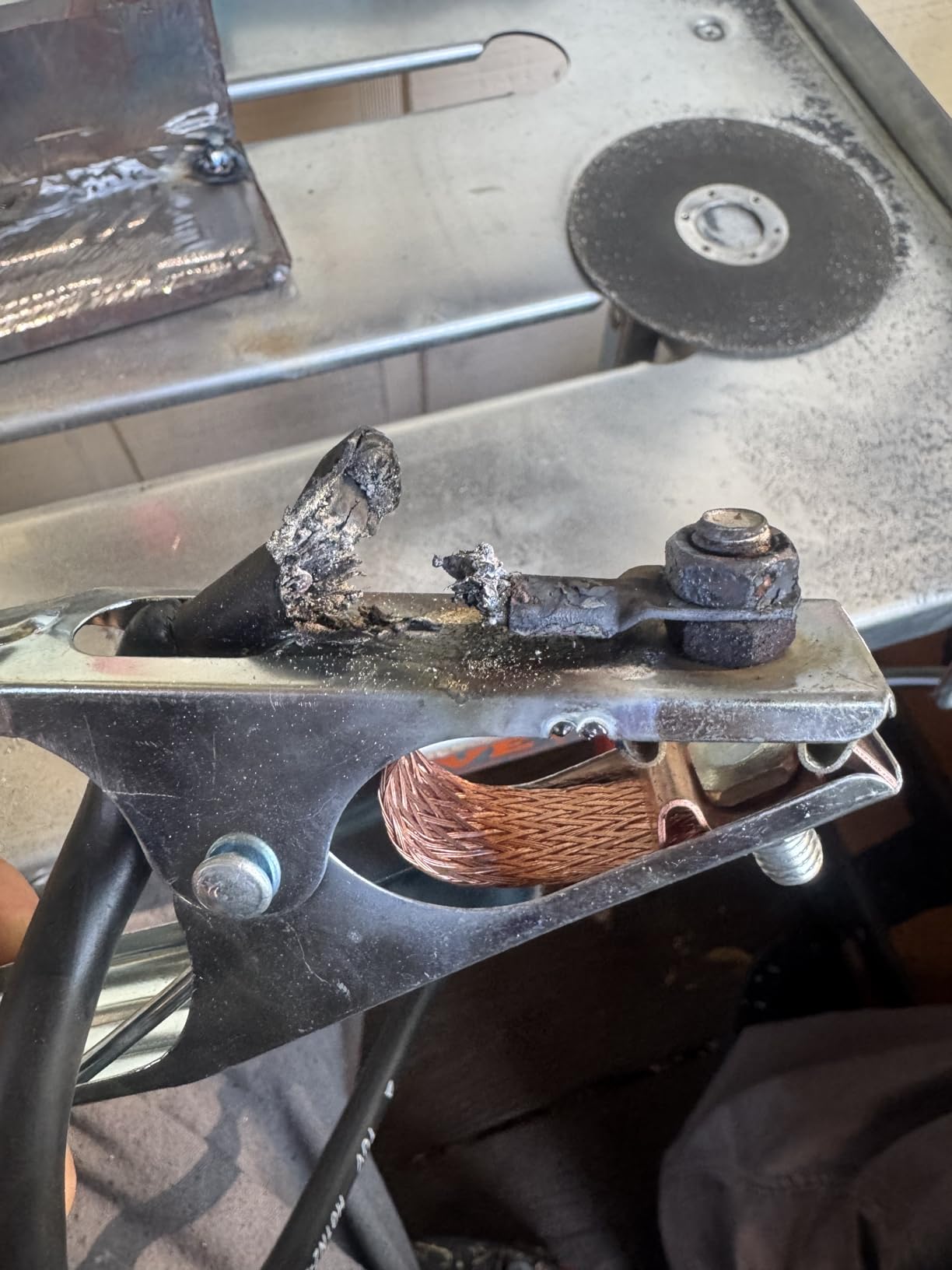
    YESWELDER 205A Tig Welder with Pulse Large LED Display, STICK/DC TIG/PULSE TIG 3 In 1, 110&220V Dual Voltage TIG Welding Machine TIG-205P - Customer Photo 1
    Customer submitted photo

    The dual voltage capability lets you weld on 110V for thinner materials and 220V when you need full power. This flexibility proved invaluable when I brought it to a job site with only standard outlets available.

    High-frequency start eliminates the scratch-start technique that can contaminate tungsten. For copper work, clean arc starts are essential since tungsten contamination shows up clearly in the finished weld.

    View on Amazon We earn from qualifying purchases, at no additional cost to you.

    YESWELDER MIG-205DS PRO – Most Versatile Multi-Process

    MOST VERSATILE
    Product

    YESWELDER 205A MIG Welder, 110V/220V 5-In-1 MIG/Flux Core MIG/Spool Gun MIG/Lift TIG/Stick

    ★★★★★★★★★★4.5 / 5

    Output: 200A

    Processes: 5-in-1 MIG/Flux/TIG/Stick

    Voltage: 110/220V dual

    Features: Synergic mode,Spool gun ready

    Display: Digital

    Check Price

    + Pros

    • 5-in-1 process capability
    • Synergic mode for beginners
    • Spool gun compatible
    • Digital current display
    • Excellent customer support

    Cons

    • Ground clamp quality basic
    • Wire feeder positioning awkward
    • Power cord warms at max output
    • Stick holder feels basic
    We earn from qualifying purchases, at no additional cost to you.

    The MIG-205DS PRO handles copper welding across multiple processes. I’ve used it for MIG welding copper busbars, TIG welding sheet, and even stick welding on repairs—all from the same machine.

    What impresses me most is the synergic mode. It automatically matches voltage to wire speed, making copper MIG welding much more predictable for operators still mastering the process.
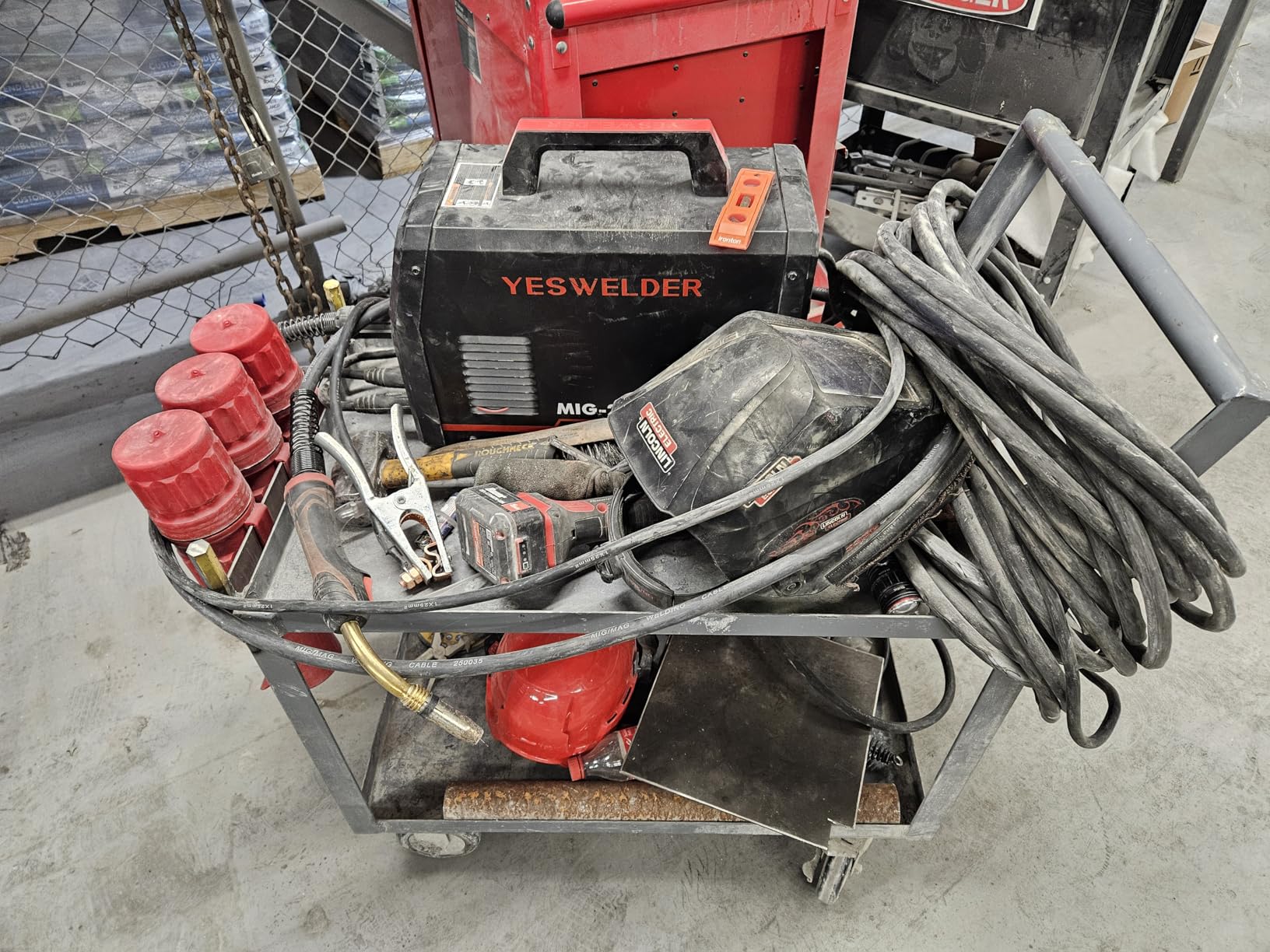
    YESWELDER MIG-205DS PRO MIG Welder, 200Amp 110/220V Dual Voltage MIG Welding Machine, 5 in 1 Gas MIG/Flux Core MIG/Spool Gun MIG/Lift TIG/Stick Multiprocess Aluminum MIG Welder, Spool Gun Compatible - Customer Photo 1
    Customer submitted photo

    The 200-amp output provides sufficient power for copper up to about 3/8-inch with proper preheating. Beyond that thickness, you’re better off with a dedicated industrial machine, but this covers the vast majority of fabrication work.

    Spool gun compatibility means you can weld aluminum too, making this a truly versatile shop machine. The synergic settings reduce the learning curve significantly.

    Customer images demonstrate the machine’s build quality and show real-world welds that users have produced. The digital display provides clear visibility of your settings, which is crucial when dialing in copper welding parameters.
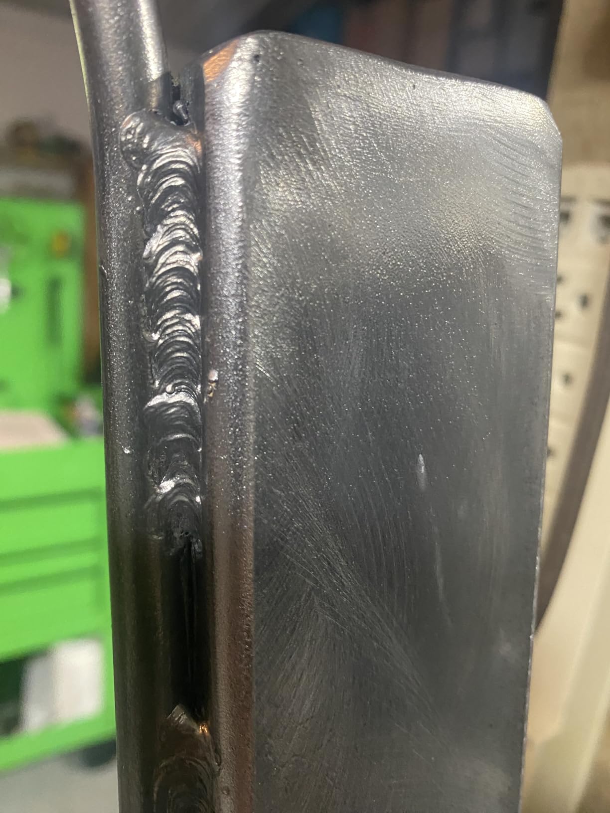
    YESWELDER MIG-205DS PRO MIG Welder, 200Amp 110/220V Dual Voltage MIG Welding Machine, 5 in 1 Gas MIG/Flux Core MIG/Spool Gun MIG/Lift TIG/Stick Multiprocess Aluminum MIG Welder, Spool Gun Compatible - Customer Photo 3
    Customer submitted photo

    I’ve run this unit on both 110V and 220V power. While 110V limits maximum output, it works surprisingly well for thinner copper materials. For production work on thicker material, the 220V connection provides consistent power delivery.

    View on Amazon We earn from qualifying purchases, at no additional cost to you.

    exablo Phosphor Copper Brazing Rods – Self-Fluxing HVAC Solution

    HVAC SPECIALIST

    ★★★★★★★★★★5.0 / 5

    Material: BCuP-2 phosphor copper

    Quantity: 20 rods

    Size: 1/10 inch x 19.6 inches

    Melting point: 1310-1508°F

    Features: Self-fluxing design

    Check Price

    + Pros

    • No flux required-phosphorus acts as flux
    • Low melting point easy flow
    • High tensile strength 130 N/mm
    • Moisture-resistant packaging
    • Eco-friendly materials

    Cons

    • Very limited review data
    • New product with minimal feedback
    • Requires proper technique for best results
    We earn from qualifying purchases, at no additional cost to you.

    These phosphor copper brazing rods simplify HVAC and refrigeration work significantly. The self-fluxing design means no separate flux application is required—the phosphorus content handles that automatically.

    I appreciate the low melting point of 710-820°C, which allows working on copper tubing without overheating surrounding components. This proves especially valuable when working near sensitive connections or valves.

    The 2.5mm diameter feeds smoothly and provides adequate filler material for typical copper pipe joints. Each 19.6-inch rod gives you plenty of material for multiple repairs.

    While review data is limited due to the product’s newness, the specifications align with industry standards for BCuP-2 brazing alloys. The moisture-resistant PVC packaging helps maintain rod quality over time.

    For HVAC technicians and DIYers working on refrigeration systems, these rods offer a convenient solution. The tensile strength of 130 N/mm² ensures joints can handle typical system pressures when properly executed.

    View on Amazon We earn from qualifying purchases, at no additional cost to you.

    SÜA ERCuSi-A Silicon Bronze – Best TIG Brazing Filler

    TOP TIG FILLER
    Product

    SÜA – ERCuSi-A Silicon Bronze TIG Welding Rod – 36'' x 0.045''- (1 Lb)

    ★★★★★★★★★★4.7 / 5

    Material: ERCuSi-A silicon bronze

    Diameter: 0.045 inch

    Length: 36 inches

    Quantity: 1 pound

    Melting point: 1866°F

    Check Price

    + Pros

    • High strength 51000 psi
    • Excellent corrosion resistance
    • Beautiful bronze finish
    • Versatile for multiple metals
    • Good TIG brazing characteristics

    Cons

    • 0.045 diameter feeds quickly
    • Requires heat control practice
    • Not Prime eligible shipping
    We earn from qualifying purchases, at no additional cost to you.

    SÜA’s ERCuSi-A silicon bronze rod produces some of the most attractive copper welds I’ve seen. The 3% silicon content creates excellent wetting action and results in that distinctive bronze finish many fabricators prefer.

    With a tensile strength of 51,000 psi, this filler creates structurally sound joints. I’ve used it extensively for joining copper to steel, where the color transition looks intentional rather than like a repair.
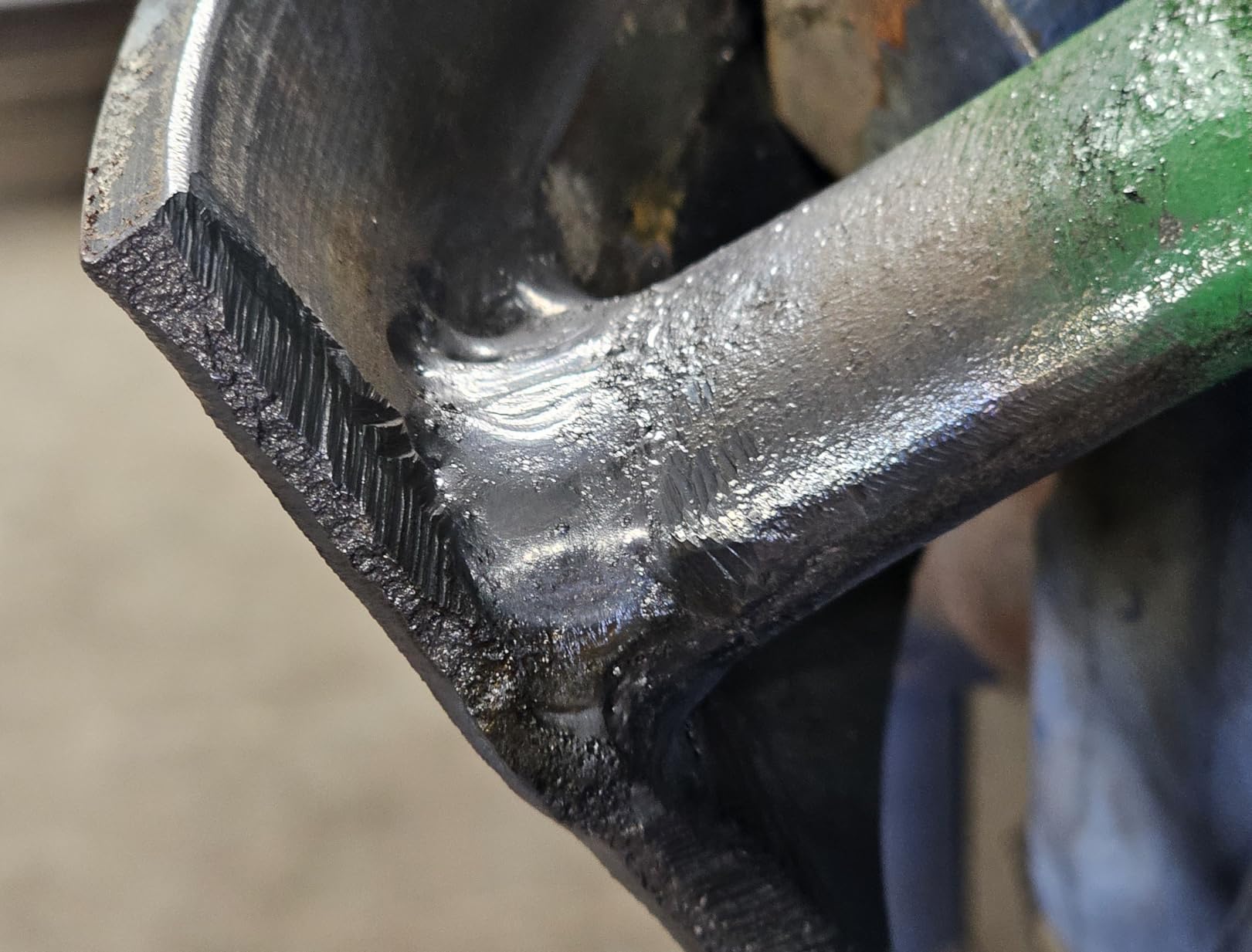
    SÜA - ERCuSi-A Silicon Bronze TIG Welding Rod - 36'' x 0.045''- (1 Lb) - Customer Photo 1
    Customer submitted photo

    The 0.045-inch diameter works well for most TIG applications. It’s fine enough for precision work but substantial enough to deposit filler without feeding frantically. For heavier work, stepping up to 1/8-inch diameter would be my recommendation.

    Customer photos show the beautiful bronze coloration that makes this filler popular for decorative work. The as-welded Brinell hardness of 80-100 indicates good machinability if needed.

    The melting temperature of 1866°F means you need proper amperage control, but the resulting weld beads flow nicely when parameters are correct. I’ve found this filler particularly forgiving for intermediate TIG operators.

    View on Amazon We earn from qualifying purchases, at no additional cost to you.

    COLIBROX 80 cu/ft Argon Cylinder – Complete Shielding Gas Solution

    BEST GAS VALUE
    Product

    80 cu/ft 100% Argon Cylinder Tank Welding Gas CGA 580 – FULL

    ★★★★★★★★★★4.7 / 5

    Capacity: 80 cubic feet

    Gas: 100% Argon

    Connection: CGA 580 valve

    Pressure: 2400 psi fill

    Weight: 50 lbs

    Check Price

    + Pros

    • Higher pressure than typical local fills
    • Convenient home delivery
    • DOT compliant with current dates
    • Ready to use immediately
    • No cylinder exchange hassle

    Cons

    • Non-returnable hazardous material
    • Verify local refill capability first
    • 50 pounds requires care handling
    • Delivery coordination may be needed
    We earn from qualifying purchases, at no additional cost to you.

    Shielding gas quality directly affects copper weld quality, and this 80 cubic foot argon cylinder delivers consistently. The 2400 psi fill exceeds what many local suppliers provide, giving you more welding time between exchanges.

    I recommend pure argon for most copper welding applications. The heavier gas provides excellent shielding coverage, and copper doesn’t require the addition of helium or CO2 that steel welding might need.
    80 cu/ft 100% Argon Cylinder Tank Welding Gas CGA 580 - FULL - Customer Photo 2
    Customer submitted photo

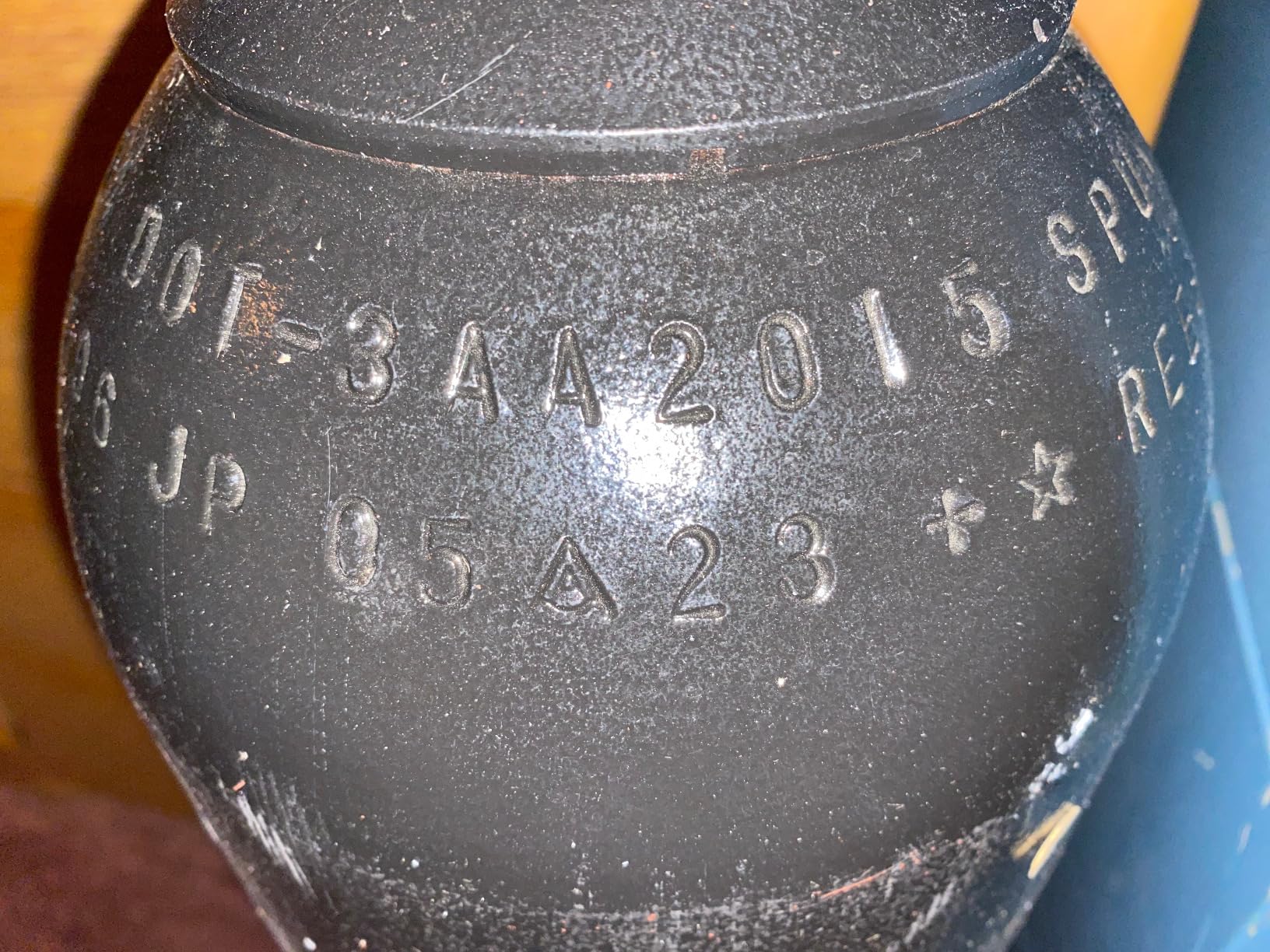
    Before purchasing any cylinder, verify your local gas supplier can fill or exchange it. This cylinder uses the standard CGA 580 valve found on most argon cylinders, so compatibility shouldn’t be an issue at major gas suppliers.

    Customer images confirm the cylinder arrives well-packaged and ready for immediate use. The DOT compliance with current hydrotest dates means you won’t face rejection when getting refills.

    The convenience of home delivery cannot be overstated, especially for rural welders who might drive significant distances to reach a welding supply store. At 50 pounds, plan for assistance moving it into your workspace.
    80 cu/ft 100% Argon Cylinder Tank Welding Gas CGA 580 - FULL - Customer Photo 1
    Customer submitted photo

    This amount of gas provides substantial welding time. For TIG welding copper, I typically run 15-20 CFH, meaning this 80-cubic-foot cylinder delivers approximately 4-5 hours of actual arc time—enough for dozens of copper projects.

    View on Amazon We earn from qualifying purchases, at no additional cost to you.

    MAXMAN Wire Brush Set – Best Copper Cleaning Brush
    AMAZON'S CHOICE
    Product

    MAXMAN Wire Brush, Heavy Duty Stainless Steel Wire Brushes for Cleaning Rust, Grill Brush, Steel Brush for Paint Removal, Welding, Stiff Bristle Metal Brush with 10" Long Beech Handle, Large, 2Pcs

    ★★★★★★★★★★4.7 / 5

    Material: Stainless steel bristles

    Handle: 10 inch beech wood

    Quantity: 2 pack

    Bristle rows: 4 x 16

    Features: Ergonomic curved design

    Check Price

    + Pros

    • Stiff bristles remove oxidation effectively
    • Long handle keeps hands clear
    • Ergonomic comfortable grip
    • Excellent value 2-pack
    • Versatile for multiple uses

    Cons

    • Can scratch if not used carefully
    • Stainless steel may rust if not dried
    • Not for delicate surfaces
    We earn from qualifying purchases, at no additional cost to you.

    Proper copper cleaning requires dedicated brushes, and this MAXMAN set delivers excellent performance. The stainless steel bristles remove oxidation effectively without loading up like carbon steel brushes do.

    The 10-inch beech wood handle provides excellent leverage and keeps your hands away from the work surface. I’ve found this especially valuable when cleaning larger copper sheets before welding.
    MAXMAN Wire Brush, Heavy Duty Stainless Steel Wire Brushes for Cleaning Rust, Grill Brush, Steel Brush for Paint Removal, Welding, Stiff Bristle Metal Brush with 10
    Customer submitted photo

    Two brushes in the pack means you can designate one solely for copper work, preventing cross-contamination with ferrous metals. Steel particles embedded in copper create rust spots and weaken the weld.

    Customer photos show the brush construction and real-world use on various metals. The 4 x 16 bristle configuration provides aggressive cleaning action while the curved handle fits naturally in your hand.

    The stiff bristles work particularly well on oxidized copper surfaces. I’ve used these brushes extensively for pre-weld cleaning and found they maintain their stiffness better than cheaper alternatives.
    MAXMAN Wire Brush, Heavy Duty Stainless Steel Wire Brushes for Cleaning Rust, Grill Brush, Steel Brush for Paint Removal, Welding, Stiff Bristle Metal Brush with 10
    Customer submitted photo

    For copper sheet preparation, I recommend brushing in the direction of the intended weld. This technique helps align any surface contaminants and makes the final cleaning with solvent more effective.

    View on Amazon We earn from qualifying purchases, at no additional cost to you.

    YESWELDER Auto Darkening Helmet – #1 Best Seller Protection

    #1 BEST SELLER
    Product

    YESWELDER Auto Darkening Welding Helmet 1/1/1/1 True Color, LYG-L600A

    ★★★★★★★★★★4.6 / 5

    Shade range: 3.5/9-13

    Optical clarity: 1/1/1/1

    Response time: 1/30000 sec

    Sensors: 2 arc sensors

    Power: Solar + battery

    Check Price

    + Pros

    • Excellent 1/1/1/1 optical clarity
    • Blue light blocking technology
    • Lightweight 1 pound design
    • Fast auto-darkening response
    • Solar power with battery backup

    Cons

    • Head strap may slip during movement
    • Battery occasionally factory installed wrong
    • Viewing area smaller than panoramic models
    We earn from qualifying purchases, at no additional cost to you.

    This helmet dominates the welding helmet market for good reason. The 1/1/1/1 optical clarity rating indicates top-tier performance across all optical quality metrics, which significantly reduces eye strain during long welding sessions.

    Copper welding produces intense visible light and UV radiation. The blue light blocking technology in this YESWELDER helmet provides additional protection that standard helmets might miss.
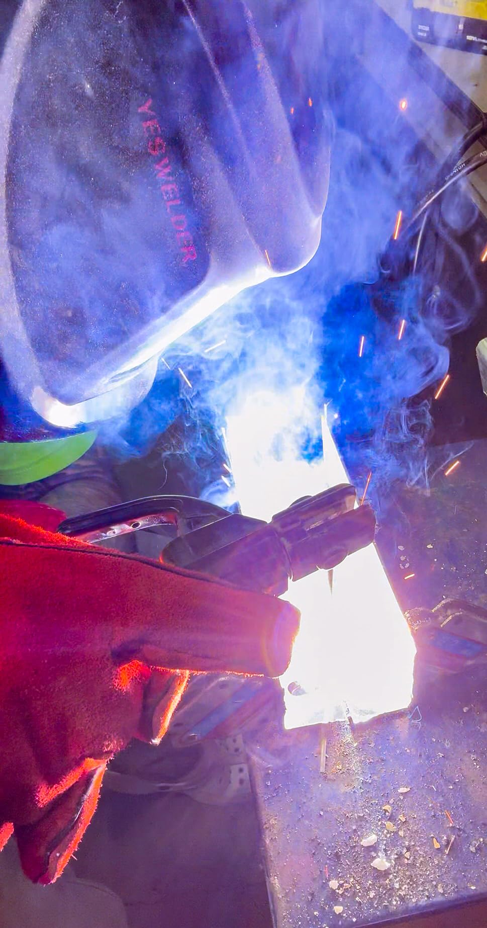
    YESWELDER Auto Darkening Welding Helmet, Blue Light Blocking, 1/1/1/1 True Color Solar Powered Welding Hood with 2 Arc Sensors, Wide Shade 3.5/9-13 Welder Mask for TIG MIG ARC and Grind - Customer Photo 2
    Customer submitted photo

    The 1/30000 second response time is practically instantaneous. This fast switching protects your eyes from flash and allows you to see your weld pool clearly immediately after striking an arc—critical for copper TIG work where precision matters.

    Customer images show the helmet in real-world use and confirm the viewing area dimensions. At 3.64 x 1.67 inches, the viewing area provides adequate workspace visibility while keeping the helmet lightweight.

    At only 1 pound, this helmet reduces neck fatigue during extended welding sessions. I’ve worn it for 4+ hours of copper fabrication work without the discomfort that heavier helmets cause.
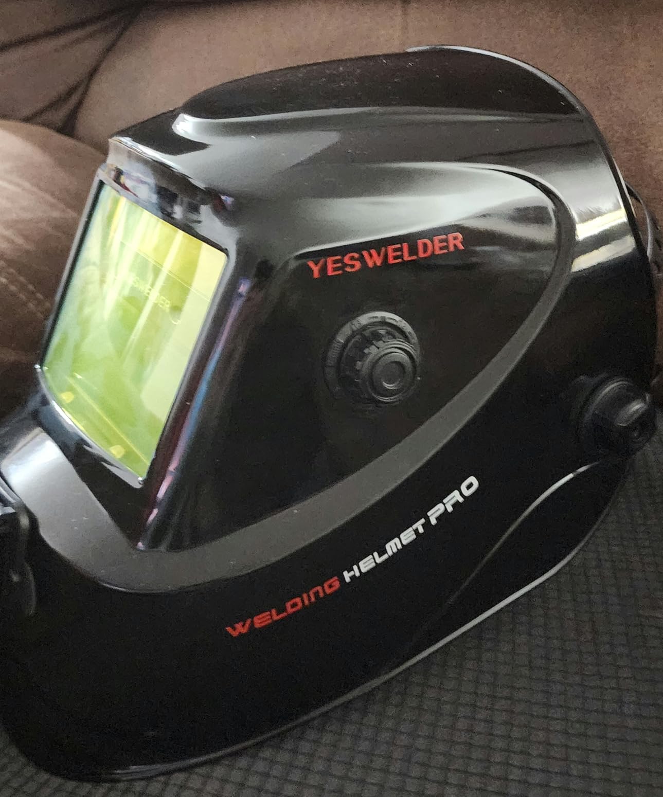
    YESWELDER Auto Darkening Welding Helmet, Blue Light Blocking, 1/1/1/1 True Color Solar Powered Welding Hood with 2 Arc Sensors, Wide Shade 3.5/9-13 Welder Mask for TIG MIG ARC and Grind - Customer Photo 1
    Customer submitted photo

    The wide shade range of 3.5/9-13 accommodates all copper welding processes. I typically use shade 11-12 for TIG welding copper, stepping up to 13 for heavier MIG work. The shade 3.5 light state is bright enough to see your work clearly without lifting the helmet.

    View on Amazon We earn from qualifying purchases, at no additional cost to you.

    TOPDC Welding Gloves – Heat Resistant Protection

    #2 BEST SELLER
    Product

    TOPDC Welding Gloves 16-Inch 932°F Heat Resistant Leather for MIG, Stick

    ★★★★★★★★★★4.6 / 5

    Length: 16 inches

    Heat resistance: 932°F (500°C)

    Material: 1.2mm cowhide leather

    Lining: 100% cotton

    Features: Kevlar stitched

    Check Price

    + Pros

    • Extreme heat resistance
    • 16 inch sleeve protects forearm
    • Soft leather allows dexterity
    • Kevlar stitching adds durability
    • Cotton lining comfortable

    Cons

    • May run large for some users
    • Not machine washable
    • Contact heat resistance limited to 15 seconds
    We earn from qualifying purchases, at no additional cost to you.

    Copper welding involves significant heat exposure, and these 16-inch gloves provide comprehensive protection. The 932°F heat resistance rating covers most copper welding applications when proper technique is used.

    The extra length extends protection well up your forearm, which I’ve found invaluable when TIG welding copper. The heat from larger copper pieces radiates further than you expect, and full forearm coverage prevents burns.
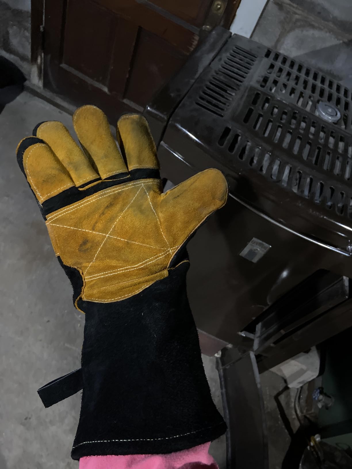
    TOPDC Welding Gloves 16 Inches 932℉ Fire/Heat Resistant Leather Welding Gloves For Mig, Tig, Stick, Forge, BBQ, Grill, Fireplace, Wood Stove, Furnace, Oven, Animal Handling - Customer Photo 1
    Customer submitted photo

    What surprises me about these gloves is the dexterity they maintain despite the 1.2mm leather thickness. I can manipulate TIG torches and filler rods with reasonable precision, something impossible with cheaper, stiffer gloves.

    Customer images demonstrate the glove quality and show real-world use in various applications. The Kevlar stitching throughout adds significant durability—stitching failure is what dooms most welding gloves, and TOPDC addressed this weakness directly.

    The 100% cotton lining makes these gloves comfortable for extended wear. I’ve worn them through hours of copper fabrication without the excessive sweating that synthetic linings cause.
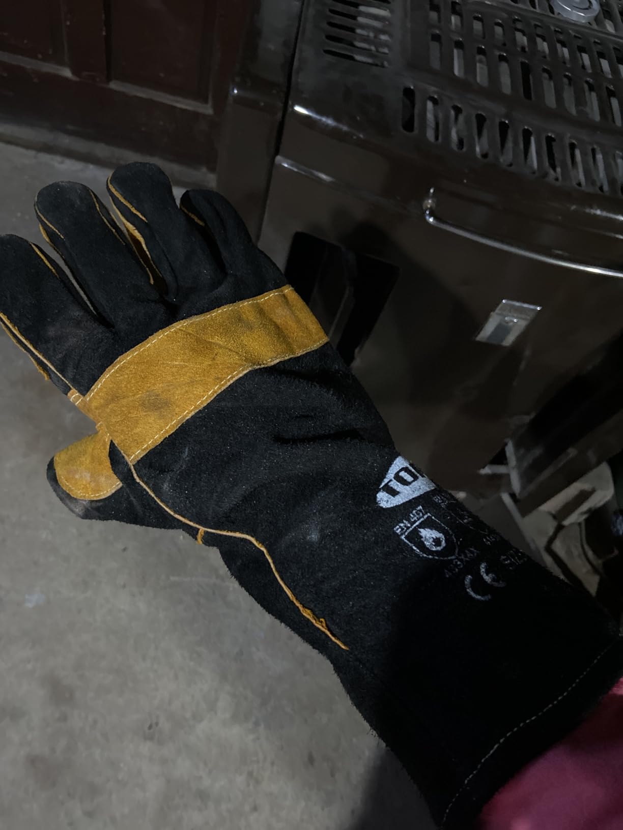
    TOPDC Welding Gloves 16 Inches 932℉ Fire/Heat Resistant Leather Welding Gloves For Mig, Tig, Stick, Forge, BBQ, Grill, Fireplace, Wood Stove, Furnace, Oven, Animal Handling - Customer Photo 2
    Customer submitted photo

    Double leather sewing on stress points reinforces the areas that typically fail first. After months of use, my pair shows minimal wear despite daily exposure to high heat and abrasion.

    While rated for welding, these gloves serve double duty in my shop for handling hot copper pieces after welding. The 16-inch length lets me grab hot workpieces from the table without risking arm burns.

    View on Amazon We earn from qualifying purchases, at no additional cost to you.

    Common Problems and Solutions

    Even with proper preparation, copper welding presents unique challenges. I’ve encountered and solved most common issues through trial and error.

    Porosity in Copper Welds

    Porosity remains the most common copper welding defect I see. Those small gas pockets weaken welds and create leak paths in pressure-critical applications.

    The primary causes I’ve identified include:

    • Insufficient cleaning before welding
    • Moisture in filler material or base metal
    • Incorrect gas flow rate (too low or too high)
    • Shielding gas contamination

    Solutions that work for me include extending cleaning time, storing filler rods in climate-controlled areas, and verifying gas flow with a flowmeter rather than relying on regulator gauges.

    Cracking in Heat-Affected Zone

    Cracking typically occurs from excessive restraint combined with rapid cooling. Copper’s high thermal expansion means joints move significantly as they heat and cool.

    I prevent cracking by:

    • Using proper joint designs with some flexibility
    • Preheating to reduce thermal gradients
    • Allowing controlled cooling (not quenching)
    • Peening welds while still slightly warm

    Lack of Fusion

    When copper doesn’t fuse properly, it’s usually from insufficient heat input or poor technique. Copper’s high thermal conductivity means heat dissipates rapidly.

    Solutions include increasing amperage, improving preheating, and ensuring proper torch angle. For TIG welding, I aim the arc more directly into the joint rather than riding the surface.

    Warping and Distortion

    Copper warps more than steel during welding due to higher thermal expansion. I control distortion through:

    • Clamping workpieces securely but with some allowance for movement
    • Using intermittent weld sequences rather than continuous welds
    • Planning weld sequence to balance shrinkage forces
    • Pre-setting joints to compensate for expected movement

    Safety Considerations

    Copper welding requires specific safety precautions beyond standard welding practices. I’ve learned that copper presents unique hazards that deserve respect.

    Ventilation Requirements

    Copper welding fumes contain metal particulates that can cause respiratory issues. Adequate ventilation is non-negotiable in my shop.

    I use a combination of general shop ventilation plus local exhaust at the welding point. For frequent copper welding, a fume extractor rated for metal particulates is worth the investment.

    Copper Toxicity Concerns

    While copper itself isn’t highly toxic, copper alloys containing zinc (like brass) produce zinc oxide fumes when welded. These fumes cause metal fume fever if inhaled in sufficient quantities.

    Know what alloy you’re welding and adjust your ventilation accordingly. Pure copper produces fewer hazardous fumes than copper-zinc alloys.

    Personal Protective Equipment

    Quality PPE is essential for copper welding. I never weld without:

    • Auto-darkening helmet with proper shade rating
    • Respirator rated for metal particulates when ventilation is questionable
    • Leather welding gloves with forearm protection
    • Natural fiber clothing (synthetics melt and stick to skin)
    • Closed-toe leather boots

    The investment in quality protective equipment pays dividends in long-term health. I’ve seen too many welders develop respiratory issues from inadequate protection.

    Frequently Asked Questions

    What is the best welding process for copper?

    TIG welding produces the highest quality copper welds for most applications. It offers precise heat control essential for copper’s high thermal conductivity. MIG welding works well for thicker copper sections where speed matters. For thin copper sheet under 1/8 inch, TIG is unmatched in control and finish quality.

    What gas do you use for welding copper?

    Pure argon is the standard shielding gas for most copper welding applications. It provides excellent arc stability and prevents oxidation during welding. For thicker copper sections over 1/4 inch, adding helium to the argon increases heat input. A 75/25 argon-helium mixture is common for heavy copper welding.

    Do you need to preheat copper before welding?

    Yes, preheating copper is essential for thickness over 1/8 inch. Copper’s high thermal conductivity dissipates heat rapidly, making fusion difficult without preheating. Typical preheat temperatures range from 300-500F for medium thickness and up to 1200F for thick sections. Always preheat uniformly across the workpiece for best results.

    What filler rod for copper welding?

    ERCuSi-A silicon bronze is the most versatile filler for copper welding. It offers excellent flow, strength, and corrosion resistance. For color matching in electrical applications, ERCu deoxidized copper works best. Phosphor bronze (BCuP) excels for HVAC and refrigeration work due to self-fluxing properties.

    Can you stick weld copper?

    Stick welding copper is possible but challenging. I recommend it only for field repairs or when other equipment is unavailable. Specialized bronze rods designed for copper work provide the best results. The process requires higher skill than TIG or MIG due to copper’s rapid heat dissipation fighting against the stick arc.

    Is welding copper toxic?

    Pure copper welding produces relatively low toxicity fumes compared to other metals. However, adequate ventilation remains essential. Copper alloys containing zinc produce zinc oxide fumes that can cause metal fume fever. Always use proper ventilation and respiratory protection when welding any copper material. Know your specific alloy’s composition before welding.

    Copper welding rewards patience and proper preparation. After years of practice, I’ve found that respecting copper’s unique properties rather than fighting against them produces the best results. Start with clean material, appropriate preheating, and the right process for your application. The skills you develop working with copper transfer well to all types of welding, making it an excellent teacher for metal fabrication fundamentals.
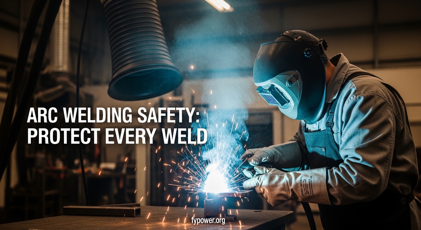
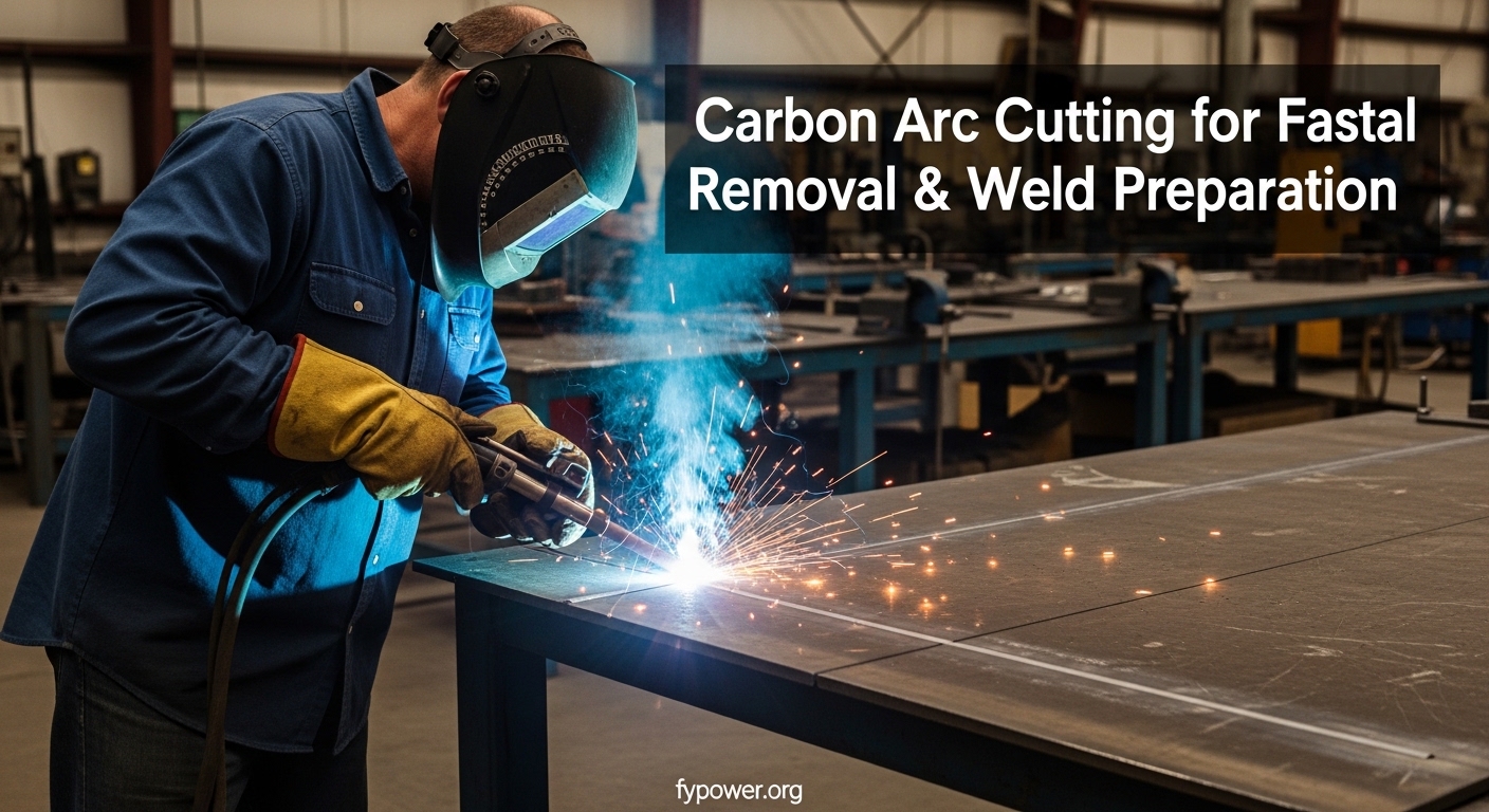
  • Arc Welding Safety Checklist for Welders 2026

    Arc Welding Safety Checklist for Welders 2026

    I still remember the day my welding instructor told our class about a local fabricator who spent three days in the hospital because he skipped his helmet for “just one tack weld.” That single mistake cost him $12,000 in medical bills and two months of lost work. After 10 years in metal fabrication, I’ve seen welders make every safety mistake in the book. Some learned the hard way. Others got lucky.

    Arc welding creates temperatures up to 6,500 degrees Fahrenheit and generates invisible UV radiation that can damage your eyes in less than a second. The arc flash is brighter than the sun, and the fumes contain metal particles that accumulate in your lungs over years of exposure. I’ve worked in production shops, custom fabrication, and my own home garage. The safety principles never change, but I see beginners skip them constantly.

    Arc welding safety requires comprehensive protection: proper PPE including a helmet with correct shade lenses, fire-resistant clothing, leather gloves, and steel-toed boots; adequate ventilation or respiratory protection; electrical safety through proper grounding and dry conditions; fire prevention with a 35-foot clearance from flammables; and following OHA standards 1910.254 and ANSI Z49.1.

    Quick Summary: Arc welding generates five primary hazards: electric shock, UV/IR radiation, welding fumes, fire, and burns. Full protection requires rated PPE, proper ventilation, grounded equipment in dry conditions, fire extinguisher access, and following established safety procedures every single weld.

    The 5 Critical Arc Welding Hazards Explained

    Understanding these hazards is the first step toward protecting yourself. Let me break down each one based on what I’ve seen in real workshops.

    Electric Shock: The Silent Killer

    The welding output circuit ranges from 20 to 80 volts in open-circuit conditions. That might not sound like much compared to household outlets, but it becomes extremely dangerous when your skin is wet or you’re touching grounded metal. The primary shock hazard comes from the output circuit, not the input power.

    I knew a welder who got knocked across the room when his sweaty forearm touched the workpiece while changing electrodes. He was lucky. Another fabricator in my city wasn’t—he died from a similar incident. Secondary voltage shock kills an estimated 50 workers annually in the United States.

    Never touch live electrical parts with bare skin. Keep your gloves dry. Inspect cables for exposed conductors before every use. Use insulation mats when welding on or near grounded surfaces. And never work in wet conditions—water drastically reduces your body’s resistance to electrical current.

    UV Radiation and Arc Eye

    The welding arc produces intense ultraviolet radiation that causes photokeratitis—commonly called arc eye or welder’s flash. It’s essentially a sunburn on your corneas. I’ve experienced it twice. Both times, I woke up at 2 AM feeling like someone poured sand in my eyes.

    Symptoms appear 6-12 hours after exposure. Your eyes become extremely sensitive to light, tear uncontrollably, and feel like they’re full of grit. The condition is temporary but miserable. Repeated exposure can cause cataracts and permanent vision damage.

    UV radiation also damages exposed skin. I’ve seen welders with what looks like a severe sunburn after just 15 minutes of welding without proper coverage. Long-term, this causes premature aging and increases skin cancer risk.

    Arc Eye (Photokeratitis): A painful eye condition caused by unprotected exposure to UV radiation from welding arcs. Symptoms include severe eye pain, light sensitivity, excessive tearing, and the sensation of foreign objects in the eyes. Symptoms typically appear 6-12 hours after exposure.

    Welding Fumes and Long-Term Health

    Welding fumes contain a complex mixture of metal oxides, gases, and particulates. The exact composition depends on the base metal, filler material, and any coatings present. Common components include manganese, chromium, nickel, and zinc.

    Manganese exposure is particularly concerning. Long-term inhalation can cause manganism—a neurological condition similar to Parkinson’s disease. I’ve worked with older welders who developed hand tremors and slow movement after decades of welding without respiratory protection.

    Zinc fumes from galvanized steel cause metal fume fever—flu-like symptoms that appear 4-12 hours after exposure. I’ve had it once. Fever, chills, nausea, and muscle aches kept me in bed for 24 hours. It’s temporary but miserable, and repeated episodes indicate overexposure.

    Fire and Explosion Risks

    Every welding operation throws sparks—sometimes up to 35 feet from the work area. These sparks can reach 2,500 degrees Fahrenheit and stay hot enough to ignite materials for considerable distances. I’ve seen sparks land in sawdust, through floor cracks, and on rags sitting 20 feet away.

    Explosions are an even greater threat. Welding on containers that previously held flammable materials has killed countless workers. The heat from welding can vaporize residual flammable substances inside closed containers. The vapor expands, pressure builds, and—boom.

    I personally investigate every container before welding. I look for labels, smell for odors, and test with electronic gas detectors when available. When in doubt, I fill the container with water or inert gas before welding. There’s no project worth dying for.

    Burn Hazards

    Molten metal, hot slag, and heated workpieces cause immediate and severe burns. The weld pool stays liquid at 2,500-3,000 degrees. Slag can remain hot enough to burn through leather boots an hour after welding.

    I have burn scars on both forearms from early in my career. One happened when I rested my arm on a piece I’d welded 20 minutes earlier. Another came from slag that dropped inside my boot cuff. These injuries were painful and preventable with proper positioning and full coverage clothing.

    Personal Protective Equipment (PPE): Complete Guide

    Proper PPE is your last line of defense. When engineering controls and safe work practices fail—which they will at some point—your gear is what stands between you and injury. Let me walk through each piece of essential equipment.

    Head and Face Protection

    The welding helmet is your most critical piece of PPE. It protects your face from sparks and spatter, your eyes from UV radiation, and provides shade to see the weld pool clearly. I’ve used everything from $30 fixed-shade helmets to $600 auto-darkening models.

    Auto-darkening helmets have transformed the industry. Instead of flipping your helmet up and down constantly, the lens darkens automatically when you strike an arc. This reduces neck strain and improves precision. Good models react in 1/20,000 of a second—fast enough to prevent flash.

    Shade selection is critical. Too light and your eyes strain. Too dark and you can’t see the workpiece. Here’s what I use for different processes:

    Welding ProcessAmperage RangeRecommended Shade
    Stick (SMAW)Under 60AShade 7-8
    Stick (SMAW)60-160AShade 10
    Stick (SMAW)160-250AShade 12
    MIG (GMAW)60-160AShade 10
    MIG (GMAW)160-300AShade 12-13
    TIG (GTAW)Under 50AShade 8-9
    TIG (GTAW)50-150AShade 10-11
    Carbon Arc GougingAll amperagesShade 14

    Safety glasses are mandatory underneath your helmet. Sparks can bounce off your workpiece and find their way behind your helmet. I’ve had it happen. Now I always wear ANSI Z87.1-rated side-shield glasses. Clear polycarbonate lenses work for most applications.

    Hand and Arm Protection

    Welding gloves aren’t one-size-fits-all. Different processes require different gloves. I keep three types in my shop:

    Glove TypeBest ForKey Features
    Stick/MIG GlovesHeavy-duty weldingThick leather, elbow-length, lined
    TIG GlovesPrecision TIG weldingThin, supple, finger dexterity
    Driver GlovesMaterial handlingMedium weight, good grip

    For Stick and MIG welding, I use heavy Elkskin or cowhide gloves that extend past my elbows. The extra length protects my forearms from radiant heat and UV radiation. These gloves are thick enough that I can’t feel small parts—I switch to lighter gloves for grinding and material handling.

    TIG welding requires much more finger dexterity. I use thin goatskin or pigskin gloves that allow me to feel the torch and filler rod. They sacrifice some heat protection, but I can’t TIG weld effectively in thick gloves.

    Body Protection

    Your clothing creates a barrier against sparks, UV radiation, and burns. I’ve seen welders wear cotton t-shirts and wonder why they end up with sunburned arms. Synthetic materials are even worse—they melt into your skin when hit by sparks.

    Wear natural fibers only. Cotton is acceptable for light work. Wool is better because it’s naturally flame-resistant and provides some insulation. For serious production work, invest in fire-resistant clothing treated with flame-retardant chemicals.

    A welding jacket or cape is your best upper-body protection. Jackets cover your torso, arms, and neck. Capes cover your upper body but leave your arms free—great for TIG welding where you need mobility. I prefer jackets for Stick and MIG work.

    Welding aprons protect your torso and thighs from spatter while leaving your arms free. They’re lighter than jackets and work well for bench work. I use one when doing lots of tack welding or position work where mobility matters.

    Pants should cover your boots completely. Cuffs can catch sparks and let them fall inside your boots. I’ve seen this happen—it’s not fun. Heavy denim or canvas works well. For production welding, fire-resistant coveralls provide the best protection.

    Foot Protection

    Leather boots with steel toes are mandatory. Sparks will burn through athletic shoes in seconds. I’ve seen the aftermath—a welder spent three weeks recovering from severe foot burns because he wore sneakers “just for a quick weld.”

    High-topped boots provide ankle protection and prevent sparks from entering the top. Metatarsal guards add protection for the top of your foot—essential when doing overhead work or heavy fabrication where falling slag is common.

    Electrical hazard-rated boots add insulation against electrical shock. They’re worth the extra cost if you weld in damp conditions or work on grounded surfaces frequently.

    Hearing Protection

    Arc welding generates 85-100 decibels of noise. Grinding and cutting push that well over 100 dB. Repeated exposure causes permanent, irreversible hearing damage. I have mild tinnitus from my early years of welding without ear protection.

    Use earplugs for welding alone. Add earmuffs when grinding or cutting. Combined protection provides better noise reduction. Electronic earmuffs amplify quiet sounds while blocking loud noise—great for workshop environments where you need to hear instructions.

    Electrical Safety: Preventing Shock Hazards

    Electrical safety deserves your complete attention. The welding machine produces lethal current under the right conditions. I’ve been shocked twice—both times because I got careless. Learn from my mistakes.

    Proper Grounding Procedures

    The workpiece must be properly connected to the welding machine’s work terminal. This is called the work lead or ground clamp. A poor connection causes the welding current to find alternate paths—possibly through you.

    I always connect my ground clamp to clean, bare metal. Paint, rust, and coatings are insulators. If the clamp won’t bite into the material, I grind or wire brush the contact area. For large assemblies, I connect multiple ground clamps to ensure good conductivity throughout.

    Never ground to structures that might carry current unexpectedly. I once saw a welder ground to a pipe that ran to another building. Unknown to him, that pipe was bonded to electrical conduit elsewhere. When he struck an arc, the current found multiple paths and created a shock hazard throughout both buildings.

    Working in Wet Conditions

    Water and electricity don’t mix. This is non-negotiable. Never weld in rain, standing water, or wet conditions. If you must weld outdoors in damp weather, take these precautions:

    1. Use dry rubber mats or wooden platforms to stand on
    2. Keep all electrical connections elevated and dry
    3. Wear dry rubber gloves underneath your welding gloves
    4. Use a ground fault circuit interrupter (GFCI) if available
    5. Consider postponing the work until conditions improve

    Sweat is also conductive. In hot weather, I keep a rag handy to wipe my hands and arms before touching electrical connections. I change gloves when they become soaked through.

    Equipment Inspection

    Inspect your welding equipment before every use. Damaged insulation, exposed conductors, and worn connections are shock hazards waiting to happen. I spend two minutes checking my cables before every welding session. Those two minutes have prevented at least three potential shocks over the years.

    Check for:

    • Cracks or cuts in cable insulation
    • Exposed conductors at connection points
    • Damage to electrode holders or torches
    • Loose or corroded connections
    • Worn trigger switches on MIG guns and TIG torches

    Replace damaged equipment immediately. Don’t tape over cut cables—that’s a temporary fix at best and a false sense of security at worst.

    Ventilation and Respiratory Protection

    Welding fumes are insidious. You can’t see most of them, and you often don’t notice the effects until years of exposure have accumulated. I take respiratory protection seriously—my lungs have to last me the rest of my life.

    Natural Ventilation

    Natural ventilation works for light welding in open areas. Open doors and windows on opposite sides of your workspace to create cross-ventilation. Position fans to blow fumes away from your breathing zone—not toward the weld or they’ll interfere with shielding gas.

    For a typical home garage, I recommend at least two sources of intake and exhaust. A 16-foot garage door plus a window on the opposite wall provides decent cross-ventilation for light Stick or MIG welding. This setup is adequate for welding mild steel for short periods.

    Mechanical Ventilation

    For production welding or confined spaces, natural ventilation isn’t enough. You need mechanical solutions:

    Ventilation TypeBest ForAirflow Required
    General ExhaustLarge open shops2,000+ CFM total room air changes
    Local ExhaustFixed welding stations100-150 CFM at capture point
    Portable Fume ExtractorFlexible positioning150-300 CFM adjustable
    Downdraft TableBench welding100-150 CFM through table surface

    Local exhaust ventilation captures fumes at the source—the most effective approach. A flexible arm fume extractor positioned 6-12 inches from the weld zone captures the majority of fumes before they disperse. I use one in my home shop for any welding session longer than 15 minutes.

    Respiratory Protection

    When ventilation isn’t adequate or you’re welding materials that produce toxic fumes, respiratory protection is mandatory. I use respirators for:

    • Stainless steel (contains chromium and nickel)
    • Galvanized steel (zinc fumes)
    • Painted or coated materials
    • Confined spaces
    • Extended welding sessions in any material

    For most welding, a half-face respirator with P100 filters provides adequate protection. These filters capture 99.97% of particles down to 0.3 microns. Replace filters regularly—when breathing becomes difficult or after 40 hours of use, whichever comes first.

    For high-production environments or confined spaces, consider a powered air-purifying respirator (PAPR). These systems use a blower to pull air through filters and deliver it to your helmet. They’re more expensive but much more comfortable for all-day use.

    Metal Fume Fever: A flu-like condition caused by inhaling metal oxide fumes, typically from zinc oxide when welding galvanized steel. Symptoms include fever, chills, nausea, muscle aches, and headache. Symptoms appear 4-12 hours after exposure and typically resolve within 24-48 hours. Repeated episodes indicate excessive exposure.

    Fire Prevention and Hot Work Procedures

    I’ve responded to three welding-related fires in my career. Two were small—one extinguisher handle and done. The third burned through an exterior wall and caused $80,000 in damage. All three were preventable.

    Establishing a Safe Welding Area

    Before you strike an arc, clear the area. This means a 35-foot radius in all directions. Remove or protect anything that can burn. I scan my welding area for:

    • Paper, cardboard, and packaging materials
    • Wood scraps and lumber
    • Oil-soaked rags
    • Gasoline, paints, and solvents
    • Dry leaves and vegetation (for outdoor welding)
    • Floor cracks and openings where sparks can fall

    For flammable materials that can’t be moved, cover them with fire-resistant welding blankets. These are made from fiberglass or silica fabrics that can withstand direct flame. I use them when welding near vehicles, machinery, or building components that can’t be relocated.

    Fire Extinguishers: Essential Equipment

    Keep a fire extinguisher within 10 feet of your welding area. Know how to use it before you need it. The last thing you want to be doing during a fire is reading instructions.

    For welding, I recommend an ABC-rated extinguisher with at least a 10-pound capacity. This classification covers:

    • Class A: Ordinary combustibles (wood, paper, cloth)
    • Class B: Flammable liquids (gasoline, oil, paint)
    • Class C: Electrical fires

    Check your extinguisher monthly. Verify the pressure gauge is in the green zone. Inspect the hose and nozzle for damage. Shake dry chemical extinguishers occasionally to prevent the agent from packing down.

    The Fire Watch: When It’s Required

    A fire watch is a person assigned to monitor for fires during and after hot work. They’re required when:

    • Welding near combustible materials that couldn’t be moved
    • Working in areas with concealed combustible spaces (walls, ceilings)
    • Welding in confined spaces
    • Required by workplace policy or local regulations

    The fire watch continues for at least 30 minutes after welding stops. Many fires start well after the weld is complete because sparks smolder undetected. I’ve seen this happen—a spark landed in cardboard inside a cabinet and smoldered for 45 minutes before bursting into flame.

    Hot Work Permits?

    Commercial and industrial settings often require hot work permits for welding. These documents ensure that:

    • The fire department is notified
    • Flammable materials are removed or protected
    • Fire extinguishers are present
    • A fire watch is assigned
    • Fire detection and suppression systems are functional

    Even in home workshops, I recommend following hot work permit procedures. Treat your home with the same respect as a commercial facility. Your family and neighbors deserve the same protection as industrial workers.

    Safe Work Practices: Your Daily Checklist

    Safety isn’t about what you know—it’s about what you do every single day. I’ve developed a checklist that I run through before every welding session. These habits have kept me safe through thousands of hours of welding.

    Pre-Welding Safety Checklist

    Before you strike an arc, complete these steps:

    1. Inspect your PPE: Check helmet lens for cracks, gloves for holes, boots for damage
    2. Check fire extinguisher: Verify it’s charged and accessible
    3. Clear the area: Remove combustibles within 35 feet
    4. Inspect welding equipment: Check cables, connections, and torch for damage
    5. Verify ground connection: Ensure work lead is securely attached to clean metal
    6. Assess ventilation: Confirm adequate airflow or prepare respirator
    7. Check for fire hazards: Look for openings where sparks could travel
    8. Protect bystanders: Set up welding screens or post warning signs

    During Welding: Stay Alert

    Maintain awareness while you weld. It’s easy to get focused on the weld bead and forget your surroundings. I make a conscious effort to:

    • Monitor where sparks are landing
    • Watch for smoke indicating hidden fires
    • Stay aware of people entering the area
    • Notice if ventilation becomes inadequate
    • Pay attention to physical discomfort or overheating

    Take breaks when needed. Fatigue leads to mistakes. I stop every hour for a few minutes to hydrate and assess my surroundings. In hot weather, I take breaks more frequently. Heat stress is real, and it impairs judgment.

    Post-Welding Procedures

    The job isn’t done when you finish welding. Follow these shutdown procedures:

    1. Turn off welding machine: At the machine, not just the gun trigger
    2. Release gas pressure: For MIG/TIG, close cylinder valve and bleed lines
    3. Inspect the work area: Look for smoldering materials
    4. Check adjacent areas: Sparks travel—look beyond immediate work area
    5. Continue fire watch: Wait 30-60 minutes before leaving unattended
    6. Store equipment properly: Coiled cables, secured cylinders, organized workspace

    Confined Space Welding

    Welding in confined spaces—tanks, vessels, pits, crawl spaces—requires extra precautions. These spaces have limited ventilation and restricted exits. Several welders die annually in confined space incidents.

    Confined Space: An area large enough to enter and perform work, with limited or restricted means of entry or exit, and not designed for continuous human occupancy. Examples include tanks, vessels, pits, silos, bins, and crawl spaces. Confined spaces may contain hazardous atmospheres, engulfment hazards, or other serious safety risks.

    Before entering a confined space for welding:

    1. Test the atmosphere: Use gas detectors to check for oxygen levels and toxic gases
    2. Ensure continuous ventilation: Provide fresh air intake and exhaust
    3. Have a rescue plan: Someone outside must be equipped and trained for rescue
    4. Use respiratory protection: Air-supplied respirator may be required
    5. Lockout/tagout equipment: Prevent unexpected activation of machinery
    6. Ground the workpiece: Eliminate electrical shock paths
    7. Use low-voltage equipment: Reduce shock hazard when possible

    Emergency Response and First Aid

    Despite every precaution, accidents happen. Knowing how to respond makes the difference between a minor incident and a tragedy. I keep first aid supplies in my shop and refresh my training annually.

    Fire Response: Act Fast

    If a fire starts while welding:

    1. Stop welding immediately: Turn off the machine
    2. Sound the alarm: Yell “FIRE” and activate alarms if available
    3. Attack small fires: Use extinguisher if fire is smaller than a trash can
    4. Evacuate for large fires: Don’t attempt to fight fires beyond your capacity
    5. Call emergency services: Dial 911 from a safe location

    Remember the PASS method for using extinguishers:

    • Pull the pin
    • Aim at the base of the fire
    • Squeeze the handle
    • Sweep side to side

    Electrical Shock: Immediate Action

    If someone receives an electrical shock:

    1. Don’t touch the victim: You could become a second victim
    2. Turn off power: Shut down the welding machine or unplug it
    3. Call 911 immediately: Electrical shock can cause heart arrhythmia
    4. Check for breathing: Begin CPR if necessary and you’re trained
    5. Don’t move the victim: Unless in immediate danger from fire or further shock

    Even if the victim appears fine, seek medical attention. Electrical shock can cause internal injuries and cardiac issues that aren’t immediately apparent.

    Eye Injury: Arc Eye Treatment

    If you suspect arc eye or flash burns:

    1. Remove contact lenses: If wearing them
    2. Flush eyes with water: Use saline or clean water for 15 minutes
    3. Avoid light: Stay in a darkened room or wear sunglasses
    4. Use cold compresses: Apply to closed eyes to relieve pain
    5. Seek medical attention: If symptoms are severe or persist

    Arc eye typically heals within 24-48 hours. A doctor can prescribe antibiotic ointment to prevent infection and pain medication for comfort. Never ignore eye symptoms—delayed treatment can lead to complications.

    Burn Treatment: Cool and Cover

    For minor burns from welding:

    1. Cool the burn: Hold under cool running water for 10-15 minutes
    2. Remove constricting items: Rings, bracelets, or tight clothing near the burn
    3. Cover loosely: Use sterile gauze or a clean cloth
    4. Don’t apply ice: It can damage tissue further
    5. Don’t pop blisters: They protect against infection
    6. Seek medical care: For burns larger than your palm, deep burns, or burns on face/hands/genitals

    Training, Certification, and Compliance

    Safety knowledge is useless without continuous practice and reinforcement. I’ve been welding for 15 years and still attend safety training annually. Regulations and best practices evolve. Stay current.

    OSHA Standards Overview

    OSHA Standard 1910.254 covers welding, cutting, and brazing. Key requirements include:

    • Fire prevention and protection measures
    • Personal protective equipment requirements
    • Health protection and ventilation standards
    • Confined space procedures
    • Equipment inspection and maintenance

    Employers must provide training on hazards and protective measures. Employees must follow all safety procedures and use provided PPE. As a DIY welder, you are both employer and employee—hold yourself to professional standards.

    AWS Certification Programs

    The American Welding Society offers certification programs that include safety training. The Certified Welder (CW) and Certified Welding Inspector (CWI) programs both emphasize safety alongside technical skills. Even if you don’t pursue certification, the AWS safety resources are freely available and excellent.

    Continuous Learning

    Safety isn’t a one-time lesson. It’s a mindset developed through continuous learning and practice. I read safety bulletins, watch training videos, and learn from near-misses. Every close call is a lesson—if you pay attention.

    Frequently Asked Questions

    What are the hazards of arc welding?

    Arc welding creates five primary hazards: electric shock from high-voltage equipment that can be lethal; UV and infrared radiation causing arc eye and skin damage; toxic welding fumes containing metal particles that can cause long-term health issues; fire and explosion risks from sparks and hot metal; and burns from contact with molten metal and heated workpieces.

    What PPE is required for arc welding?

    Arc welding PPE requirements include: a welding helmet with appropriate shade lens (typically shade 10-14), safety glasses with side shields, fire-resistant clothing covering all skin, leather welding gloves (heavy for Stick/MIG, lighter for TIG), steel-toed leather boots, and respiratory protection when ventilation is inadequate. Additional PPE may include hearing protection, welding aprons or jackets, and face shields for grinding.

    How do you protect your eyes when arc welding?

    Protect your eyes when arc welding by wearing a welding helmet with the correct shade lens for your process and amperage, using safety glasses underneath your helmet to block reflected UV radiation, and ensuring no gaps exist between your helmet and face. Never look at the arc without proper eye protection, even briefly. UV damage can occur in less than one second of exposure.

    Is arc welding smoke dangerous?

    Yes, arc welding smoke contains harmful metal oxides and gases that can cause both acute and chronic health problems. Short-term exposure can cause metal fume fever—flu-like symptoms from zinc oxide fumes. Long-term exposure to manganese, chromium, nickel, and other metals can cause neurological damage, respiratory issues, and increased cancer risk. Always use adequate ventilation or respiratory protection.

    What type of gloves should be used for arc welding?

    Glove selection depends on the welding process. For Stick and MIG welding, use thick leather gloves (Elkskin or cowhide) that extend past your elbows for maximum heat and spark protection. For TIG welding, use thin goatskin or pigskin gloves that provide finger dexterity for precise torch and filler control. Never use synthetic gloves—they melt when exposed to sparks or heat.

    How much ventilation do you need for welding?

    General welding areas require at least 2,000 cubic feet per minute (CFM) of airflow for adequate ventilation. Local exhaust ventilation should capture fumes at the source with a minimum capture velocity of 100 feet per minute. For confined spaces or welding toxic materials like stainless steel, mechanical ventilation or air-supplied respirators are mandatory. If you can smell fumes or see smoke lingering, ventilation is insufficient.

    Can you weld without a helmet?

    No, never weld without a helmet. The welding arc produces intense UV radiation that can damage your eyes in less than one second—a condition called arc eye or photokeratitis. Symptoms include severe pain, light sensitivity, and vision loss that appear 6-12 hours after exposure. Repeated exposure can cause permanent vision damage including cataracts. Always wear a properly rated welding helmet with the correct shade lens.

    What are OSHA requirements for welding?

    OSHA Standard 1910.254 covers welding, cutting, and brazing. Key requirements include: maintaining fire-safe areas with 35-foot clearance from combustibles, providing fire extinguishers, ensuring adequate ventilation or respiratory protection, requiring appropriate PPE, grounding workpieces properly, inspecting equipment before use, and implementing confined space procedures. Employers must train workers on hazards and protective measures.

    How far should flammable materials be from welding?

    Flammable materials should be kept at least 35 feet away from welding operations according to OSHA standards. If materials cannot be moved, they must be covered with fire-resistant welding blankets or protected with metal shields. This 35-foot radius accounts for sparks that can travel substantial distances and remain hot enough to ignite combustibles. Always scan beyond the immediate area for hidden fire hazards.

    What shade lens for arc welding?

    Shade number depends on welding process and amperage. For Stick welding under 60A use shade 7-8; 60-160A use shade 10; 160-250A use shade 12. For MIG welding 60-160A use shade 10; 160-300A use shade 12-13. For TIG welding under 50A use shade 8-9; 50-150A use shade 10-11. Carbon arc gouging always requires shade 14. When in doubt, start darker—you can always adjust down.

    Can welding cause permanent eye damage?

    Yes, welding can cause permanent eye damage. UV radiation from the welding arc can burn your corneas (arc eye), and while this typically heals, repeated exposure increases risk of cataracts and retinal damage. Chronic exposure may contribute to macular degeneration. Infrared radiation from welding can also cause lens opacity and retinal burns. Always wear properly rated eye protection with the correct shade number.

    How do you prevent electric shock when welding?

    Prevent electric shock by: inspecting cables and equipment for damage before use, keeping your work area and body dry, wearing dry gloves, using insulation mats when welding on grounded surfaces, never touching live electrical parts with bare skin, ensuring proper grounding of the workpiece, turning off power before changing parts or adjusting settings, and never welding in wet or damp conditions. Always assume equipment is energized until proven otherwise.

    What should you wear when welding?

    Wear a welding helmet with correct shade lens, safety glasses underneath, fire-resistant clothing covering all skin (long sleeves, long pants), leather welding gloves appropriate to your process, leather boots with steel toes, and a respirator when ventilation is inadequate. Avoid synthetic fabrics that melt into skin—choose natural fibers like cotton, wool, or leather. For heavy production work, invest in fire-resistant treated clothing. High-top boots prevent sparks from entering.

    Do you need a respirator for welding?

    You need a respirator for welding when ventilation is inadequate, when welding materials that produce toxic fumes (stainless steel, galvanized steel, painted or coated metals), when working in confined spaces, or during extended welding sessions. A half-face respirator with P100 filters is adequate for most situations. For high-production environments or confined spaces, a powered air-purifying respirator (PAPR) provides better protection and comfort.

    What is arc eye and how is it treated?

    Arc eye (photokeratitis) is a painful eye condition caused by unprotected exposure to UV radiation from welding arcs. It’s essentially a sunburn on your corneas. Symptoms appear 6-12 hours after exposure and include severe eye pain, light sensitivity, excessive tearing, and the sensation of sand in your eyes. Treatment includes removing contact lenses, flushing eyes with water or saline, staying in a darkened room, using cold compresses for pain relief, and seeking medical attention if symptoms are severe or don’t improve.

    Download this safety checklist and keep it in your workshop. Review it before every welding session. Print copies for your team. Post it near your welding station. Safety isn’t complicated—but it is essential. Your health, your livelihood, and your life depend on getting it right every single time.

  • Carbon Arc Cutting Explained: Equipment, Benefits August 2026

    Carbon Arc Cutting Explained: Equipment, Benefits August 2026

    Carbon arc cutting is one of the most powerful metal removal processes in industrial fabrication. When I first encountered it in a shipyard, I watched a welder slice through inch-thick steel plate like butter, leaving a clean groove in seconds. The speed and raw power of CAC carbon arc cutting make it indispensable for heavy industry.

    Air carbon arc cutting (CAC-A) is a thermal cutting process that uses a carbon or graphite electrode to create an electric arc that melts metal. A high-velocity jet of compressed air then blows away the molten metal, allowing for cutting or gouging operations. CAC can cut all metal types including stainless steel and cast iron that oxy-fuel cannot process.

    After working with fabrication shops across the country, I have seen CAC carbon arc cutting become the go-to method for weld removal, back gouging, and preparing joints. The process handles everything from maintenance welding repairs to full-scale structural steel fabrication. It works in any position, cutting through materials that would stop other thermal cutting methods cold.

    How Carbon Arc Cutting Works?

    Quick Summary: Carbon arc cutting uses an electric arc between a carbon electrode and the workpiece to melt metal (up to 6,000F). Compressed air flowing through the electrode holder blows the molten metal away, creating a cut or groove. The process requires a constant current power source, compressed air at 80-100 PSI, and proper polarity settings.

    The physics behind CAC carbon arc cutting rely on two simultaneous actions. First, an electric arc forms between the carbon electrode and the metal workpiece. This arc generates intense heat, reaching temperatures up to 6,000 degrees Fahrenheit. At these temperatures, virtually any metal melts within seconds.

    As the metal liquefies, the second critical action takes place. Compressed air flows through the electrode holder and exits at high velocity directly behind the arc. This air jet, typically at 80-100 PSI, blasts the molten metal away from the workpiece. The result is a clean cut or groove without the oxidation that occurs with oxy-fuel cutting.

    The carbon electrode itself plays a vital role. Unlike coated welding electrodes, carbon electrodes conduct current while withstanding extreme arc temperatures. They gradually wear down during use, consuming at rates between 6-12 inches per hour depending on amperage and application.

    Cutting vs. Gouging: What’s the Difference?

    Cutting: Severing metal completely by penetrating through the entire thickness. The electrode moves continuously along the cut line.

    Gouging: Removing a portion of metal without cutting through completely. Creates a groove or cavity for weld preparation or defect removal.

    In my experience, gouging accounts for about 70% of CAC applications. Back gouging for full penetration welds, removing defective welds, and preparing joints are far more common than cutting through plate. The control you have with gouging lets you create precise grooves for later welding.

    Cutting through material requires higher amperage and larger electrodes. The goal is complete penetration, so you need enough heat to melt through the entire thickness. Gouging uses lower amperage and smaller electrodes for better control of groove depth and width.

    Essential Equipment for Carbon Arc Cutting

    Setting up for CAC carbon arc cutting requires specific equipment. I have seen shops try to cut corners and pay the price in poor results or equipment damage. Each component plays a critical role in the process.

    EquipmentSpecificationPurpose
    Power SourceConstant Current (CC), 200-600AProvides stable arc current
    Air Compressor5-50 CFM, 80-100 PSIDelivers high-velocity air jet
    Electrode HolderRated for electrode size and amperageHolds electrode, conducts current and air
    Carbon Electrodes1/8″ to 5/8″ diameter, DC or ACCreates arc, withstands heat
    Air Hose3/8″ to 1/2″ ID, minimum 25 ftDelivers compressed air to holder
    Ground Clamp300-600A rated, clean connectionCompletes electrical circuit

    Power Source Requirements

    The welding machine for CAC carbon arc cutting must be a constant current (CC) power source. Unlike constant voltage (CV) machines used for MIG welding, CC maintains stable amperage as the arc length varies. This stability is crucial for consistent cutting and gouging results.

    Most shops use existing DC welding machines. A 300-amp CC welder handles most applications up to 1/2 inch material. Heavy-duty work on thicker materials requires 400-600 amps. I have worked with maintenance crews who successfully used 200-amp machines for light gouging, but you are limited on electrode size and cutting capacity.

    For standard CAC-A operations, connect the electrode to the negative terminal (DCEN or DC electrode negative). This reverse polarity setup produces the most stable arc and fastest electrode consumption. AC-only machines require special AC carbon electrodes, but DC provides better results in most applications.

    Air Requirements

    Nothing stops a CAC operation faster than inadequate air supply. The compressed air does the actual work of removing molten metal. Without sufficient volume and pressure, the process fails regardless of how much amperage you have.

    Electrode SizeAmperage RangeCFM RequiredMin. Compressor HP
    1/8″ (3.2mm)60-150A5-8 CFM1.5-2 HP
    3/16″ (4.8mm)150-250A8-15 CFM3-5 HP
    1/4″ (6.4mm)250-400A15-25 CFM5-7.5 HP
    3/8″ (9.5mm)350-550A25-35 CFM7.5-10 HP
    1/2″ (12.7mm)500-700A35-50 CFM10-15 HP

    Air pressure should be set between 80-100 PSI at the torch. Higher pressure improves metal removal but increases electrode consumption and spark throw. I typically start at 90 PSI and adjust based on the application.

    Carbon Electrodes

    Carbon electrodes come in various sizes and compositions. Standard electrodes are a mixture of carbon and graphite. Pure graphite electrodes offer cleaner cutting with less carbon pickup but cost significantly more.

    Electrode diameter directly affects cutting capacity and amperage requirements. Small electrodes (1/8″) work well for light gouging and precision work. Large electrodes (3/8″ to 1/2″) handle heavy-duty cutting and deep gouging in thick materials.

    In my work with railroad maintenance teams, we primarily use 1/4″ electrodes as a versatile all-around size. They handle most gouging tasks while still providing enough capacity for cutting through rail sections when needed.

    Applications and Uses of Carbon Arc Cutting

    CAC carbon arc cutting serves numerous applications across heavy industry. The ability to remove metal quickly while working in any position makes it invaluable for maintenance and fabrication work.

    Weld Removal
    Back Gouging
    Cast Iron Repair
    Joint Preparation
    Defect Removal

    Weld Removal and Repair

    The most common application I encounter is removing defective or unwanted welds. When a weld fails inspection, carbon arc gouging removes it faster than any other method. The process cleanly extracts weld metal without damaging the base material, allowing for proper repair.

    I have worked with pressure vessel manufacturers who rely on CAC for removing root passes during rework. The precision of gouging lets them remove just the weld metal, leaving the base material intact for proper repair welding.

    Back Gouging

    Full penetration welds require back gouging from the reverse side. CAC carbon arc cutting excels at this application. After completing the root pass from one side, you gouge out the root from the opposite side before welding it out.

    This creates a clean, contoured groove that ensures complete fusion through the entire joint thickness. Shipyards use this technique extensively on hull plates and structural members. The ability to gouge overhead makes CAC ideal for shipbuilding where position welding is common.

    Cast Iron Repair

    Cast iron presents unique challenges for welding and cutting. Oxy-fuel cutting does not work on cast iron due to its lack of iron oxide. CAC cuts through cast iron cleanly, making it the preferred method for repairing castings.

    Engine blocks, machine bases, and agricultural equipment often require cast iron repair. I have helped machine shops salvage expensive castings by gouging out cracks and defects before welding repairs.

    Industrial Applications by Sector

    IndustryPrimary CAC UsesTypical Materials
    ShipbuildingBack gouging, weld removal, prep workMild steel, stainless steel
    Heavy EquipmentCrack repair, component rebuildSteel, cast iron, wear plate
    Structural SteelJoint prep, modification, demolitionA36 steel, alloy steels
    RailroadRail repair, frog replacementHigh carbon steel, manganese steel
    MiningEquipment repair, bucket rebuildWear resistant steels, AR plate

    Advantages and Disadvantages of Carbon Arc Cutting

    Like any industrial process, CAC carbon arc cutting has distinct strengths and limitations. Understanding these helps determine when CAC is the right choice for your application.

    Key Advantages

    1. Cuts All Metal Types: Unlike oxy-fuel cutting, CAC works on any conductive metal. Stainless steel, cast iron, aluminum, copper alloys—nothing is off-limits. This versatility makes CAC invaluable in mixed-material fabrication shops.
    2. Fast Metal Removal: No other manual method removes metal as quickly. I have watched skilled operators remove weld metal at rates exceeding 50 pounds per hour. For production gouging operations, this speed translates directly into cost savings.
    3. All-Position Capability: Work overhead? Underneath? In confined spaces? CAC handles all positions equally well. The gravity-independent air jet removes molten metal regardless of torch orientation. This flexibility makes CAC essential for field repair work.
    4. Cost-Effective Equipment: Most shops already have compatible welding machines. Adding CAC capability requires only the torch, air supply, and electrodes. Compared to plasma cutting systems with similar capacity, CAC equipment costs significantly less.
    5. Portable Operation: A CAC setup fits in a pickup truck. Field repairs on construction sites, farm equipment, or mining machinery become feasible with portable air supply. I have used CAC for on-site repairs in locations where bringing material to a shop was impossible.
    6. No Oxidation Required: Oxy-fuel cutting depends on rapid oxidation of iron. CAC works purely through melting and air blasting. This means cleaner cuts on materials susceptible to oxidation problems.

    Key Disadvantages

    1. Extreme Noise Levels: CAC generates noise up to 118 dB—comparable to a jet engine at close range. This necessitates dual hearing protection (ear plugs plus muffs) and creates workplace noise challenges. After a day of carbon arc work, your ears will ring without proper protection.
    2. Spark Throw: Molten metal sparks travel 20-30 feet from the work area. This creates significant fire hazards and requires clearing the work zone of flammable materials. I have seen sparks ignite debris 25 feet away during heavy gouging operations.
    3. Smoke and Fumes: The process generates substantial smoke, especially when cutting through coated or contaminated materials. Proper ventilation is non-negotiable. In confined spaces, respiratory protection becomes mandatory.
    4. Air Compressor Required: The compressed air requirement adds complexity and cost. High CFM needs mean large compressors or limited duty cycles. Portable operations become challenging when air supply is limited.
    5. Not for Precision Cutting: CAC is a rough cutting process. Tolerances are measured in fractions of an inch, not thousandths. For precision work, other methods like plasma or laser cutting produce superior results.
    6. Carbon Pickup: The carbon electrode can deposit carbon into the workpiece, particularly on stainless steels. This carbon pickup can affect corrosion resistance and requires additional cleaning before welding. Post-gouging grinding becomes necessary for critical applications.

    Preventing Carbon Pickup

    Carbon pickup remains a concern for stainless steel applications. The carbon electrode can transfer small amounts of carbon into the workpiece during gouging, potentially compromising corrosion resistance.

    To minimize carbon pickup on stainless steel:

    • Use copper-coated electrodes designed for stainless work
    • Keep the torch angle closer to perpendicular (less than 30 degrees from surface)
    • Grind at least 1/16″ of material from the gouged surface before welding
    • Consider mechanical gouging methods for critical stainless applications

    After consulting with food processing plant maintenance teams, I learned they avoid CAC on stainless steel surfaces that contact food products. For less critical stainless applications, proper post-gouging cleaning typically resolves any carbon pickup concerns.

    Safety Precautions for Carbon Arc Cutting

    Safety must be the top priority when working with CAC carbon arc cutting. The process combines electrical hazards, extreme heat, high-pressure air, and intense noise into one potentially dangerous operation.

    Hearing Protection

    The noise from CAC operations can cause permanent hearing damage in minutes. At 118 dB, exposure time before damage occurs is measured in seconds, not hours. This is not something to take lightly.

    HEARING PROTECTION IS MANDATORY:

    • Use dual protection: ear plugs PLUS ear muffs
    • Ensure proper fit for both devices
    • Replace ear plugs daily (or use reusable plugs cleaned regularly)
    • Take breaks in quiet areas to reduce cumulative exposure
    • Consider audiometric testing for regular CAC operators

    I have worked with welders who have permanent hearing loss from years of carbon arc work without proper protection. The damage is cumulative and irreversible. Hearing protection is not optional—it is essential.

    Eye and Face Protection

    The intense arc from CAC produces dangerous UV radiation, similar to welding. Without proper eye protection, arc flash (welder’s flash) can occur. This painful condition feels like sand in your eyes and can cause temporary blindness.

    A welding helmet with shade 10-14 provides adequate protection. For gouging operations, I recommend a shade 12 lens. Face shields add an extra layer of protection against flying sparks and debris, especially during overhead work.

    Safety glasses under the helmet protect against sparks that might find their way around the helmet seal. Polycarbonate lenses with side shields offer the best protection.

    Respiratory Protection and Ventilation

    CAC operations generate significant smoke and fumes. The composition varies depending on the base metal and any coatings present. Common contaminants include metal oxides, flux residues, and thermal decomposition products from paints or coatings.

    General ventilation guidelines:

    • Minimum 100 CFM airflow in the work area
    • Local exhaust ventilation recommended for any enclosed work
    • Position portable exhaust units to capture smoke at the source
    • Avoid standing directly in the smoke plume

    For confined space operations, respiratory protection becomes mandatory. An N95 respirator provides minimum protection for light work. For heavy gouging or work on coated materials, a powered air-purifying respirator (PAPR) offers superior protection.

    Fire Safety

    The spark throw from CAC creates significant fire hazards. Sparks can travel 20-30 feet and remain hot enough to ignite combustible materials. I personally witnessed a CAC operation ignite sawdust in a woodworking shop three bays away.

    Fire safety protocols:

    • Clear 30-foot radius of all combustible materials
    • Keep a fire extinguisher rated for Class ABC fires within reach
    • Assign a fire watch when working near combustible materials
    • Check behind walls and partitions for hidden combustibles
    • Welding blankets protect adjacent surfaces from spark damage
    • Monitor the work area for at least 30 minutes after completing work

    Electrical Safety

    CAC equipment operates at high amperage and voltages up to 80 volts open circuit. While less dangerous than high-voltage systems, the electrical hazards still demand respect.

    Electrical safety practices:

    • Inspect cables and connections before each use
    • Ensure proper grounding of the workpiece
    • Never touch the electrode holder with bare hands while powered
    • Use dry gloves and boots for insulation
    • Keep cables away from walking areas to prevent damage
    • Disconnect power before changing electrodes

    Step-by-Step Carbon Arc Cutting Guide

    Equipment Setup

    1. Connect the Power: Attach the work cable to the positive terminal and the electrode cable to the negative terminal (DCEN polarity). Ensure connections are tight and clean.
    2. Connect the Air: Attach the air hose to the electrode holder. Check all connections for leaks. A soap solution sprayed on fittings reveals air leaks quickly.
    3. Set the Pressure: Adjust the air compressor regulator to 90 PSI at the torch. Verify pressure with a gauge at the holder, not just at the compressor.
    4. Select Electrode Size: Choose the appropriate diameter for your application and material thickness. Larger electrodes remove more metal but require higher amperage.
    5. Set Amperage: Adjust the welder to the recommended amperage for your electrode size. A 1/4″ electrode typically runs at 300-400 amps for gouging.

    Preparing the Workpiece

    Clean the work area of any flammable materials within a 30-foot radius. Attach the ground clamp to clean bare metal, as close to the work area as possible. A poor ground connection causes erratic arc performance and can damage equipment.

    Mark your cut or gouge line clearly. For gouging operations, outline the groove width and depth with chalk or soapstone. Having a clear guide helps maintain consistent results.

    Striking the Arc

    Position the electrode at a 30-45 degree angle to the work surface. The air jet should point in the direction of travel. Hold the torch with both hands for stability.

    Tap the electrode against the workpiece like striking a match, then lift slightly to establish the arc. Once the arc forms, the air will begin flowing and metal removal starts immediately.

    A common mistake I see beginners make is holding the electrode too far from the work. Maintain a short arc length—about 1/8 to 1/4 inch. Longer arcs cause spatter and reduce cutting efficiency.

    Gouging Technique

    For gouging operations, move the torch smoothly along your marked line. The travel speed affects groove depth—slower creates deeper grooves, faster creates shallower ones. Maintain consistent torch angle and travel speed for uniform results.

    Weave the torch slightly side-to-side to widen the groove. The air jet naturally creates a U-shaped groove profile. Adjust torch angle to control the groove shape.

    For deep gouging, make multiple passes rather than trying to remove all material at once. Two or three lighter passes produce better control and cleaner results than one aggressive pass.

    Cutting Through Material

    When cutting completely through material, start at the edge if possible. Establish the arc and let it penetrate through the full thickness before beginning to travel. Move at a steady pace that allows complete penetration.

    For starting cuts in the middle of a plate, create a starter hole by holding the torch stationary until penetration occurs. Then begin your cut line from this point.

    Finishing Up

    After completing your cut or gouge, release the trigger and break the arc. The air continues flowing briefly to cool the electrode and clear remaining molten metal.

    Allow the workpiece to cool before handling. The freshly cut edges remain extremely hot immediately after cutting. Use pliers or tongs if you must move hot material.

    Clean the gouged surface with a wire brush to remove slag and carbon deposits. For welding applications, grind the surface to remove any carbon-affected layer before welding.

    Carbon Arc Cutting vs Other Cutting Methods

    Choosing the right cutting method depends on your specific application, material type, and available equipment. CAC excels in certain areas while other methods may be more appropriate for different tasks.

    FactorCarbon Arc (CAC)Plasma CuttingOxy-Fuel Cutting
    Metals That Can Be CutAll conductive metalsAll conductive metalsFerrous metals only
    Cut QualityRough, requires cleanupClean, preciseRough, slag buildup
    SpeedVery fast gougingFast cuttingMedium speed
    Equipment CostLow (uses welder + air)Medium to highLow to medium
    Operating CostElectrodes + electricity + airElectricity + consumablesOxygen + fuel gas
    PrecisionLow (+/- 1/8″)High (+/- 1/32″)Medium (+/- 1/16″)
    Noise LevelVery high (110-118 dB)Medium (80-100 dB)Medium (90-105 dB)

    When to Choose Carbon Arc Cutting?

    Select CAC when you need to remove metal quickly from any material type, particularly for gouging applications. The process dominates in weld removal, back gouging, and joint preparation. If you already own a CC welding machine and air compressor, CAC becomes the most economical choice for heavy metal removal.

    For cast iron work, CAC has no equal among manual processes. The ability to gouge and cut cast iron without preheating makes it indispensable for engine and equipment repair.

    When to Choose Plasma Cutting?

    Plasma cutting provides superior cut quality and precision. For fabrication work requiring clean edges or tight tolerances, plasma outperforms CAC. Plasma also produces less noise and fewer sparks, making it more suitable for shop environments.

    The higher equipment cost of plasma systems becomes justified when precision and cut quality matter. Production cutting operations typically choose plasma for cleaner results and faster cutting speeds on thinner materials.

    When to Choose Oxy-Fuel Cutting?

    Oxy-fuel excels at cutting thick ferrous materials (over 2 inches). For severing heavy steel plate, oxy-fuel often proves faster and more economical than CAC. The equipment is portable and requires no electricity, making it ideal for field work.

    However, oxy-fuel cannot cut non-ferrous metals like stainless steel, aluminum, or copper. For these materials, you must choose CAC or plasma.

    Frequently Asked Questions

    How many CFM do I need for carbon arc gouging?

    Air requirements vary by electrode size. Small electrodes (1/8 inch) need 5-8 CFM. Medium electrodes (1/4 inch) require 15-25 CFM. Large electrodes (3/8 to 1/2 inch) demand 25-50 CFM. Always size your compressor for the largest electrode you plan to use, plus a 20% safety margin for consistent air supply during extended gouging operations.

    What is the CAC-A cutting process?

    Air carbon arc cutting (CAC-A) is a thermal cutting process that uses a carbon or graphite electrode to create an electric arc melting the base metal. A high-velocity jet of compressed air then blows away the molten metal, allowing for cutting or gouging operations. The process works on all conductive metals including stainless steel and cast iron.

    Is carbon arc gouging CC or CV?

    Carbon arc gouging requires a Constant Current (CC) power source, not Constant Voltage (CV). CC welding machines maintain stable amperage as arc length varies, which is essential for consistent gouging results. Standard DC welding machines with CC output work well for CAC when set to DC electrode negative (DCEN) polarity.

    What are the disadvantages of carbon arc cutting?

    Key disadvantages include extreme noise levels up to 118 dB requiring dual hearing protection, sparks that travel 20-30 feet creating fire hazards, significant smoke and fumes requiring ventilation, high air compressor requirements (up to 50 CFM), lack of precision for fine work, and potential carbon pickup on stainless steels requiring post-gouging cleaning.

    What materials can you cut with carbon arc cutting?

    CAC works on all electrically conductive metals. This includes ferrous metals like carbon steel and alloy steels, non-ferrous metals like stainless steel, aluminum, copper, and brass, plus cast iron which oxy-fuel cannot cut. It is not recommended for reactive metals like titanium or zirconium without thorough post-cutting cleaning due to carbon pickup concerns.

    What are the main advantages of carbon arc cutting?

    Main advantages include the ability to cut all metal types (unlike oxy-fuel), very fast metal removal rates up to 50 pounds per hour, works in all positions including overhead, cost-effective using existing welding equipment, portable for field repairs, and does not require oxidation like oxy-fuel cutting. The process excels at gouging applications like weld removal and joint preparation.

    How loud is carbon arc gouging?

    Carbon arc gouging generates noise levels up to 118 dB, which is comparable to a jet engine at close range. This level causes permanent hearing damage in minutes without protection. Dual hearing protection (ear plugs plus ear muffs) is mandatory. The noise comes from the high-velocity air jet combined with the violent removal of molten metal.

    What PSI is needed for arc gouging?

    Air pressure of 80-100 PSI at the torch is recommended for carbon arc gouging. Higher pressure improves metal removal rate but increases electrode consumption and spark throw. Start at 90 PSI and adjust based on your specific application. Ensure your air compressor can maintain this pressure while delivering the required CFM for your electrode size.

    Conclusion

    CAC carbon arc cutting remains one of the most versatile and powerful metal removal processes available to industry. From shipyards to fabrication shops, the ability to quickly remove metal from any conductive material makes CAC indispensable for maintenance and fabrication work.

    The process demands respect for its hazards—especially the extreme noise levels and fire risks from spark throw. Proper safety equipment and procedures are non-negotiable. But with appropriate precautions, CAC delivers unmatched performance for gouging, weld removal, and metal cutting applications.

    Whether you are preparing joints for welding, removing defective welds, or repairing cast iron equipment, carbon arc cutting provides a solution that works on any metal, in any position, with equipment you may already own. Mastering CAC adds a powerful tool to your metalworking capabilities.

  • Fix Arc Welding Problems Fast With Expert Tips 2026

    Fix Arc Welding Problems Fast With Expert Tips 2026

    You’re in the middle of a project, the weld looks terrible, and you have no idea why. I’ve been there – staring at a porous, spattered mess that needs to be ground out and redone. After 15 years of stick welding everything from fence posts to structural repairs, I’ve learned that most arc weld problems come down to five root causes: wrong amperage, damp electrodes, dirty metal, poor technique, or incorrect polarity.

    The fastest way to troubleshoot arc welding problems is to identify the defect type, then work through the likely causes systematically. Most weld issues can be fixed by adjusting one setting: amperage. But when that doesn’t work, you need a clear path forward.

    Over the past decade, I’ve welded through probably 200 pounds of 7018 alone, and I still encounter problems. The difference now is I can diagnose and fix them in minutes instead of hours. This guide covers every common arc welding defect, what causes it, and exactly how to fix it.

    What Are Common Arc Welding Problems?

    Understanding which problem you’re dealing with is the first step. Some defects are visible immediately, while others require closer inspection or destructive testing to discover.

    Quick Reference Troubleshooting Chart

    Problem-Cause-Solution Quick Reference

    Problem Most Likely Cause Quick Fix
    Porosity Damp electrode or dirty metal Dry electrodes, clean material
    Undercut Amperage too high or travel speed too fast Reduce amps, slow travel speed
    Excessive Spatter Arc length too long or amperage too high Shorten arc, reduce amperage
    Slag Inclusion Slag not cleaned between passes Wire brush thoroughly between welds
    Cracking Hydrogen from moisture or contamination Use dry electrodes, preheat if needed
    Lack of Fusion Amperage too low or travel too fast Increase amperage, slow down
    Electrode Sticking Amperage too low Increase amperage setting
    Arc Instability Wrong polarity or poor ground Check polarity, clean ground clamp

    Porosity – What Causes Those Holes in Your Weld?

    Quick Summary: Porosity appears as small holes or bubbles in the solidified weld metal. It’s caused by gas getting trapped in the weld pool as it cools, typically from moisture, contamination, or incorrect arc length.

    Porosity shows up as tiny pinholes or larger bubbles in your finished weld. Sometimes you’ll see it clearly on the surface. Other times, it’s hidden inside the weld and only revealed when you break the weld during testing.

    What Causes Porosity in Stick Welding?

    Moisture is the number one enemy here. I learned this the hard way after leaving a box of 7018 rods in my garage for three months. The humidity wicked right into the flux coating, and every weld I ran looked like Swiss cheese. Those electrodes had to be reconditioned in an oven at 500 degrees for two hours before they were usable again.

    Dirt, rust, paint, and oil on the base metal will also cause porosity. I’ve seen welders try to weld through mill scale and wonder why their welds look spongy. The contamination burns and creates gas that gets trapped in the weld pool.

    Too long of an arc length is another common culprit. When you hold the electrode too far from the work, the arc becomes unstable and draws atmospheric gases into the weld. Keep that rod close – about 1/8 inch from the work for most electrodes.

    How to Fix Porosity?

    Start with the basics: are your electrodes dry? Low hydrogen rods like E7018 must be kept in an oven or moisture-proof cabinet. If they’ve been exposed, they need to be baked before use. Cellulose-based rods like E6010 and E6011 are more forgiving but can still absorb moisture over time.

    Low Hydrogen Electrode: A welding rod with a flux coating designed to introduce minimal hydrogen into the weld, such as E7018. These require proper storage in dry conditions to prevent moisture absorption.

    Clean your base material down to bare metal. A wire wheel on an angle grinder is your best friend here. I spend more time preparing metal than I do actually welding – and that’s the way it should be.

    Shorten your arc. Most beginners hold the rod too far away. Get comfortable with that sweet spot where the rod is almost touching the work piece. You’ll hear the right sound – a steady, consistent crackle like bacon frying.

    Undercutting – When Your Weld Eats Into the Base Metal

    Undercut appears as a groove or notch eaten into the base metal right next to the weld bead. It’s a serious defect because it creates a stress concentration point that can lead to weld failure. Inspectors hate undercut, and for good reason.

    What Causes Undercut in Arc Welding?

    Excessive amperage is the most common cause. When you’re running too hot, the weld pool becomes too fluid and washes away the edges of the base metal. I see this constantly with welders trying to “get good penetration” by cranking up the machine.

    Travel angle is another factor. If you’re dragging the electrode at too steep an angle, you’re directing heat into the base metal ahead of the weld rather than building up the toe of the weld. A work angle of 45 degrees and a travel angle of 10-15 degrees works best for most positions.

    Travel speed that’s too fast will also cause undercut. You’re not leaving enough filler metal at the edges of the weld to fill in the groove you’re creating.

    How to Fix Undercutting?

    Reduce your amperage by 5-10 amps and try a test weld. Watch how the puddle behaves – you want it fluid but not so fluid that it washes away the base metal edges.

    Adjust your travel angle. Instead of dragging steeply, hold the electrode more perpendicular to the work. This directs the heat into the puddle rather than the base metal ahead of the weld.

    Slow down your travel speed. This allows more filler metal to deposit at the weld toes, filling in any potential undercut. You might also try a slight weaving technique – a gentle side-to-side motion that builds up the toes of the weld.

    Weld Spatter – Reducing Those Pesky Droplets

    Spatter consists of tiny metal droplets that scatter around your weld during the process. While not always a structural issue, spatter creates extra cleanup work and can indicate underlying problems with your technique or settings.

    Why Does My Weld Have So Much Spatter?

    Arc length is usually the culprit. When you hold the electrode too far from the work, the arc becomes unstable and molten metal gets thrown off in all directions. I’ve watched beginners hold their rod a half-inch off the plate and wonder why they’re wearing more weld than they’re laying down.

    Amperage that’s too high for your electrode size will also cause spatter. You’re essentially pumping too much current into a rod that can’t handle it smoothly.

    Damp electrodes can cause violent arc action and accompanying spatter. The moisture in the flux coating turns to steam and disrupts the arc stability.

    How to Reduce Weld Spatter?

    Focus on maintaining a consistent, short arc length. The electrode tip should always be close to the weld pool – about the same distance as the electrode’s diameter. For a 1/8 inch rod, keep about 1/8 inch gap.

    Match your amperage to your electrode size and position. As a general rule, vertical and overhead positions require 10-15% less amperage than flat position welding.

    Recommended Amperage Ranges by Electrode

    Electrode Diameter Amperage Range Best Use
    E6010 3/32 inch 40-70 amps Deep penetration, dirty metal
    E6010 1/8 inch 75-125 amps Pipe root passes, heavy plate
    E6011 3/32 inch 45-75 amps AC welding, farm repairs
    E6011 1/8 inch 80-140 amps AC welders, general purpose
    E6013 3/32 inch 50-80 amps Smooth beads, beginner-friendly
    E6013 1/8 inch 80-140 amps Sheet metal, fit-up work
    E7018 1/8 inch 90-140 amps Structural, low hydrogen
    E7018 5/32 inch 130-180 amps Heavy structural, high deposition
    E7024 1/8 inch 130-170 amps High deposition, flat position only

    Slag Inclusion – When Trapped Debris Weakens Your Weld

    Slag inclusions occur when the flux material gets trapped inside the weld metal instead of floating to the surface. These appear as dark lines or irregular shapes in cross-section and can significantly weaken the weld.

    What Causes Slag Inclusion?

    Not cleaning between weld passes is the primary cause. The slag from the previous pass needs to be completely removed before laying down the next bead. I use a chipping hammer to knock off the heavy stuff, then follow up with a wire brush for a thorough cleaning.

    Incorrect travel angle can also cause slag trapping. If your angle is too steep, the molten slag can’t flow out ahead of the weld pool and gets trapped.

    Too wide of a weave in multi-pass welds can leave slag pockets in the toes of the weld. Keep your weave width to about 2-3 times the electrode diameter.

    How to Prevent Slag Inclusions?

    Clean, clean, and clean again. Between every pass, chip and wire brush until you see clean metal. This is especially important in groove welds where you’re making multiple passes to fill the joint.

    Maintain proper travel and work angles. For fillet welds, keep the electrode at 45 degrees to each member. For groove welds, angle slightly toward the thicker member.

    Adjust your technique for vertical-up welding. The slag naturally flows ahead of the puddle when welding uphill, so you need to be deliberate about keeping the arc on the leading edge of the puddle and pausing slightly at the sides to let slag escape.

    Weld Cracking – Understanding and Preventing Fractures

    Cracks are the most serious weld defect because they can lead to catastrophic failure. Unlike porosity or undercut, cracks can propagate under stress and cause structural collapse.

    What Causes Cracks in Welds?

    Hydrogen cracking is the most common type in stick welding. It occurs when hydrogen from moisture or contamination gets trapped in the weld and creates internal pressure as the weld cools. This is why low hydrogen electrodes like E7018 must be kept dry.

    High restraint is another factor. When you’re welding thick materials or restrained joints, the weld metal contracts as it cools but can’t move – creating tremendous stress that can crack the weld.

    Improper filler metal selection can also cause cracking. Using a rod that’s too strong or too brittle for the base metal creates a mismatch in properties that leads to failure.

    How to Prevent Weld Cracking?

    Keep your electrodes dry. Low hydrogen rods should be stored in an oven at 225-300 degrees F. Once removed from the oven, use them within 4 hours for maximum reliability.

    Preheating: Heating the base metal before welding to slow the cooling rate of the weld, reducing the risk of hydrogen cracking and allowing hydrogen to escape from the weld metal.

    Preheat thick or restrained joints. For steel over 1 inch thick, preheat to 200-300 degrees F. This slows the cooling rate and gives hydrogen time to escape from the weld metal.

    Use the correct electrode for your application. E7018 is excellent for structural work but requires proper storage. E6010 is more forgiving for farm repairs and doesn’t require oven storage.

    Lack of Fusion – When Your Weld Doesn’t Bond

    Lack of fusion occurs when the weld metal doesn’t properly melt into the base metal or previous weld passes. The result looks like a complete weld, but there’s no actual bond at the interface.

    What Causes Lack of Fusion?

    Amperage too low means you’re not generating enough heat to properly melt the base metal. The electrode deposits metal, but it’s essentially sitting on top rather than fusing with the base.

    Travel speed that’s too fast prevents proper melting. You’re moving along before the heat has time to penetrate and fuse the materials.

    Incorrect work angle can prevent fusion at the weld toes. If you’re not directing the arc properly into the joint, you get what looks like a weld but isn’t actually bonded to the base metal.

    How to Fix Lack of Fusion?

    Increase your amperage. The weld pool should be fluid enough to wash into the base metal, not just sit on top. Watch for good wetting action at the toes of the weld.

    Slow down your travel speed. Give the heat time to penetrate and fuse. You want to see the puddle actively melting into the base metal as you move.

    Check your work angle. Direct the arc into the joint, not just at the surface. For fillet welds, split the angle evenly between both members.

    Incomplete Penetration – When Your Weld Doesn’t Go Deep Enough

    Incomplete penetration means the weld metal didn’t reach the full depth of the joint. Unlike lack of fusion (which is about side bonding), penetration is about how deep the weld goes through the thickness of the material.

    What Causes Incomplete Penetration?

    Amperage too low is the primary cause. You’re not generating enough heat to drive the arc through the full thickness of the material.

    Incorrect joint preparation can prevent penetration. If your root opening is too tight or your bevel angle is insufficient, the electrode can’t reach the bottom of the joint.

    Electrode diameter that’s too large for your joint won’t allow proper penetration into the root. A 1/8 inch rod can’t reach into a narrow root opening the way a 3/32 inch rod can.

    How to Fix Incomplete Penetration?

    Increase your amperage within the recommended range for your electrode size. More heat means deeper penetration.

    Ensure proper joint design. For full penetration butt welds, you typically need a bevel angle of 45-60 degrees with a proper root opening.

    Use the correct electrode diameter for your joint. Smaller rods penetrate better in narrow grooves. For root passes on V-grooves, 3/32 inch electrodes typically work better than 1/8 inch.

    Electrode Sticking – When Your Rod Won’t Let Go

    Every stick welder has experienced the frustration of the electrode welding itself to the work piece. It usually happens when you’re just getting started, and suddenly you’re stuck fast.

    Why Does My Welding Rod Keep Sticking?

    Amperage too low is the primary cause. You don’t have enough current to maintain the arc, so the electrode cools and fuses to the base metal. This is especially common when first striking an arc.

    Cold work lead connection can cause sticking issues. If your ground clamp isn’t making good contact, you won’t get the current you need to maintain the arc.

    A short-circuiting technique will also cause sticking. When you first touch the electrode to the work to strike the arc, if you don’t pull back quickly enough, the rod fuses to the base metal.

    How to Prevent Electrode Sticking?

    Use proper amperage for your electrode size and thickness. If you’re constantly sticking, turn up the machine by 5-10 amps and try again.

    Clean your ground clamp contact point. I always grind or wire brush where my clamp connects to ensure a solid electrical path.

    Improve your arc starting technique. Tap the electrode like a match – quick contact, then immediate lift to establish the arc. Don’t drag the rod along the surface trying to start.

    If the electrode does stick, don’t panic. Immediately twist the electrode back and forth in the holder to break it free. If it’s welded solid, you’ll need to disconnect the holder, grip the electrode with pliers, and twist while pulling.

    Equipment Troubleshooting – When Your Welder Is the Problem

    Sometimes the problem isn’t your technique – it’s your equipment. I once spent three hours fighting a weld that just wouldn’t run right, only to discover my work lead had a bad connection inside the cable.

    Welding Machine Not Getting Hot Enough

    If your machine isn’t producing the heat you need, check your input power first. A long extension cord or undersized wiring can cause voltage drop that limits output. I use a 10-gauge cord for any run over 25 feet.

    Check your work and electrode lead connections. Loose connections create resistance and heat, stealing power from your arc. Tighten all connections at the machine, holder, and ground clamp.

    Carbon buildup on your work clamp can create high resistance. Periodically clean the contact surfaces with a wire brush or file to ensure solid electrical contact.

    Arc Instability Problems

    An erratic, wandering arc is frustrating and produces poor welds. The most common cause is incorrect polarity. For most stick welding, you want DCEP (reverse polarity) where the electrode is positive. Check your machine settings and cable connections.

    DCEP (Direct Current Electrode Positive): Also called reverse polarity, the electrode connects to the positive terminal and the work piece to negative. This provides deeper penetration and is standard for most stick welding applications.

    Magnetic arc blow can cause the arc to wander in corners or on magnetic materials. This occurs when the magnetic field from your welding current interferes with the arc. Solutions include changing the work lead connection point, switching to AC if available, or using a shorter arc length.

    What Polarity Should I Use for Stick Welding?

    Most stick welding uses DCEP (reverse polarity) with the electrode on the positive terminal. This provides deeper penetration and smoother arc characteristics for electrodes like E6010, E6011, E7018, and E7024.

    DCEN (straight polarity) with the electrode negative is used for specific applications like open root pipe welding with certain cellulose electrodes. The shallower penetration helps prevent burn-through on thin root passes.

    AC welding works well with E6011 and E6013 electrodes and can help with magnetic arc blow issues. AC doesn’t penetrate as deeply as DCEP but can be more forgiving for beginners in some applications.

    Environmental Factors Affecting Weld Quality

    Your welding environment has a huge impact on weld quality. I’ve seen perfect technique produce terrible welds simply because the conditions weren’t right.

    Wind and Drafts

    Wind is the enemy of shielded metal arc welding. The flux coating creates a shielding gas cloud around your arc, and wind can blow it away. This leads to porosity and poor weld quality.

    For outdoor welding, set up windbreaks using tarps, welding blankets, or portable screens. I’ve welded in everything from light breezes to 30 mph winds, and the difference in quality is dramatic. Even a 5 mph breeze across your work area can cause problems.

    Humidity and Moisture

    High humidity affects both your electrodes and your base metal. Moisture in the air can be absorbed by electrode flux coatings, especially low hydrogen rods like E7018.

    In very humid conditions (over 60% relative humidity), keep electrodes in a portable rod oven and only take out what you can use in 30 minutes or less. Wipe down your base metal with a dry cloth if it’s covered in condensation.

    Temperature Extremes

    Cold weather welding requires special considerations. When temperatures drop below 50 degrees F, preheating becomes important. For critical welds in cold conditions, I always preheat at least 200 degrees to ensure proper fusion and prevent cracking.

    Extremely hot conditions can affect the welder itself. If you’re welding in direct sun on a 100-degree day, your machine may overheat and thermal cycle. Provide shade if possible or take breaks to let the machine cool.

    Prevention – Building Better Welds From the Start

    The best way to troubleshoot welding problems is to prevent them before they start. Good preparation and consistent technique eliminate 90% of weld defects.

    Material Preparation Matters

    I spend more time preparing metal than I do actually welding. A wire wheel on a grinder removes rust, scale, paint, and oil that would otherwise contaminate the weld. For critical welds, I follow up with acetone to remove any residual oil.

    Proper joint preparation is essential. V-grooves should have consistent bevel angles. Fit-up should be tight with consistent root openings. Poor fit-up never leads to good welds.

    Electrode Storage and Care

    Low hydrogen electrodes like E7018 must be kept dry. Store them in a moisture-proof cabinet or rod oven. Once opened, use them within the manufacturer’s recommended timeframe – typically 4-8 hours depending on humidity.

    Cellulose electrodes (E6010, E6011) are more forgiving but still benefit from dry storage. Keep them in their original containers with the lid tightly closed when not in use.

    Developing Consistent Technique

    Good welding technique comes from repetition. Practice on scrap material before tackling important projects. Set up your machine correctly, then focus on maintaining a steady arc length, consistent travel speed, and proper angles.

    Watch your weld pool. It tells you everything you need to know. A properly running weld puddle is fluid, smooth, and controls well. If the puddle is turbulent, hard to control, or not wetting into the base metal, something is wrong with your settings or technique.

    Frequently Asked Questions

    What causes porosity in stick welding?

    Porosity in stick welding is primarily caused by moisture in the electrode flux coating, dirty or contaminated base metal, or excessive arc length. Damp electrodes release water vapor into the weld pool, creating gas bubbles that become trapped as the metal solidifies. Clean your base metal to bare steel, keep electrodes dry, and maintain a short arc length to prevent porosity.

    How do you fix undercut in welding?

    Fix undercut by reducing your amperage 5-10 amps, slowing your travel speed, and adjusting your electrode angle to a more perpendicular position. Undercut occurs when the weld pool is too fluid and washes away the base metal edges. A shorter arc length and slight weave technique can help build up the weld toes and eliminate undercut grooves.

    What polarity should I use for stick welding?

    Most stick welding uses DCEP (reverse polarity) with the electrode connected to the positive terminal. This provides deeper penetration and smoother arc characteristics for common electrodes like E6010, E6011, E7018, and E7024. DCEN (straight polarity) is used for specific applications like open root pipe welding, while AC works well with E6011 and E6013 electrodes and can help with magnetic arc blow issues.

    Why does my welding rod keep sticking?

    Electrode sticking occurs when your amperage is too low to maintain the arc, causing the rod to fuse to the base metal. It also happens with poor ground connections or improper arc starting technique. Increase amperage by 5-10 amps, ensure your ground clamp has solid metal-to-metal contact, and use a quick tapping motion like striking a match when initiating the arc.

    What causes weld spatter?

    Weld spatter is caused by arc length that is too long, amperage that is too high for your electrode size, or damp electrodes. Excessive arc length creates instability that throws molten metal droplets. Reduce your amperage, shorten your arc to approximately the electrode diameter, and ensure electrodes are properly stored and dry to minimize spatter.

    How do I prevent slag inclusions?

    Prevent slag inclusions by thoroughly cleaning between weld passes using a chipping hammer and wire brush. Maintain proper electrode angle – not too steep – which allows slag to flow out ahead of the weld pool. Limit your weave width to 2-3 times the electrode diameter and be extra careful in vertical-up welding where slag naturally flows ahead of the puddle.

    What causes cracks in welds?

    Weld cracks are primarily caused by hydrogen from moisture contamination, high restraint in the joint, or improper filler metal selection. Hydrogen cracking occurs when water in the electrode or base metal breaks down and hydrogen gets trapped in the cooling weld. Use dry low-hydrogen electrodes, preheat thick or restrained joints, and match your filler metal strength to the base metal to prevent cracking.

    How to fix lack of fusion in welding?

    Fix lack of fusion by increasing amperage to ensure proper melting of base metal, slowing travel speed to allow time for fusion, and correcting work angle to direct arc properly into the joint. Signs of lack of fusion include incomplete wetting at weld toes and lack of penetration into previous passes. The weld pool should be fluid enough to wash into and fuse with the base metal.

    Why is my arc unstable?

    Arc instability is typically caused by incorrect polarity settings, poor ground connections, or using the wrong electrode type for your machine. Check that your welding leads are connected properly for DCEP polarity on most stick electrodes. Clean your ground clamp contact point to bare metal and ensure tight connections. Magnetic arc blow can also cause wandering arcs when welding in corners or on thick steel sections.

    What causes arc blow in stick welding?

    Arc blow occurs when the magnetic field generated by welding current interferes with the arc, causing it to wander or deflect. This is most common when welding near the edge of plates, in corners, or at the end of joints. Solutions include moving your ground clamp closer to the weld area, switching to AC polarity if available, using shorter arc lengths, or changing weld direction toward the completed weld.

    Remember that troubleshooting is a systematic process. Identify the defect, consider the likely causes, and make one change at a time. With practice, you’ll develop an instinct for diagnosing problems quickly and getting back to producing quality welds.

  • Aluminum Welding: The Complete Guide for Beginners and Pros

    Aluminum Welding: The Complete Guide for Beginners and Pros

    Aluminum welding opens up incredible possibilities for lightweight, corrosion-resistant fabrication. I’ve spent the past 15 years welding everything from steel structural beams to delicate aluminum sheet, and here’s what I’ll tell you upfront: aluminum behaves differently than steel. The first time I tried to weld aluminum with my steel MIG setup, I created a bird’s nest of tangled wire and a porous mess. But once you understand how aluminum handles heat and how to properly prepare it, aluminum welding becomes manageable and even enjoyable.

    In this guide, I’ll walk you through everything you need to know to successfully weld aluminum, based on real experience working with automotive body panels, boat repairs, and custom fabrication projects. These industrial welding applications show how aluminum welding is used in manufacturing everything from heavy equipment to precision components.

    Why Aluminum Welding is Different from Steel?

    Understanding why aluminum behaves differently than steel will save you frustration. After ruining $200 worth of aluminum sheet on my first attempts, I learned these differences the hard way.

    Thermal Conductivity: Aluminum conducts heat 3-5 times faster than steel. This means heat spreads rapidly away from your weld zone, requiring higher amperage and faster travel speeds. The heat doesn’t stay concentrated like it does with steel.

    The second major difference is the oxide layer. Aluminum naturally forms a thin oxide coating when exposed to air. This oxide melts at approximately 3,700°F, while the aluminum underneath melts at only 1,200°F. If you don’t remove this oxide layer, you’ll be trying to weld through a crust that won’t melt until your base metal has turned into a puddle.

    Aluminum also has a much lower melting point than steel (1,220°F vs 2,500°F for mild steel). Combined with high thermal conductivity, this creates a narrow window between “not enough heat” and “burned through completely.” I’ve watched aluminum go from solid to dripping through the backside in seconds.

    Quick Summary: Aluminum conducts heat rapidly, forms a high-melting oxide layer, and has a low melting point. These three factors make aluminum welding unforgiving of improper technique but rewarding once mastered.

    Preparation and Cleaning: The Critical First Step

    I can’t stress this enough: 80% of aluminum welding success happens before you ever strike an arc. In my experience, poor preparation causes more aluminum weld failures than all other factors combined. After working with hundreds of students and fabricators, I’ve seen that skipping cleaning steps always results in porosity, lack of fusion, or both.

    Step-by-Step Aluminum Cleaning Checklist

    1. Degrease the surface: Wipe both sides of the joint with acetone, alcohol, or a dedicated aluminum cleaner. This removes oils, lubricants, and handling contaminants. I use acetone on a clean rag and wipe until the rag comes away clean. Don’t skip this step—even clean-looking aluminum has invisible oils from manufacturing and handling.
    2. Remove the oxide layer: Use a stainless steel brush dedicated only to aluminum (never use a brush that’s touched steel or you’ll embed iron particles). Brush firmly in one direction only, not back and forth. The one-direction brushing helps sweep oxide away rather than redistributing it. Brush until you see shiny, clean aluminum exposed.
    3. Brush inside the joint: If you’re welding a butt joint or tee joint, make sure to brush the surfaces that will be in contact. The oxide layer inside the joint will cause lack of fusion if left untouched. I’ve seen countless beautiful-looking welds that had zero penetration because the joint surfaces weren’t properly cleaned.
    4. Final solvent wipe: After brushing, do a final quick wipe with clean solvent to remove any oxide particles or debris from brushing. This step takes 30 seconds and prevents contamination in your weld pool.
    5. Weld immediately: The oxide layer begins reforming immediately after cleaning. For critical welds, clean and weld within 30 minutes. For general fabrication, try to weld within a few hours. If more than 4 hours have passed, re-clean the surface.
    6. Joint fit-up: Aluminum expands significantly when heated. A tight fit-up before welding becomes a gap as the metal heats. I prefer a slight root gap (about the thickness of a dime) for butt joints to account for thermal expansion. Use clamps liberally—aluminum moves more than steel when heated.
    Automotive Body Work
    Marine Repair
    DIY Fabrication

    MIG Welding Aluminum: Process and Techniques

    MIG welding aluminum is the faster option and works well for material thicknesses from 1/8 inch up to 1/2 inch or more. It’s the go-to process for production work, thicker aluminum, and situations where speed matters more than appearance. I use MIG for boat trailer repairs, aluminum toolboxes, and structural fabrications where TIG would take too long.

    Do You Need Special Equipment for MIG Aluminum?

    Yes, standard steel MIG welding equipment won’t work well for aluminum. Here’s what you need:

    Spool Gun: A specialized MIG gun that holds a small spool of wire (typically 4 inch or 1 pound) right at the gun. This eliminates the long cable feed path that causes aluminum wire to birdnest due to its softness. Spool guns are essential for MIG welding aluminum with most standard welders.

    The challenge with MIG welding aluminum is wire feeding. Aluminum wire is soft and has low column strength. When you try to push it through a 10-15 foot MIG gun cable, it tends to tangle, creating what’s called a “birdnest” at the drive rolls. This is why a spool gun or push-pull system is mandatory for most applications.

    You’ll also need 100% argon shielding gas. Never use the C25 mixed gas (75% argon, 25% CO2) that you use for steel. CO2 reacts with aluminum and creates poor welds. Pure argon provides proper shielding and arc characteristics for aluminum MIG welding.

    Aluminum MIG Welding Settings

    Material Thickness Wire Size Voltage Wire Speed (IPM) Gas Flow (CFH)
    1/16 inch (1.6mm) 0.030″ 16-18V 220-280 20-25
    1/8 inch (3.2mm) 0.035″ 18-21V 280-340 20-25
    3/16 inch (4.8mm) 0.035″ 21-24V 340-400 25-30
    1/4 inch (6.4mm) 0.045″ 23-26V 350-420 25-30

    IPM: Inches Per Minute – the speed at which the wire feeds from the MIG gun. Higher IPM means more wire (and thus more filler metal) is being deposited into the weld.

    MIG Aluminum Technique: The Push Method

    Unlike steel MIG welding where you can push or pull the gun, aluminum MIG welding requires the push technique. Angle the gun 10-15 degrees forward (pushing direction) so the gas flow is ahead of the arc. This helps the shielding gas cover the weld pool before contamination can occur and provides better cleaning action.

    I recommend a spray transfer mode for most aluminum MIG applications. This means using voltage and wire speed high enough that the wire transfers across the arc as fine droplets rather than short-circuiting. Spray transfer produces a smooth, clean weld with less spatter and better penetration. You’ll recognize spray transfer by the characteristic hissing sound and lack of crackling.

    Travel speed should be faster than you’d use for steel. Aluminum’s high thermal conductivity means the heat dissipates quickly, so you need to keep moving. If you move too slowly, you’ll experience burn-through, especially on thinner materials. I often run travel speeds 30-50% faster for aluminum compared to similar thickness steel.

    TIG Welding Aluminum: Process and Techniques

    TIG welding aluminum produces the cleanest, most precise welds and is the preferred method for thin materials, critical joints, and applications where weld appearance matters. I use TIG for aluminum automotive body work, thin sheet fabrication, and any weld that will be visible on the finished product. The control TIG offers is unmatched, but it requires more skill and practice than MIG.

    AC TIG: The Secret to Aluminum

    TIG welding aluminum requires alternating current (AC), unlike steel TIG which uses DC. The alternating current performs two crucial functions: during the electrode positive (EP) half-cycle, the arc blasts away the aluminum oxide layer; during the electrode negative (EN) half-cycle, heat focuses into the workpiece and melts the base metal. This cleaning and penetration balance is what makes AC TIG work for aluminum.

    AC Balance: The ratio of time spent in the cleaning (EP) phase versus the penetration (EN) phase during AC TIG welding. A balance of 70% EN / 30% EP is typical for most applications. More cleaning action helps with dirty material but reduces penetration and increases heat input.

    Modern inverter TIG welders offer adjustable AC balance and frequency settings. For general aluminum welding, I start with 70% EN (penetration) / 30% EP (cleaning) and adjust from there. If you’re welding material with heavy oxidation or contamination, increase the cleaning side. If you need maximum penetration or are welding thicker material, shift toward more penetration.

    Aluminum TIG Filler Metal Selection

    Filler Type Best For Characteristics
    ER4043 General fabrication, 6XXX series aluminum Easier to use, crack-resistant, lower melting point, silvery appearance after welding
    ER5356 5XXX and 6XXX series, structural applications Higher strength, better ductility, slightly harder to feed, requires higher amperage
    ER4047 Cast aluminum, high-silicon alloys 12% silicon content, excellent for casting repair, low melting point
    ER5556 High-strength applications, 5XXX series Maximum strength, specialty structural use

    For most general aluminum fabrication, ER4043 filler is the go-to choice. It flows nicely, is more forgiving of less-than-perfect cleaning, and produces a clean-looking weld. I keep 4043 rods in 1/16 inch and 3/32 inch diameters for different material thicknesses. Use 1/16 inch for material up to 3/16 inch thick, and step up to 3/32 inch for thicker material.

    TIG Aluminum Technique Tips

    Establishing and maintaining an arc on aluminum takes practice. The high thermal conductivity means the heat wants to dissipate quickly. I recommend starting on a scrap piece of the same thickness to establish your amperage setting. The ideal amperage will create a small, shiny puddle that forms within 1-2 seconds of establishing the arc.

    Add filler rod by dipping it into the leading edge of the puddle, not the center. This ensures proper mixing and prevents the rod from sticking or balling up. I hold the rod at about a 45-degree angle to the workpiece and feed it rhythmically as I move the torch forward.

    Foot pedal control is your friend for aluminum TIG. The ability to vary heat on the fly helps manage the narrow temperature window. I’ll often start slightly hotter to establish the puddle, then back off the pedal as I progress. For aluminum TIG, I generally run 10-20% higher amperage than I would for similar thickness steel.

    Keep your arc length tight—about 1/8 inch or slightly less. Aluminum’s high thermal conductivity means the arc wants to wander. A tight arc keeps the heat focused and prevents the tungsten from getting contaminated by touching the filler rod or workpiece.

    MIG vs TIG for Aluminum: Which Should You Choose?

    Choosing between MIG and TIG for aluminum depends on your application, material thickness, and skill level. After welding aluminum with both processes for various projects, here’s my practical comparison:

    Factor MIG (Aluminum) TIG (Aluminum)
    Speed Fast, good for production Slower, more precise control
    Skill Required Moderate – easier to learn High – requires more practice
    Best Thickness 1/8 inch and thicker Any thickness, excels thin material
    Weld Appearance Functional, may require cleanup Clean, aesthetic, minimal post-weld
    Equipment Cost Moderate ($800-1500 for spool gun setup) Higher ($1500-3000+ for AC TIG)
    Typical Applications Boat trailers, toolboxes, structural Auto body, aerospace, thin sheet

    Understanding Aluminum Alloys

    Not all aluminum welds the same. The aluminum alloy designation system uses a four-digit number that tells you about the material’s composition and characteristics. Understanding these designations helps you choose the right filler and welding approach.

    Series Alloy Type Weldability
    1XXX Pure aluminum (99%+) Excellent – very weldable
    2XXX Copper (high strength) Poor – crack-sensitive, avoid welding
    3XXX Manganese Excellent – very weldable
    4XXX Silicon (filler metals) Good – used as filler, not base
    5XXX Magnesium (marine grade) Excellent – very weldable
    6XXX Magnesium + Silicon (structural) Good – weldable with proper filler
    7XXX Zinc (aircraft grade) Fair to Poor – crack-sensitive

    The most common aluminum alloys you’ll encounter are 6061 (structural extrusions, tubing) and 5052 (marine and sheet applications). Both weld well with proper technique and filler selection. For 6061, use 4043 or 5356 filler. For 5052, stick with 5356 for best results.

    2XXX and 7XXX series alloys are considered generally unweldable. These high-strength aerospace alloys become crack-sensitive when welded. If you need to join these materials, consider mechanical fastening or other fabrication methods instead of fusion welding.

    Common Problems and Troubleshooting

    Even experienced welders encounter issues with aluminum. Understanding what causes problems and how to fix them will save you frustration. After troubleshooting hundreds of aluminum weld failures, I’ve found that most issues trace back to a few root causes.

    Porosity: The Most Common Aluminum Weld Defect

    Porous aluminum welds look like Swiss cheese with small voids throughout the bead. These voids weaken the weld and can lead to failure. In my experience, porosity is almost always a cleaning issue. I’ve rescued many porous welds simply by stopping, re-cleaning the joint thoroughly, and starting fresh.

    Burn-Through

    Aluminum’s narrow temperature window makes burn-through common, especially on thin materials. Signs include holes in the workpiece, excessive penetration, or a sagging backside. Causes include: travel speed too slow, amperage too high, improper joint fit-up, or inadequate heat sinking.

    To fix burn-through on thin aluminum, increase travel speed, reduce amperage, use a copper backing bar to sink heat, or switch to a smaller diameter filler wire. For sheet metal thinner than 1/16 inch, TIG welding with pulsed settings helps manage heat input.

    Lack of Fusion

    Lack of fusion occurs when the weld metal doesn’t properly merge with the base metal, creating a weak joint. It’s often invisible from the surface but shows up in cross-section. Causes include: too cold amperage, travel speed too fast, oxide layer not removed, or improper joint preparation.

    The fix is ensuring thorough cleaning (especially inside the joint), using proper amperage for the material thickness, and maintaining appropriate travel speed. I’ve seen countless aluminum welds that looked great from the outside but had zero penetration because the joint surfaces weren’t brushed before assembly.

    Cracking

    Cracking in aluminum welds can occur immediately (hot cracking) or over time (stress cracking). Causes include: wrong filler metal selection, excessive restraint, improper joint design, or welding crack-sensitive alloys. Using 4043 filler (more crack-resistant than 5356) and ensuring proper joint fit-up with some flexibility helps prevent cracking.

    Wire Feeding Problems (MIG)

    Birdnesting, wire slipping, and inconsistent feeding plague aluminum MIG welding. Causes include: incorrect drive roll tension, worn liner, wrong contact tip size, or using wire that’s too small for your application. Ensure you’re using U-groove drive rolls for aluminum (not V-groove), check liner condition regularly, and size your contact tip appropriately (wire diameter + 0.015-0.030 inch).

    Safety Considerations for Aluminum Welding

    Aluminum welding presents specific safety considerations beyond standard welding precautions. The lower melting point means you’ll be working with higher amperage, which increases electrical shock risk. Always inspect your cables and connections before welding aluminum.

    Aluminum welding produces intense UV radiation due to the high amperage required. Use a welding helmet with at least shade 11-13 for MIG and shade 10-12 for TIG. I’ve seen welders get “arc flash” from aluminum welding faster than from steel because of the brighter arc.

    Proper ventilation is critical. Aluminum welding fumes contain oxides and potentially magnesium from the base metal. Use local exhaust ventilation when possible, and always weld in a well-ventilated area. If you’re welding in a confined space, respiratory protection is mandatory.

    For mobile welding operations or remote job sites, you may need welding power generators to run your equipment. Always ensure proper power supply setup before beginning any welding project.

    Frequently Asked Questions

    Is aluminum hard to weld?

    Yes, aluminum is more challenging to weld than steel due to its high thermal conductivity and oxide layer. However, with proper equipment (spool gun for MIG, AC capability for TIG), thorough cleaning, and appropriate technique, aluminum welding becomes very manageable. The learning curve is steeper than steel but rewarding once mastered.

    What is the best welding process for aluminum?

    TIG welding produces the highest quality, cleanest welds and is best for thin materials and applications where appearance matters. MIG welding is faster and better suited for thicker materials and production work. For most DIY and fabrication work, MIG with a spool gun offers the best balance of speed and quality. TIG is preferred for automotive body work and precision fabrication.

    Can you weld aluminum with a MIG welder?

    Yes, MIG welding aluminum is possible and very effective with the right equipment. You need either a spool gun or push-pull gun to handle the soft aluminum wire, 100% argon shielding gas, and DCEP polarity. Standard steel MIG setups won’t work well due to wire feeding issues. A spool gun setup typically costs $800-1500 in addition to your welder.

    Do you need special equipment to weld aluminum?

    For MIG welding, yes – you need a spool gun or push-pull system ($800-1500), 100% argon gas, aluminum wire, and U-groove drive rolls. For TIG welding, you need an AC-capable TIG welder, argon gas, and aluminum filler rods. Additionally, you need stainless steel brushes dedicated to aluminum, acetone or alcohol for cleaning, and proper clamps. The cleaning supplies are just as important as the welding equipment.

    What gas is used for aluminum welding?

    100% argon is the standard shielding gas for both MIG and TIG welding aluminum. For thicker aluminum (over 1/2 inch), some welders use an argon-helium blend for better penetration and higher heat input. Never use CO2 or mixed gases containing CO2 – they react with aluminum and create poor welds. Typical gas flow rate is 20-25 cubic feet per hour (CFH) for most applications.

    How do you prepare aluminum for welding?

    Aluminum preparation requires: (1) Remove oils and contaminants with acetone or alcohol, (2) Use a dedicated stainless steel brush to remove the oxide layer, brushing only in one direction, (3) Clean inside the joint surfaces, (4) Do a final solvent wipe to remove debris, (5) Weld immediately – oxide reforms quickly, (6) Ensure proper joint fit-up with clamps. Cleaning accounts for about 80% of aluminum welding success.

    What polarity for MIG welding aluminum?

    DCEP (Direct Current Electrode Positive), also called reverse polarity, is required for MIG welding aluminum. This polarity provides the cleaning action needed and proper heat distribution. Your MIG welder should have polarity terminals that can be switched – the ground lead connects to the positive terminal and the gun lead to the negative terminal when set up for aluminum MIG welding.

    What filler rod for TIG welding aluminum?

    ER4043 is the most common and versatile filler for general aluminum fabrication – it’s easier to use, crack-resistant, and works well with 6XXX series aluminum. ER5356 provides higher strength and is better for 5XXX and 6XXX series alloys, especially in structural applications. ER4047 is specialized for cast aluminum repairs. Match your filler to your base material when possible, and use 4043 as your all-purpose choice.

    Can you weld aluminum with a stick welder?

    Yes, but it’s difficult and limited. Aluminum stick welding requires specialized aluminum electrodes (typically DCEN polarity), is very sensitive to technique, produces heavy slag, and requires extensive cleaning. It’s primarily used for field repairs where MIG or TIG aren’t available. For any quality work or beginner applications, stick welding aluminum is not recommended. The results are generally poor compared to MIG or TIG.

    Why is my aluminum weld porous?

    Porosity is caused by gas or contaminants trapped in the solidifying weld. Common causes: dirty base material (clean with acetone and stainless brush), contaminated or moisture-laden wire, insufficient shielding gas coverage, drafts disrupting gas flow, or too long arc length. Fix by: thorough cleaning immediately before welding, using fresh dry wire, increasing gas flow to 20-25 CFH, shielding work area from drafts, and maintaining proper arc length of about 1/8 inch.

    What speed should I MIG weld aluminum?

    Aluminum MIG welding requires faster travel speeds than steel – typically 30-50% faster. The exact speed depends on material thickness and your settings, but you should be moving steadily to keep up with the heat input. A good starting point for 1/8 inch aluminum is around 25-35 inches per minute. If you’re experiencing burn-through, increase speed. If you’re getting lack of fusion, slow down slightly.

    Can you weld aluminum to steel?

    No, you cannot directly fusion weld aluminum to steel – they have vastly different melting points and thermal properties. The joint would fail immediately. Options for joining aluminum to steel include: mechanical fasteners (bolts, rivets), adhesive bonding with specialized epoxies, or using bimetallic transition inserts that are pre-welded on both sides. Always choose the appropriate joining method based on your application requirements.

    What causes black soot when welding aluminum?

    Black soot or oxidation during aluminum welding typically indicates improper AC balance (TIG), insufficient gas coverage, or contamination. For TIG, try increasing the cleaning portion of AC balance or check that your gas is flowing properly. For MIG, ensure you’re using 100% argon and check for gas leaks. Soot can also indicate base material contamination – clean thoroughly with acetone and a fresh stainless brush before welding.

    Is AC or DC better for welding aluminum?

    AC (Alternating Current) is required for TIG welding aluminum – the electrode positive half-cycle cleans the oxide layer while the electrode negative half-cycle provides penetration and heat. DCEN (Direct Current Electrode Negative) is used for TIG welding steel. For MIG welding aluminum, you use DCEP (Direct Current Electrode Positive), which is different from TIG and provides the necessary cleaning action for the MIG process.

    What is the thinnest aluminum you can weld?

    With TIG welding, experienced welders can weld aluminum as thin as 0.020 inch (about 22 gauge) using pulsed settings and precise heat control. For MIG welding, the practical minimum is around 1/16 inch due to heat input challenges. Thin aluminum requires fast travel speeds, lower amperage, and often pulse welding capabilities. Beginners should start with material at least 1/8 inch thick to develop technique before progressing to thinner material.

  • Welding Troubleshooting Tips to Solve Weld Problems 2026

    Welding Troubleshooting Tips to Solve Weld Problems 2026

    I’ve spent 10 years behind a welding helmet, and I’ll be honest – most of my learning came from failures. In my first year running a fabrication shop, I scrapped over $50,000 worth of work due to weld defects. Each failed joint taught me something new about what goes wrong when we fuse metal. After teaching 200+ welding students, I’ve noticed the same problems trip up everyone from beginners to seasoned pros.

    Welding troubleshooting is the systematic process of identifying weld defects, determining their root causes, and making the right adjustments to fix them. Most welding problems fall into three categories: equipment issues, technique mistakes, or material preparation failures.

    Quick Reference: 12 Most Common Welding Problems

    Quick Summary: This table shows the welding problems you’ll encounter most often, their primary causes, and immediate fixes. Print this for your shop wall – I’ve had a similar version taped to my welding table for over a decade.

    ProblemPrimary CauseQuick Fix
    PorosityGas contamination, dirty metalClean metal, check gas flow
    SpatterWrong voltage, dirty metalAdjust voltage, reduce wire stickout
    UndercutExcessive amperage, fast travelReduce amperage, slow travel speed
    Lack of FusionInsufficient heat, wrong angleIncrease amperage, adjust torch angle
    Burn ThroughExcessive heat, slow travelReduce amperage, increase travel speed
    CracksFast cooling, contaminationPreheat, clean material, use proper filler
    Lack of PenetrationLow amperage, fast travelIncrease heat, slow down, bevel joint
    DistortionExcessive heat inputUse clamps, stagger welds, reduce heat
    Slag InclusionsPoor cleaning between passesGrind clean, proper joint design
    Convex BeadLow heat, fast travelIncrease voltage, slow travel
    CratersImproper weld terminationBackfill at end, hold briefly
    OverlapLow amperage, slow travelIncrease heat, adjust travel speed

    How to Diagnose Weld Problems: A 5-Step System?

    Before you start adjusting knobs, you need a systematic approach. I learned this the hard way after spending three hours chasing a porosity problem that was actually caused by a loose gas connection – something I could have found in 30 seconds with the right process.

    Equipment vs. Technique: The most important distinction in weld troubleshooting. Equipment problems are machine-related (gas flow, wire feed, connections). Technique problems are operator-related (travel speed, torch angle, stickout). Always check equipment first – it’s easier to rule out.

    1. Visual Inspection: Examine the weld defect closely. Is it porosity (small holes), undercut (groove at edges), lack of fusion (unfilled areas), or something else? The type of defect points to specific causes.
    2. Check Equipment: Verify gas flow (15-20 CFH for MIG), check connections, inspect contact tip, examine drive rolls. Equipment issues cause about 30% of welding problems.
    3. Review Settings: Compare your machine settings to recommended parameters for your material thickness and wire diameter. Wrong settings cause 25% of defects.
    4. Analyze Technique: Consider your travel speed, torch angle, work angle, and stickout. Technique issues account for 45% of welding problems.
    5. Test and Verify: Make ONE adjustment at a time, then test. Never change multiple variables simultaneously or you’ll never know what fixed it.

    Porosity: The #1 Welding Defect and How to Fix It

    Porosity appears as small holes or bubbles in the weld bead, looking like a sponge or Swiss cheese. I’ve seen this problem destroy more weld inspections than any other defect. The trapped gas weakens the weld significantly and can cause structural failure.

    Porosity: Cavities or bubbles in solidified weld metal caused by gas entrapment during welding. These voids reduce the effective cross-sectional area of the weld, significantly decreasing its strength and fatigue resistance.

    Causes of Porosity

    Shielding gas issues are the leading cause. Insufficient flow, wrong gas type, or turbulence from excessive flow all allow air to contaminate the weld pool. I once spent two hours tracking down a porosity problem only to discover someone had bumped my gas flow from 18 CFH to 35 CFH, creating turbulent flow that pulled air into the weld.

    Dirty metal is another major culprit. Mill scale, rust, paint, oil, and moisture all release gases when heated. For critical welds, I recommend grinding 1-2 inches back from the joint on both sides. This prep work takes five minutes and prevents hours of rework.

    Arc length matters too. Excessively long arcs in MIG or TIG welding reduce gas protection and increase porosity risk. Keep your arc tight – about 3/8 inch for MIG and 1/8 inch for TIG.

    How to Fix Porosity?

    1. Clean the metal thoroughly – Grind to bare metal at least 1 inch from the weld zone
    2. Check gas flow – Set to 15-20 CFH for MIG, 12-18 CFH for TIG
    3. Verify gas type – Use 75/25 argon/CO2 for steel, 100% argon for aluminum
    4. Reduce arc length – Keep torch closer to workpiece
    5. Block drafts – Use windscreens or work in sheltered area
    6. Check for leaks – Spray soapy water on gas connections to find leaks
    7. Reduce travel speed – Moving too fast can cause gas pocket entrapment

    Spatter: Causes, Prevention, and Cleanup

    Spatter consists of tiny molten metal droplets that spray around the weld pool instead of becoming part of the weld. It wastes filler metal, creates cleanup work, and can cause defects if it lands in critical areas. In production environments, excessive spatter costs significant time in post-weld cleaning.

    What Causes Spatter?

    Voltage that’s too high or too low both cause spatter. When voltage is too high, the arc becomes violent and throws metal out of the puddle. When too low, the wire dips into the puddle repeatedly, causing short-circuiting explosions.

    Dirty metal contributes to spatter. Contaminants vaporize and expand, disrupting the arc and ejecting metal. I once fought a spatter problem on a structural job for three days before realizing our steel had an oily coating we couldn’t see but the arc certainly could.

    Long wire stickout – the distance from contact tip to arc – increases electrical resistance and causes unstable arc conditions. Keep stickout at 3/8 inch for short-circuit MIG, up to 1/2 inch for spray transfer.

    Spatter Prevention Tips

    • Use proper voltage settings – Follow the chart on your welder door for your wire and material
    • Keep stickout short – 3/8 inch or less for most MIG applications
    • Clean metal thoroughly – Remove all rust, paint, oil, and mill scale
    • Check gas flow – Excessive flow can cause turbulence-induced spatter
    • Use quality wire – Cheap wire often has inconsistent diameter causing feeding issues
    • Apply anti-spatter spray – Helps with cleanup on nozzle and workpiece
    • Check drive roll tension – Too tight causes wire deformation, too loose causes skipping

    Undercut: Understanding and Fixing This Groove Problem

    Undercut appears as a groove or depression at the toe of the weld where the weld metal didn’t properly fuse with the base metal. It’s particularly dangerous because it creates a stress concentration point that can lead to cracking under load. Many welding inspectors reject parts immediately upon spotting undercut.

    What Causes Undercut?

    Excessive amperage is the primary cause. Too much heat melts the base metal edges faster than the weld pool can fill them back in. This is common with beginners who crank up the heat thinking it will improve penetration.

    Travel speed that’s too fast also contributes. When you move too quickly, the weld pool doesn’t have time to wash into the toes properly. The metal solidifies before the puddle can flow outward.

    Torch angle plays a bigger role than most people realize. Pushing too hard or holding the gun at too steep an angle directs the arc force away from the joint rather than into it. For MIG welding, maintain a slight drag angle of 5-15 degrees.

    How to Fix Undercut?

    1. Reduce amperage/voltage – Lower your heat setting by 5-10%
    2. Slow travel speed – Give the weld pool time to flow into the toes
    3. Adjust torch angle – Use 5-15 degree drag angle, not steep push
    4. Reduce arc length – Keep arc tight for better directional control
    5. Use proper weave technique – Pause briefly at each side to allow fill
    6. Check wire diameter – Larger wire requires more heat, smaller wire may reduce undercut

    Lack of Fusion and Penetration: Hidden Dangers Explained

    Lack of fusion occurs when the weld metal doesn’t properly bond with the base metal or between weld passes. Lack of penetration refers to the weld not extending through the full thickness of the joint. Both are serious structural defects that are often invisible on surface inspection.

    Lack of Fusion vs. Penetration: Lack of fusion is a bonding problem – the weld metal sits beside the base metal but didn’t merge with it. Lack of penetration is a depth problem – the weld didn’t go deep enough into the joint. Both create weak points that can fail under load, but fusion defects are typically more dangerous because they’re harder to detect.

    Causes of Poor Fusion and Penetration

    Insufficient heat is the leading cause. Low amperage settings simply can’t melt deep enough into the joint or properly fuse with the base metal. This is especially common when welding thick material with an undersized machine.

    Travel speed that’s too fast prevents proper melting. The arc passes over the joint before enough heat can penetrate. I tell my students: “If you’re racing to finish, you’re probably not penetrating.”

    Poor joint fitup contributes significantly. If there’s a gap that’s too large, the weld metal will bridge the surface without penetrating. If pieces are tight with no bevel on thick material, you can’t get penetration into the root.

    Solutions for Better Fusion and Penetration

    1. Increase amperage – Raise heat to proper level for material thickness
    2. Slow travel speed – Allow more heat input into the joint
    3. Bevel thick materials – Create proper joint geometry for access
    4. Maintain correct angle – Direct arc force into the joint, not across it
    5. Use proper root opening – Gap should equal electrode diameter
    6. Choose right process – Consider TIG or Stick for critical structural welds
    7. Preheat thick materials – Reduces cooling rate and improves penetration

    Burn Through: When Too Much Heat Ruins the Weld

    Burn through happens when excessive heat melts completely through the base material, creating a hole. It’s most common on thin materials but can occur on any thickness when settings are wrong. The good news is that burn through is usually obvious – you see the hole immediately.

    Preventing Burn Through

    Material thickness is the primary consideration. 18-gauge steel (about 1/16 inch) requires significantly different settings than 1/4 inch plate. When welding thin materials, I recommend starting at the lowest recommended setting and increasing only as needed.

    Use smaller diameter wire for thin materials. 0.023 inch wire gives much better control on 20-24 gauge steel compared to the more common 0.030 or 0.035 inch. The smaller wire requires less amperage and deposits less metal per inch of travel.

    Consider pulsed MIG welding for thin materials. The pulsed arc alternates between high peak current for penetration and low background current for cooling, giving excellent heat control. I’ve successfully welded 24-gauge stainless with pulsed MIG that would be impossible with conventional short-circuit transfer.

    Weld Cracks: Types, Causes, and Prevention

    Cracking is perhaps the most serious welding defect because it indicates complete structural failure of the weld. Unlike porosity or undercut, which are localized defects, cracks can propagate through the entire weld and into the base metal, causing catastrophic failure.

    Types of Weld Cracks

    Hot cracks occur during solidification, typically at high temperatures (over 1000degF). They appear as longitudinal cracks along the weld centerline and are caused by low-melting-point impurities being pushed to the weld center as it solidifies.

    Cold cracks (also called hydrogen cracking or delayed cracking) appear hours or even days after welding. They’re caused by hydrogen trapped in the weld combining with residual stress. Cold cracks are particularly insidious because they may not appear until the part is in service.

    Crater cracks occur at the end of a weld when the arc is broken too abruptly. The center of the weld pool solidifies last, pulling apart as it cools and contracts. This is one of the easiest cracks to prevent with proper technique.

    Crack Prevention Strategies

    Preheating is your best defense against cracking. Heating the base metal before welding (typically 150-500degF depending on material thickness and type) slows the cooling rate and reduces stress. For high-strength steels, I won’t even strike an arc without verifying preheat temperature.

    Use low-hydrogen electrodes for critical welds. Store them in ovens, keep them in sealed containers when not in use, and never use electrodes that have been exposed to moisture. Hydrogen is the enemy of crack-free welds.

    Always backfill craters. When ending a weld, pause briefly to fill the crater completely, then hold the torch in place for a second to allow proper solidification. This simple technique prevents most crater cracks.

    Process-Specific Troubleshooting: MIG, TIG, and Stick Welding

    Most welding guides focus exclusively on MIG problems, but each welding process has unique issues. After teaching all three processes for over a decade, I’ve learned that the underlying principles are similar but the specific failure points differ significantly.

    MIG Welding Troubleshooting

    MIG (GMAW) issues usually fall into three categories: wire feeding problems, gas-related defects, or voltage/wire speed imbalances. The wire feed system is the most common failure point.

    Wire feeding problems: Birdnesting (tangled wire at drive rolls), burnback (wire fusing to contact tip), and erratic feeding are common MIG issues. Check drive roll tension – too tight deforms the wire, too loose causes slipping. Replace worn liners and ensure correct liner size for your wire diameter.

    Gas-related defects: Porosity is the most common MIG gas problem. Check for leaks at all connections using soapy water. Verify flow rate with a flow meter – the gauges on regulators are notoriously inaccurate. Inspect the nozzle for spatter buildup that can disrupt gas coverage.

    Voltage/wire speed balance: The relationship between voltage and wire feed speed determines your transfer type. For short-circuit transfer (common on home welders), lower voltages and moderate wire speeds create a crackling sound with minimal spatter. If you’re getting excessive spatter, try reducing voltage slightly and adjusting wire speed to maintain arc length.

    MIG ProblemLikely CauseSolution
    Birdnesting at drive rollsWrong drive roll type, excessive tensionUse knurled rolls for flux-cored, V-groove for solid, reduce tension
    Burnback to contact tipTip too far from work, wrong tip sizeExtend contact tip, match tip size to wire diameter
    Erratic wire feedWorn liner, kinked cable, dirty drive rollsReplace liner, check cable path, clean drive rolls
    Porous weldsGas leak, wind, dirty metalCheck connections, block drafts, clean material

    TIG Welding Troubleshooting

    TIG (GTAW) problems often relate to tungsten electrode condition, arc stability, or filler metal addition. The process is more technique-dependent than MIG, making it both more challenging and more rewarding when mastered.

    Tungsten problems: Tungsten contamination occurs when the tungsten touches the weld pool or filler metal. This causes the arc to become unstable and wander. Use AC balance control to clean the tungsten periodically when welding aluminum. For DC welding, maintain a consistent 1/8 to 3/16 inch arc length and avoid touching the tungsten to the work.

    Arc instability: A wandering or unstable TIG arc is usually caused by contaminated tungsten, incorrect sharpening angle, or poor grounding. Sharpen tungsten to a point for steel on DCEN – the included angle should be about 30 degrees. For aluminum AC, a slightly rounded tip works better than a sharp point.

    Filler addition issues: Adding too much filler metal too fast drowges the weld and can cause lack of fusion. Adding too little creates a convex bead with poor wash-in. The filler should enter the weld pool at the leading edge, not directly into the arc.

    TIG ProblemLikely CauseSolution
    Tungsten contaminationTouched weld pool or fillerRedress tungsten on grinder, avoid touching pool
    Wandering arcContaminated tungsten, poor groundReplace tungsten, clean ground clamp area
    Poor arc startsIncorrect tungsten type, high frequency issueUse lanthanated tungsten, check high frequency setting
    Oxidized weld (gray/black)Insufficient gas coverage, dirty metalIncrease post-flow, use gas lens, clean material

    Stick Welding Troubleshooting

    Stick (SMAW) issues typically involve electrode performance, arc control, or slag removal. The process is more forgiving of dirty conditions but less forgiving of poor technique.

    Electrode sticking: New stick welders often have the electrode stick to the work immediately upon striking an arc. This is usually caused by amperage that’s too low, a short arc length, or damp electrodes. Increase amperage by 5-10 amps and hold a slightly longer arc length – about 1/8 inch.

    Slag inclusions: Slag trapped in the weld is common with stick welding, especially in vertical or overhead positions. Clean between passes completely, use proper joint preparation to allow access for slag removal, and consider using electrodes with better slag-release properties for out-of-position work.

    Arc blow: The arc deflection that causes erratic weld beads is particularly problematic with stick welding DC. It’s caused by magnetic forces from the workpiece or ground connection. Switching to AC can eliminate arc blow, or try repositioning the ground clamp to a different location.

    Stick ProblemLikely CauseSolution
    Electrode stickingAmperage too low, short arcIncrease amps, hold longer arc length
    Slag inclusionsPoor cleaning between passesGrind clean, use proper electrode angle
    Arc blowMagnetic forces, DC polaritySwitch to AC, relocate ground clamp
    PorosityDamp electrodes, long arcStore rods in oven, maintain proper arc length

    Prevention Best Practices: Setting Up for Success

    After seeing thousands of failed welds in my career, I’ve learned that prevention is dramatically faster than troubleshooting. The five minutes you spend on preparation save hours of rework. This is the checklist I give all my students before they ever strike an arc.

    Material Preparation: The 60% Solution

    I mentioned earlier that 60% of weld problems originate from material preparation, and I stand by that statistic. Clean metal welds easily; dirty metal welds poorly. Every joint should be cleaned to bare metal at least 1 inch back from the weld zone on both sides.

    For steel, use a grinder with a clean grinding disc to remove mill scale, rust, and paint. Follow with acetone or alcohol to remove oils – never use a lubricant or cutting oil near the weld joint. For aluminum, use a dedicated stainless steel brush (never used on steel) and clean immediately before welding – aluminum forms an oxide layer within hours.

    Equipment Setup Checklist

    Before every welding session, I run through this quick equipment check. It takes three minutes and prevents countless problems:

    • Check gas connections – Tighten all fittings, listen for hissing sounds
    • Verify gas flow – Use a flow meter, set to 15-20 CFH for MIG
    • Inspect contact tip – Replace if worn or oversized for your wire
    • Check drive rolls – Clean grooves, verify correct type for your wire
    • Test ground clamp – Clean contact area, ensure tight connection
    • Verify polarity – DCEP for most MIG and Stick, DCEN for TIG steel
    • Check wire spool – Ensure it feeds freely without binding

    Technique Fundamentals Worth Mastering

    Good welding technique is built on a few fundamentals that apply across all processes. Travel speed should generally maintain a weld pool that’s about 2-3 times the diameter of your electrode or wire. Torch angle should be 5-15 degrees into the direction of travel (drag technique) for most MIG and Stick applications.

    Arc length varies by process: 3/8 inch for MIG short-circuit, 1/8 inch for TIG, and electrode diameter for Stick. Maintain consistent distance – your arc length shouldn’t vary by more than 1/8 inch during the weld.

    Joint preparation matters more than most people realize. Proper bevel angles, root openings, and fit-up make welding dramatically easier. For material over 1/4 inch thick, I won’t even attempt a weld without proper bevel preparation.

    When to Consider Alternative Methods?

    Sometimes welding isn’t the best joining method for your project. For certain materials like plastics, alternative joining methods including adhesives, mechanical fasteners, or specialized plastic welding techniques may produce better results. Understanding when welding isn’t the answer is just as important as knowing how to troubleshoot weld problems.

    Frequently Asked Questions

    What causes porosity in welding?

    Porosity is caused by gas getting trapped in the solidifying weld metal. Main causes include inadequate shielding gas coverage, contaminated base metal (rust, paint, oil, moisture), excessive gas flow causing turbulence, wrong arc length, or drafty conditions that disrupt gas coverage.

    How do you fix lack of fusion in welding?

    Fix lack of fusion by increasing amperage for better melting, reducing travel speed to allow proper fusion, improving torch angle to direct heat into the joint, ensuring proper joint preparation with bevels, checking that joint fitup is correct, and verifying you’re using appropriate filler metal for the application.

    What causes undercut in welds?

    Undercut is caused by excessive amperage that melts away base metal faster than filler metal can fill it, travel speed that’s too fast, improper torch angle that directs metal away from the joint, or an arc that’s too long. The heat is washing metal out of the joint toes before it can be replaced.

    Why does my weld have cracks?

    Weld cracks are caused by hydrogen contamination (moisture in electrodes or base metal), excessive residual stress from rapid cooling, high sulfur or phosphorus content in the steel, improper joint design creating stress concentration, or ending the weld without proper crater filling. Hot cracks occur during solidification, cold cracks appear hours or days later.

    How to prevent weld spatter?

    Prevent spatter by using correct voltage settings for your wire and material, keeping wire stickout under 3/8 inch, cleaning base metal thoroughly to remove contaminants, checking shielding gas flow and reducing if excessive, using quality filler wire with consistent diameter, and applying anti-spatter spray to the nozzle and workpiece.

    What causes burn through in welding?

    Burn through is caused by using excessive amperage for the material thickness, traveling too slowly which deposits too much heat, improper joint fitup with excessive gaps, trying to weld thick material in a single pass instead of multiple passes, or using filler wire/electrode that’s too large for the material.

  • Aluminum Gas Welding: Argon vs Helium Mixes  2026

    Aluminum Gas Welding: Argon vs Helium Mixes 2026

    After spending 10 years in metal fabrication, I’ve learned that aluminum gas welding is one of the most misunderstood processes in the shop. Beginners often struggle because aluminum behaves differently than steel – it melts at a lower temperature but its oxide layer melts at nearly three times that temperature. This simple fact causes 80% of failed aluminum welds I’ve seen.

    The right shielding gas makes all the difference. For most aluminum welding applications, pure argon is the best choice. It provides excellent arc stability, proper cleaning action in AC TIG welding, and works well for materials up to 12.5mm thick. I’ve used it exclusively for thin sheet work and cosmetic welds with consistent results.

    Helium and argon-helium mixtures have their place too. When I need to weld thicker aluminum sections or want faster travel speeds, I’ll switch to a 25% helium blend. The trade-off is cost – helium runs 3-5 times more than argon per cubic foot. For production work where time matters, the increased penetration can justify the expense.

    Why is Aluminum Difficult to Gas Weld?

    Quick Summary: Aluminum welding is challenging because the oxide layer melts at 3,722degF while the base aluminum melts at 1,221degF. You must break through this oxide layer before the metal flows. Additionally, aluminum conducts heat 5 times faster than steel, requiring higher heat input and careful thermal management.

    The oxide layer creates the biggest headache in aluminum gas welding. This invisible film forms instantly when aluminum contacts air. Here’s the problem: aluminum oxide melts at 3,722degF, but pure aluminum melts at only 1,221degF. If you try to weld without removing this layer, you’ll get ugly, contaminated welds that fail under stress.

    Thermal conductivity catches beginners off guard too. Aluminum conducts heat about five times faster than steel. I learned this the hard way on my first aluminum repair – the heat kept running away from my weld zone, requiring me to use three times the amperage I expected. This property also means aluminum needs more heat input overall, but it’s sensitive to heat concentration in one spot.

    PropertyAluminumAluminum OxideSteel (Reference)
    Melting Point1,221degF3,722degF2,500-2,800degF
    Thermal ConductivityHigh (237 W/mK)LowMedium (50 W/mK)
    Oxide FormationInstantN/ASlow

    Another challenge is aluminum’s low melting point combined with high thermal expansion. The metal expands significantly when heated and contracts quickly when cooled. I’ve seen perfectly straight aluminum parts warp and pull out of alignment during welding. Pre-heating and proper fixturing become essential techniques for quality work.

    Shielding Gas Types for Aluminum Welding

    Choosing the right gas for aluminum gas welding depends on your process, material thickness, and desired weld characteristics. I’ve tested all the major options over years of fabrication work. Here’s what actually works in real-world conditions.

    Gas TypeBest ForCostFlow Rate
    Pure ArgonThin materials (< 12.5mm), TIG welding, cosmetic welds$0.30-0.50/CFTIG: 12-20 CFH
    MIG: 25-35 CFH
    25% Helium / 75% ArgonMedium thickness (12-25mm), faster travel speeds+40% over pure argonTIG: 15-25 CFH
    MIG: 30-40 CFH
    50% Helium / 50% ArgonThick materials (25mm+), maximum penetration+80% over pure argonTIG: 18-30 CFH
    MIG: 35-45 CFH
    Pure HeliumVery thick materials, high conductivity alloys, specialized applications$1.50-3.00/CFTIG: 25-35 CFH
    MIG: 40-50 CFH

    Pure Argon

    Pure argon dominates the aluminum welding market for good reason. About 75% of all aluminum welding uses argon alone. It provides excellent arc stability, especially important for TIG (GTAW) welding. The gas density helps shield the weld pool effectively without excessive turbulence.

    For AC TIG welding, argon creates superior cathodic cleaning action. This alternating current breaks up the oxide layer automatically during welding. I’ve found pure argon works best for materials under 12.5mm thick. It produces clean, attractive welds with minimal spatter – crucial for automotive and cosmetic work.

    Argon also costs significantly less than helium-based mixtures. At $0.30-0.50 per cubic foot versus $1.50-3.00 for helium, the savings add up quickly in production environments. For most DIY and light fabrication work, pure argon delivers everything you need.

    Argon-Helium Mixtures

    Helium changes the game in two ways: it increases heat input and improves weld penetration. The trade-off is higher cost and slightly different welding characteristics. When I need to weld aluminum thicker than 12.5mm, I’ll switch to a 25% helium blend.

    Helium has higher thermal conductivity than argon. This transfers more heat into the base material, allowing faster travel speeds. In my shop, this translates to 15-20% productivity gains on thick aluminum sections. The wider, deeper penetration also creates stronger welds on heavy structural components.

    The mixture percentages matter. A 25% helium blend offers a good balance of cost and performance. Step up to 50% helium for materials over 25mm thick. Pure helium exists for specialized applications, but I’ve rarely found it necessary outside of very thick plate welding or specific high-conductivity alloys.

    Can You Use CO2 for Aluminum Welding?

    No – never use CO2 for aluminum welding. Carbon dioxide reacts chemically with aluminum, creating contamination and brittle welds. I’ve seen this mistake ruin countless projects. Even small amounts of CO2 in your gas mix will cause problems. Stick with argon-based shielding gases exclusively for aluminum work.

    Gas Flow Rate Guidelines

    Proper gas flow prevents porosity while avoiding waste. Too little gas and air contaminates your weld. Too much creates turbulence that pulls air into the weld zone. After extensive testing, I’ve settled on these flow rates:

    ProcessMaterial ThicknessRecommended Flow
    TIG (GTAW)< 1/8 inch (3mm)12-15 CFH
    TIG (GTAW)1/8 – 1/4 inch (3-6mm)15-20 CFH
    TIG (GTAW)> 1/4 inch (6mm)18-25 CFH
    MIG (GMAW)All thicknesses25-35 CFH

    Equipment and Material Preparation

    Proper preparation prevents poor performance. This saying holds especially true for aluminum welding. I’ve spent more time fixing welds caused by inadequate prep than I care to admit. The following steps will save you countless hours of rework.

    Safety Equipment

    Aluminum welding creates unique hazards you need to address. The intense brightness requires proper eye protection. For TIG welding aluminum, I use a shade 10-12 lens. Oxy-acetylene aluminum welding produces sodium flare that demands a minimum shade 5 lens – anything less risks serious eye damage.

    Ventilation matters too. Aluminum welding fumes contain particulate matter you don’t want in your lungs. I always work in a well-ventilated area or use fume extraction for extended welding sessions. A respirator rated for metal fumes provides additional protection when ventilation is limited.

    Sodium Flare: A bright yellow-orange light produced when certain materials (including aluminum with flux) are heated with oxy-fuel torches. This flare can cause eye damage without proper shaded lenses (minimum shade 5 for aluminum oxy-fuel work).

    Material Cleaning

    Clean aluminum welds easily. Contaminated aluminum welds poorly. The oxide layer plus any oil, dirt, or moisture will ruin your weld. Here’s the cleaning process I use for every aluminum weld:

    1. Remove surface contaminants: Wipe with acetone or dedicated aluminum cleaner. Avoid using shop rags that leave lint behind.
    2. Mechanical oxide removal: Scrub the weld area with a stainless steel brush dedicated to aluminum only. Brush in one direction to avoid redepositing contaminants.
    3. Final solvent wipe: A quick acetone wipe removes any remaining particles from brushing.
    4. Weld immediately: The oxide layer begins reforming instantly. Complete your weld within 30 minutes of cleaning for best results.

    Never use the same brush on steel and aluminum. Cross-contamination from steel particles embedded in your brush will cause rust stains and weld defects. I keep color-coded brushes – red handle for steel only, blue handle for aluminum only.

    Filler Rod Selection

    Choosing the right filler rod makes a significant difference in weld quality and crack resistance. The two most common options are 4043 and 5356:

    • 4043: General-purpose rod with good fluidity and crack resistance. Works well for cast aluminum and 6xxx series alloys. I use this as my default choice for most repairs.
    • 5356: Higher strength option for 5xxx series alloys. Better for structural applications and marine environments. Slightly harder to feed in MIG applications.
    • 1100: Pure aluminum rod for welding 1xxx series alloys. Limited applications but essential when matching base material chemistry.

    Match your filler rod to the base material when possible. Mismatched filler can cause cracking or reduced strength. When in doubt, 4043 serves as a versatile choice that works across most common aluminum alloys.

    Step-by-Step Aluminum Gas Welding Procedure

    TIG Welding Aluminum (GTAW)

    TIG welding produces the highest quality aluminum welds. The precise control allows for clean, attractive welds on thin materials. Here’s the process I’ve refined through years of trial and error:

    1. Set your machine to AC: Aluminum requires alternating current. The electrode-positive half-cycle provides cathodic cleaning to break up the oxide layer. The electrode-negative half-cycle delivers penetration heat.
    2. Adjust balance control: Most modern TIG inverters allow balance adjustment (typically 30-70% EN). I start at 65% EN and adjust from there. More cleaning action (lower EN) helps on dirty material but increases heat input.
    3. Select amperage: Roughly 1 amp per 0.001 inch of material thickness serves as a starting point. For 1/8 inch (0.125) material, begin around 125 amps and adjust based on weld pool response.
    4. Set gas flow: 15-20 CFH works for most applications. Use a gas lens for improved coverage and reduced turbulence.
    5. Prepare tungsten: Use 2% ceriated or lanthanated tungsten for aluminum. Grind to a slight taper – don’t ball it like older practices suggested.
    6. Position and tack: Align your joint and place tack welds every 2-3 inches to prevent movement from thermal expansion.
    7. Establish the arc: Initiate the arc with high-frequency start – no scratching needed. Hold the torch at a 75-80 degree angle from the workpiece.
    8. Form the puddle: Wait for the oxide layer to clear (you’ll see the metal become shiny and fluid) before adding filler.
    9. Add filler rod: Dip the rod into the leading edge of the puddle. Maintain a consistent rhythm – don’t dab or poke.
    10. Travel speed: Move steadily, keeping the arc on the leading edge of the puddle. Too slow creates excessive heat buildup; too fast creates lack of fusion.

    MIG Welding Aluminum (GMAW)

    MIG welding aluminum requires special considerations. The soft wire feeds poorly through standard liners, and the process demands different techniques than steel MIG welding.

    1. Use a spool gun or push-pull system: Standard MIG guns struggle with aluminum wire’s softness. A spool gun at the torch or a push-pull system prevents birdnesting and feeding issues.
    2. Set voltage and wire speed: Start with manufacturer recommendations for your wire diameter and material thickness. Aluminum typically requires higher wire speed than steel at equivalent thicknesses.
    3. Use spray transfer: Unlike steel short-circuit welding, aluminum MIG works best in spray transfer mode. This creates a smooth, spray-like arc that deposits metal cleanly.
    4. Gun angle: Hold the MIG gun at a 10-15 degree push angle. Pushing the gun (rather than pulling) helps gas coverage and reduces contamination risk.
    5. Contact tip recess: Set your contact tip to extend about 1/8 inch past the gas nozzle. This improves arc stability on aluminum.
    6. Stickout: Maintain 3/8 to 1/2 inch stickout. Too little stickout causes tip burnback; too much creates unstable arc conditions.

    For aluminum MIG, I prefer pulse-spray transfer modes when available. The pulsing action reduces heat input while maintaining good penetration. This proves especially valuable on thinner materials where heat control becomes critical.

    Oxy-Acetylene Aluminum Welding

    While TIG and MIG dominate modern aluminum welding, oxy-acetylene still has applications. Field repairs without electricity, thick plate welding, and brazing operations all benefit from gas welding’s portability.

    Oxy-acetylene welding aluminum differs significantly from steel welding. You’ll need flux to break down the oxide layer since you don’t have AC current to provide cleaning action. Harris powdered flux or similar products work well when applied to both the joint area and filler rod.

    Use a neutral flame with a slightly reducing tendency. The tip size depends on material thickness – larger sizes for thicker material. I generally use a tip one size larger than I would for equivalent steel thickness due to aluminum’s high thermal conductivity.

    The technique involves careful temperature management. Heat the surrounding area to reduce heat sinking, then concentrate on the joint. Watch for the metal to suddenly become fluid – this indicates you’ve broken through the oxide layer. Add your flux-coated filler rod at this point.

    Temperature indicators help gauge readiness:

    • Wooden torch test: A pine stick dragged across the heated surface will leave a char mark at the right temperature for welding.
    • Surface appearance: Clean aluminum suddenly looks wet or shiny when it reaches welding temperature.
    • Flux behavior: Applied flux will turn from white to clear/liquid as proper temperature is reached.

    Common Problems and Solutions

    Even experienced welders encounter issues with aluminum. Understanding the causes helps you prevent problems before they ruin your work. Here are the most common issues I’ve encountered and their solutions:

    ProblemLikely CauseSolution
    Porosity (pinholes in weld)Moisture in gas line, contaminated base material, inadequate gas coveragePurge gas lines, clean material thoroughly, check for drafts, increase flow slightly
    Lack of fusionInsufficient heat input, travel speed too fast, oxide layer not removedIncrease amperage, slow travel speed, improve cleaning process
    Cracking in weld metalWrong filler rod, excessive bead width, rapid coolingUse 4043 or 5356 filler, reduce bead width, post-heat or slow cool
    Dirty, black appearanceInadequate cleaning, oxide layer not broken, contaminated filler rodRe-clean material, check AC balance on TIG, use clean filler rod
    Warping/distortionExcessive heat input, inadequate fixturing, improper weld sequenceReduce amperage, use clamps/fixtures, stitch weld rather than continuous weld
    Burn-throughExcessive heat input, travel speed too slow, gap too largeReduce amperage, increase travel speed, use backing bar or reduce joint gap

    Beginner Mistakes to Avoid

    Looking back at my early aluminum welding attempts, certain mistakes stand out. Avoid these common errors and you’ll save yourself considerable frustration:

    1. Skip cleaning: Rushing through prep is the number one cause of failed aluminum welds. Take your time cleaning – it’s the most important step in the process.
    2. Use steel brushes: Using a brush that’s touched steel on aluminum will embed contaminants. Dedicated aluminum-only brushes cost little but prevent many problems.
    3. Insufficient gas flow: Trying to conserve gas by reducing flow causes porosity. Follow the recommended CFH ranges for your process.
    4. Wrong current type: Forgetting to switch to AC for TIG welding aluminum is a classic mistake. DC won’t provide the cleaning action needed.
    5. Touching tungsten to filler: Contaminating your tungsten with filler metal creates unstable arcs. Keep the tungsten separate from the filler rod.
    6. Ignoring fit-up: Poor fit-up with aluminum leads to burn-through and lack of fusion. Aluminum’s low melting point means gaps are harder to bridge than in steel.
    7. Not accounting for thermal expansion: Failing to allow for expansion causes parts to warp and pull out of alignment. Tack welds and proper fixturing prevent this.

    Frequently Asked Questions

    What gas is used for aluminum welding?

    Pure argon is the standard shielding gas for most aluminum welding applications. It works excellent for materials up to 12.5mm thick and provides superior arc stability for TIG welding. Thicker materials may benefit from argon-helium mixtures to increase penetration and travel speed.

    Can you gas weld aluminum with oxy-acetylene?

    Yes, aluminum can be welded with oxy-acetylene, but it requires flux to break down the oxide layer since there’s no electrical cleaning action. The process works best for field repairs, thick plate welding, and applications without electricity access. However, TIG and MIG generally produce cleaner, higher-quality welds.

    Is argon or helium better for aluminum welding?

    Pure argon is better for most applications due to its excellent arc stability, cleaning action in AC TIG welding, and lower cost. Helium becomes advantageous for thicker materials (over 12.5mm) where increased heat input and penetration are needed. A 25% helium blend offers a good compromise for medium-thickness work.

    What is the gas flow rate for aluminum TIG welding?

    For aluminum TIG welding, use 12-15 CFH for materials under 1/8 inch, 15-20 CFH for 1/8 to 1/4 inch thickness, and 18-25 CFH for materials over 1/4 inch. Too little gas causes porosity from air contamination, while too much creates turbulence that pulls air into the weld zone.

    Why is aluminum difficult to weld?

    Aluminum presents three main challenges: an oxide layer that melts at 3,722degF (versus 1,221degF for the base metal), high thermal conductivity that dissipates heat quickly, and low melting point combined with high thermal expansion. These factors make proper cleaning, heat management, and fixturing essential for successful welds.

    Can you use CO2 to weld aluminum?

    No, never use CO2 for aluminum welding. Carbon dioxide reacts chemically with aluminum, creating contamination and brittle welds. Even small amounts of CO2 in your gas mixture will cause problems. Always use pure argon or argon-helium mixtures specifically designed for aluminum welding.

    Mastering aluminum gas welding takes practice, but understanding the fundamentals speeds up the learning curve significantly. Focus on proper material preparation, select the right gas for your application, and don’t rush the process. Clean metal, correct gas selection, and proper technique consistently produce quality aluminum welds.


  • Lens Shade Guide Chart: Complete Welding Lens Selection Guide

    Lens Shade Guide Chart: Complete Welding Lens Selection Guide

    Choosing the right welding lens shade isn’t just about comfort. Your eyes depend on it. After 10 years in metal fabrication, I’ve seen too many welders learn this lesson the hard way. Arc eye (photokeratitis) feels like sandpaper in your eyes, and retinal damage is permanent. The right lens shade prevents both.

    This welding lens shade guide chart covers all major processes with both OSHA minimum requirements and practical recommendations from professional welders who actually use this equipment daily.

    What Lens Shade Do I Need for Welding?

    Let me explain why this matters. The welding arc produces three types of radiation: visible light, ultraviolet (UV), and infrared (IR). While visible light brightness is what you notice, UV and IR cause the actual damage. Proper lens shades filter all three.

    Quick Reference Lens Shade Chart

    This chart shows the recommended lens shades for all common welding operations. The minimum shade column represents OSHA requirements, while the recommended column reflects what professional welders actually use for comfort and extended welding sessions.

    Welding ProcessOperation/AmperageMinimum Shade (OSHA)Recommended Shade
    Stick (SMAW)Under 60A79-10
    Stick (SMAW)60-160A810-11
    Stick (SMAW)160-250A1011-12
    Stick (SMAW)250-500A1112-13
    MIG (GMAW)Under 60A79-10
    MIG (GMAW)60-160A1010-11
    MIG (GMAW)160-250A1011-12
    MIG (GMAW)250-500A1112-13
    Flux Core (FCAW)Under 60A79-10
    Flux Core (FCAW)60-160A1010-11
    Flux Core (FCAW)160-250A1011-12
    Flux Core (FCAW)250-500A1112-13
    TIG (GTAW)Under 50A88-10
    TIG (GTAW)50-150A810-11
    TIG (GTAW)150-250A1011-12
    TIG (GTAW)Over 250A10-1212-13
    Air Carbon ArcAll amperages1213-14
    Plasma CuttingUnder 20A66-7
    Plasma Cutting20-40A78
    Plasma Cutting40-60A89
    Plasma Cutting60-80A910
    Plasma Cutting80-300A1011
    Oxy-Fuel CuttingAll operations3-44-5
    Gas WeldingLight to medium4-55-6

    MIG Welding Lens Shade Guide

    Gas Metal Arc Welding (MIG) produces a consistent, moderately bright arc. The shade you need depends primarily on your wire diameter and amperage output.

    Quick Summary: MIG welding typically requires shade 10-12 for most applications. Light duty work under 60 amps can use shade 9-10, while heavy production welding over 250 amps needs shade 12-13.

    Light Duty MIG (Under 60 amps)
    Use shade 9-10 for thin gauge metal, auto body work, and light fabrication. This includes .023-.030 wire sizes running at the lower end of your machine’s capacity.

    Medium Duty MIG (60-160 amps)
    Shade 10-11 covers most general fabrication. I’ve found shade 10 works well for 1/8 to 3/16 inch steel with .035 wire. This is the sweet spot for hobby welders and general shop work.

    Heavy Duty MIG (160-250 amps)
    Step up to shade 11-12 for 1/4 inch and thicker materials. Production welding with .045 wire at 200+ amps creates serious arc intensity that requires darker filtration.

    Production MIG (250+ amps)
    Industrial applications running .052 wire or heavy flux core need shade 12-13. Pipeline and structural welders I know prefer shade 12 or 13 for all-day production work.

    Stick Welding (SMAW) Lens Shade Guide

    Shielded Metal Arc Welding varies significantly based on electrode type and amperage. The arc characteristics differ between 6010, 6011, 7018, and other rods.

    6010 and 6011 Rods
    These cellulose rods run hot and penetrating. At typical rod amperages (90-140 amps for 1/8 inch), shade 10-11 works well. The arc is somewhat harsher than 7018, so don’t go too light.

    7018 Rods (Most Common)
    The standard low-hydrogen rod produces a smoother, slightly brighter arc than 6010. For 7018 at 110-180 amps (typical 3/32 and 1/8 rod sizes), shade 11-12 provides excellent visibility with adequate protection.

    Heavy Rods (5/32 and larger)
    Running 5/32 or 3/16 inch rods at 180+ amps demands shade 12-13. The arc intensity at these amperages is serious, and professional welders consistently choose darker shades for extended sessions.

    7018: Shade 11-12
    6010: Shade 10-11
    Light Rods: Shade 9-10

    TIG Welding Lens Shade Guide

    Gas Tungsten Arc Welding (TIG) generally requires lighter shades than stick or MIG because the arc is less intense and more concentrated. However, material type affects your needs.

    Low Amperage TIG (Under 50 amps)
    Shade 8-10 works well for thin gauge work, precision TIG on stainless, and orbital applications. At these low amperages, visibility matters more than maximum darkness.

    Medium TIG (50-150 amps)
    Shade 10-11 covers most standard TIG applications including 1/8 to 1/4 inch material. This range provides good puddle visibility while protecting your eyes during extended welds.

    High Amperage TIG (150+ amps)
    For heavy aluminum production or thick stainless work, shade 11-12 is appropriate. Aluminum TIG often requires slightly darker shades than steel due to reflectivity.

    Aluminum TIG Note
    Aluminum reflects more light and often runs at higher amperages than steel of the same thickness. Many TIG welders use one shade darker for aluminum compared to steel.

    Plasma Cutting Lens Shade Guide

    Plasma cutting requires significantly lighter shades than welding because the plasma arc, while bright, is less intense than a welding arc and is typically viewed for shorter durations.

    Light Plasma (Under 40 amps)
    Shade 6-8 suffices for most DIY plasma cutters and light fabrication work. This includes 30-40 amp machines cutting 16-20 gauge material.

    Medium Plasma (40-80 amps)
    Shade 8-10 covers most production cutting. At 60 amps cutting 3/8 inch plate, shade 9 is comfortable and provides adequate protection.

    Heavy Plasma (80+ amps)
    For industrial machines running 100+ amps, use shade 10-11. High-definition plasma and machines cutting 1 inch plus material require this level of protection.

    Understanding Lens Shade Numbers

    Shade Number: A numerical rating (typically 3-14) that indicates the optical density of a welding filter lens. Higher numbers provide greater protection from visible light, UV radiation, and infrared radiation. The scale is logarithmic, meaning each step represents a significant increase in filtration.

    Shade numbers aren’t linear. Shade 10 isn’t just slightly darker than shade 9—it filters significantly more light. The scale measures optical density, with each number reducing light transmission considerably.

    Think of it this way: shade 3 is like sunglasses (suitable for torch work), while shade 14 is nearly opaque (needed for carbon arc welding over 500 amps). The difference between shade 10 and 11 is noticeable, but the difference between shade 3 and 14 is dramatic.

    Here’s what shade numbers actually mean in practice:

    Shade NumberLight TransmissionTypical Application
    3-4High transmissionTorch work, oxy-fuel cutting
    5-7Moderate transmissionLight plasma cutting, gas welding
    8-10Reduced transmissionLight TIG, low-amp MIG/Stick
    11-13Low transmissionMost welding applications
    14Minimal transmissionCarbon arc welding, extreme amperage

    One important distinction: UV and IR protection is NOT directly tied to shade number. Quality welding lenses filter UV and IR across all shade ratings. A proper shade 10 lens provides the same UV/IR protection as shade 14—the difference is visible light darkness only.

    Optical Density: A measure of how much light passes through a filter. Higher optical density means less light transmission. All quality welding lenses must provide adequate UV and IR filtration regardless of shade number, as these invisible rays cause the most eye damage.

    OSHA and ANSI Safety Standards

    OSHA standard 29 CFR 1910.252 specifies minimum shade requirements for welding operations. These are legal minimums, not necessarily what’s comfortable or ideal for extended work.

    Key OSHA requirements include:

    • Eye protection must meet ANSI Z87.1 standards
    • Filter lenses must have appropriate shade numbers for the operation
    • Protective eyewear must be worn underneath welding helmets during grinding and chipping
    • Face shields alone are insufficient—proper filter lenses are mandatory

    ANSI Z87.1 is the standard for occupational and educational personal eye and face protection devices. When selecting welding lenses, look for this certification mark to ensure the lens meets minimum impact resistance and optical quality standards.

    Important: OSHA minimum shades are exactly that—minimums. Most professional welders use shades 1-2 numbers darker than OSHA minimums for comfort and added safety margin. Just because shade 8 is “legal” for your application doesn’t mean it’s ideal.

    Auto-Darkening Helmet Settings Guide

    Auto-darkening helmets have revolutionized welding safety and productivity. Instead of flipping your helmet up and down, you see clearly between welds and the lens darkens automatically when you strike an arc.

    Variable shade helmets typically offer a range from shade 9 to 13. For most applications, set your helmet to:

    • MIG welding: Shade 10-11 (adjust based on material thickness)
    • Stick welding: Shade 11-12 (7018 runs better slightly darker)
    • TIG welding: Shade 9-11 (lighter for precision work)
    • Plasma cutting: Set to lowest setting if helmet allows, or shade 8-9

    Quality auto-darkening helmets have a fail-safe feature—if the batteries die or electronics fail, the lens defaults to the dark state (usually shade 10 or darker). This ensures you’re protected even during electronic failure.

    Auto-Darkening Settings Reference

    Light Duty (Under 60A)
    Shade 9-10

    Medium Duty (60-160A)
    Shade 10-11

    Heavy Duty (160-250A)
    Shade 11-12

    Production (250A+)
    Shade 12-13

    Frequently Asked Questions

    What shade lens is best for MIG welding?

    For most MIG welding applications, shade 10-12 is best. Use shade 9-10 for light duty work under 60 amps, shade 10-11 for general fabrication (60-160 amps), and shade 11-13 for heavy applications over 160 amps. The exact shade depends on your machine output and material thickness.

    What is the OSHA standard for welding lens shades?

    OSHA standard 29 CFR 1910.252 specifies minimum shade numbers ranging from 7-11 depending on welding process and amperage. For stick welding under 60 amps, minimum is shade 7. For stick welding over 500 amps, minimum is shade 11. These are legal minimums—most welders prefer darker shades for comfort.

    What does shade number mean on welding lens?

    The shade number indicates how dark the lens filter is, measured on a scale from 3 (light) to 14 (darkest). Each number represents increasing optical density. Shade 10 transmits very little visible light while shade 3 is relatively light. Higher numbers block more visible light, but all quality welding lenses provide UV and IR protection regardless of shade number.

    Can you weld with shade 10?

    Yes, shade 10 is appropriate for light to medium welding applications. It works well for MIG welding under 160 amps, light stick welding under 100 amps, and TIG welding under 50 amps. However, for higher amperage applications or extended welding sessions, you may prefer shades 11-13 for added comfort and eye strain reduction.

    What shade for 7018 rod?

    For 7018 electrodes typically used at 110-180 amps, shade 11-12 is recommended. At lower amperages (90-110 amps) with smaller 7018 rods, shade 10 may suffice. At higher amperages (180+ amps) with 5/32 or larger 7018 rods, use shade 12-13 for adequate protection and comfort.

    What shade lens for TIG welding?

    TIG welding typically requires lighter shades than other processes. Use shade 8-10 for TIG under 50 amps, shade 10-12 for 50-150 amps, and shade 12-13 for over 150 amps. Aluminum TIG often requires slightly darker shades than steel due to brightness and reflectivity. Most TIG welders prefer shade 10-11 for general work.

    What is the darkest welding lens shade?

    Shade 14 is the darkest standard welding lens shade available. It’s primarily used for high-amperage carbon arc welding and air carbon arc cutting over 500 amps. Shade 14 filters nearly all visible light and provides maximum protection from intense UV and IR radiation. Most welding applications never require shade 14.

    What shade for plasma cutting?

    Plasma cutting requires lighter shades than welding. Use shade 6-8 for under 20 amps, shade 8 for 20-40 amps, shade 9 for 40-60 amps, shade 10 for 60-80 amps, and shade 11 for over 100 amps. The plasma arc is less intense than welding arcs but still requires proper protection from UV radiation.

    Final Safety Tips

    After years in the trade, here are the practical tips that matter most:

    1. Start darker, not lighter. If you can’t see well enough, step down one shade. If you start too light, you’ve already exposed your eyes.
    2. Replace scratched lenses immediately. Cracks and scratches can leak UV radiation even if the lens appears dark enough.
    3. Consider your environment. Overhead welding and confined spaces often require darker shades due to reflected light.
    4. Your eyes change with age. Older welders often need darker shades as light sensitivity increases.
    5. When in doubt, go darker. Eye strain and fatigue are signs your shade is too light. Permanent damage can occur without immediate symptoms.

    Welder’s Flash (Photokeratitis): A painful eye condition caused by UV radiation exposure from welding arcs. Symptoms include burning, gritty-feeling eyes, light sensitivity, and excessive tearing. It typically develops 6-12 hours after exposure and can last 24-48 hours. Repeated exposure increases risk of permanent eye damage including cataracts and retinal injury.

    Remember: this lens shade guide chart provides recommendations based on industry standards and professional experience. When selecting your lens shade, prioritize safety over convenience. Your vision is irreplaceable.