Category: Welding Techniques

  • Solder Aluminum Successfully: Step-by-Step Method 2026

    Solder Aluminum Successfully: Step-by-Step Method 2026

    After watching countless DIYers struggle with aluminum soldering, I understand the frustration. You clean the metal, heat it up, apply the solder, and it just balls up and rolls off. The first time I attempted to solder aluminum, I made every mistake in the book. Three failed attempts and $40 in wasted materials later, I finally figured out what I was doing wrong.

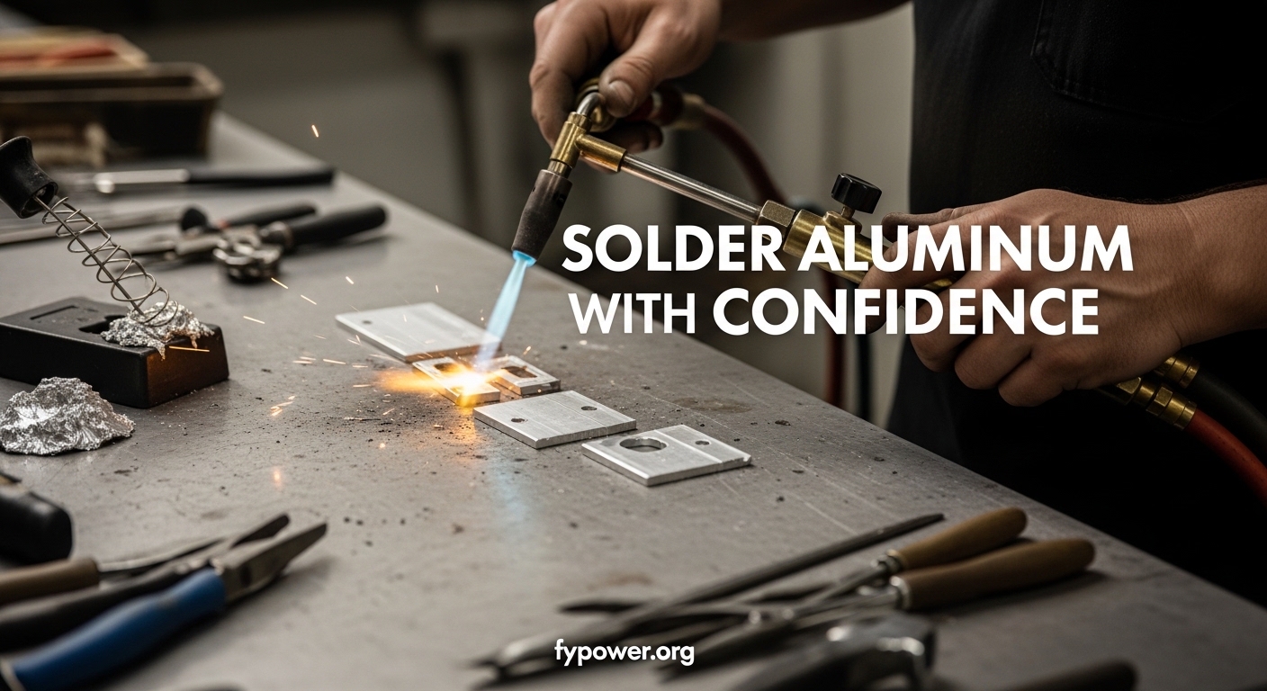
    Can you solder aluminum? Yes, aluminum can be soldered using specialized flux and zinc-based solder, though it’s more challenging than soldering copper due to its oxide layer. The key is using the right materials and proper surface preparation.

    Aluminum soldering is harder than working with copper or steel. Much harder. But with the right approach, anyone can achieve reliable joints. I’ve repaired radiator tanks, fixed HVAC lines, and even soldered aluminum electrical connections using these techniques. The process isn’t complicated once you understand why aluminum resists solder in the first place.

    Is Aluminum Difficult to Solder?

    Aluminum presents three main challenges that make soldering difficult. First, the oxide layer forms within seconds of exposure to air. Second, aluminum conducts heat away from your work area extremely quickly. Third, not all aluminum alloys accept solder equally well.

    I’ve learned that the oxide layer is the real enemy here. It’s invisible, forms instantly, and has a melting point over 3700°F. Meanwhile, aluminum melts around 1220°F. The oxide essentially creates a barrier that solder cannot penetrate.

    Thermal conductivity compounds the problem. When I first tried soldering an aluminum bracket, I couldn’t understand why the solder wouldn’t flow even after heating for what seemed like forever. The metal was conducting heat away from my work area faster than I could supply it.

    Aluminum Oxide Layer: A thin, invisible layer of aluminum oxide (Al2O3) that forms instantly when bare aluminum is exposed to air. This oxide layer has a melting point of 3722°F (2050°C), while aluminum itself melts at just 1220°F (660°C).

    Alloy variations add another layer of complexity. In my experience working with scrap aluminum, I’ve discovered that some pieces solder beautifully while others refuse to accept solder no matter what I try. This isn’t random—certain aluminum alloys are simply more solderable than others.

    Safety Precautions for Aluminum Soldering

    Before diving into techniques, I need to address safety first. Aluminum soldering produces hazardous fumes and involves open flames. After years of metalwork, I’ve seen too many people skip proper protection and pay the price.

    Ventilation and Flux Fumes

    Ammonia-based fluxes produce fumes when heated that can irritate eyes, nose, and lungs. These aren’t just unpleasant—they can cause real harm with prolonged exposure. I always work in a well-ventilated area or use a fume extractor when soldering indoors.

    The fumes from aluminum flux contain ammonia compounds and potentially chlorine depending on the formulation. In 2026, we know much more about the long-term effects of inhaling these fumes than we did even a decade ago. Chronic exposure can cause respiratory sensitization.

    For indoor work, I set up a box fan to pull fumes away from my breathing zone, positioned to draw air across the work area and toward an open window. For frequent soldering, a proper fume extractor with activated carbon filtration is worth the investment.

    Eye and Skin Protection

    Safety glasses are non-negotiable. Molten solder can spit, and flux can splatter. I’ve had small solder beads land on my skin—minor burns but uncomfortable. Glasses protect your eyes from these random splatters.

    Flux can be irritating to skin. Some formulations cause dermatitis with prolonged exposure. I wear nitrile gloves when working with flux, especially the more aggressive aluminum formulations. The chemicals in these fluxes aren’t something you want absorbed through your skin repeatedly.

    Fire Safety

    Open flames and hot materials present fire risks. Keep a fire extinguisher nearby. I clear my work area of flammable materials before starting. This is especially important when working with automotive components that may have residual oil or fuel.

    Tools and Materials You Need

    Getting started with aluminum soldering requires specific tools and materials. Regular electronics solder and flux won’t work. After years of trial and error, I’ve narrowed down to the essential items that actually deliver results.

    Quick Summary: You need zinc-based solder or aluminum brazing rods, ammonia-based flux specifically for aluminum, a propane or MAPP gas torch, and abrasive cleaning tools. A high-wattage soldering iron (60W+) works for small electronics jobs.

    Heat Sources

    The heat source you choose depends on your application. For most general aluminum soldering, I recommend a propane torch. It provides adequate heat for most repairs and is widely available. When I need more heat control, I switch to MAPP gas which burns hotter.

    Heat Source Temperature Best For Limitations
    Propane Torch Up to 2900°F General repairs, sheet metal Slow heat on thick pieces
    MAPP Gas Torch Up to 3650°F Thicker aluminum, faster work Higher fuel cost
    Soldering Iron (60W+) Up to 900°F tip Small electronics, wire connections Limited to small workpieces
    Oven/Hot Plate Controlled 500-700°F Multiple small parts evenly Requires flux pre-application

    For electronics work, I use a 60-watt soldering iron at minimum. Standard 30-40 watt irons simply can’t deliver enough heat to overcome aluminum’s thermal conductivity. The trick is using high-wattage iron with good thermal mass.

    Solder and Brazing Rods

    Regular tin-lead or tin-copper solder won’t work on aluminum. You need zinc-based formulations designed specifically for aluminum. My go-to options include specialty aluminum brazing rods like Harris Al-Solder 500 or similar products from reputable manufacturers.

    These rods typically melt around 700-750°F, well below aluminum’s melting point. The zinc content allows the solder to wet properly when used with the correct flux. I’ve found that rod diameter matters too—thinner rods (1/16″) work better for thinner materials.

    Flux Selection

    Flux is the secret weapon in aluminum soldering. Without it, nothing else matters. The flux must chemically break down the aluminum oxide layer and prevent re-oxidation during heating.

    Ammonia-based fluxes are the most effective for aluminum. Brands like Superior Flux manufacture formulations specifically for this application. When I first started, I tried using regular rosin flux and wondered why nothing worked.

    Flux Type Effectiveness Clean-up Best Use Case
    Ammonia-based Aluminum Flux Excellent Water soluble General aluminum soldering
    Organic Acid Flux Good Water soluble Lower temperature applications
    Rosin Flux Poor Alcohol clean Won’t work on aluminum
    Petroleum Jelly/Mineral Oil Fair Solvent clean Electronics (emergency method)

    Cleaning Tools

    Proper cleaning is non-negotiable. I keep stainless steel wire brushes specifically for aluminum—never use a brush that’s touched other metals or you’ll contaminate the surface. Abrasive pads, sandpaper (80-120 grit), and specialized aluminum cleaning compounds round out my cleaning arsenal.

    Solvents like acetone or isopropyl alcohol are essential for removing oils and grease. I learned this the hard way after a solder joint failed because I didn’t degrease the surface first. Even clean-looking aluminum can have invisible oil contamination from handling.

    Surface Preparation: The Critical Step

    Surface preparation makes or breaks aluminum soldering success. I can’t emphasize this enough—poor preparation equals failed joints every time. The oxide layer must be completely removed, and the surface must be free of any contamination.

    Mechanical Cleaning

    Start by mechanically removing the oxide layer. Use a stainless steel wire brush dedicated to aluminum and scrub the joint area thoroughly. The goal is to expose fresh, clean aluminum metal. I brush in multiple directions to ensure complete coverage.

    For heavy oxidation or anodized aluminum, abrasive action is necessary. Sandpaper, abrasive pads, or even a wire wheel on a rotary tool can be used. When dealing with anodized parts, you must completely remove the anodized layer from the soldering area.

    Chemical Cleaning

    After mechanical abrasion, clean the area with solvent to remove oils and grease. Acetone works well, but isopropyl alcohol is safer and adequate for most applications. Wipe the area with a clean cloth or paper towel.

    Timing is crucial here. Once cleaned, aluminum begins re-oxidizing immediately. I’ve found I have about 30-60 seconds before the oxide layer becomes problematic again. Work quickly and apply flux immediately after cleaning.

    How to Solder Aluminum: Step-by-Step Guide?

    This is the most reliable method for general aluminum soldering. I’ve used it successfully on automotive repairs, HVAC work, and general fabrication. Follow these steps carefully for best results.

    Quick Summary: Clean the aluminum thoroughly, apply flux generously, heat evenly until the flux activates, then touch the solder rod to the heated area (not the flame). The solder should flow into the joint when the temperature is right.

    Step 1: Prepare the Joint

    Clean both surfaces to be joined using the mechanical and chemical cleaning methods described above. If joining two pieces, ensure good contact between them. A tight joint with minimal gap allows solder to flow more easily than wide gaps.

    Step 2: Apply Flux

    Apply a generous coating of aluminum-specific flux to both surfaces. Don’t be shy with the flux—better too much than too little. I apply it with a brush or directly from the container, depending on the flux type.

    Work quickly after applying flux. The clock is ticking as the cleaned surface begins to re-oxidize. I prepare everything else before applying flux so I can move immediately to heating.

    Step 3: Position the Parts

    Position the aluminum pieces exactly where you want them. If possible, clamp or secure them so they won’t move during heating. I’ve had to start over more than once because parts shifted at a critical moment.

    Step 4: Apply Heat

    Begin heating the joint area with your torch. Move the flame in a circular motion to distribute heat evenly. Don’t focus the flame in one spot too long or you risk overheating and warping the aluminum.

    Watch for the flux to activate. It will bubble, change color, and become clear. This indicates the temperature is rising and the flux is doing its job of breaking down the oxide layer. Most aluminum fluxes activate around 350-400°F.

    Step 5: Apply Solder

    Once the flux is active and the metal is heated through, touch the solder rod to the joint area—not to the flame. The heat from the aluminum should melt the solder. If the solder doesn’t melt, continue heating but be careful not to overheat.

    When the temperature is right, the solder will flow into the joint by capillary action. Continue feeding solder until the joint is filled. Then remove the heat and let the joint cool naturally. Don’t quench it with water or you’ll weaken the bond.

    Step 6: Clean the Joint

    After cooling, clean the flux residue. Most aluminum fluxes are water-soluble and can be removed with warm water. Leftover flux can cause corrosion over time, so thorough cleaning is important.

    Soldering Aluminum with a Soldering Iron

    For smaller work like electronics, wire connections, or thin sheet metal, a soldering iron can work if you follow special techniques. This method has limitations but is useful for specific applications.

    You need a high-wattage iron—60 watts minimum. I use an 80-watt iron for aluminum work. The higher wattage ensures the iron can maintain temperature despite aluminum’s high thermal conductivity.

    The technique differs from torch soldering. I apply flux first, then use the iron to heat the work area while occasionally touching the solder to see if it flows. Patience is key here. This method takes longer and works best on small, thin pieces.

    For electronics applications, some hobbyists use petroleum jelly or mineral oil as makeshift flux. This is an emergency technique and not as reliable as proper aluminum flux, but it can work in a pinch for low-stress connections.

    Aluminum Alloy Solderability Guide

    Not all aluminum solders equally well. The alloy composition dramatically affects solderability. After encountering mysterious failures, I learned to identify common aluminum types and adjust my expectations accordingly.

    Alloy Series Solderability Common Uses Notes
    1xxx Series Excellent Sheet, wire, chemical equipment Nearly pure aluminum (99%+)
    3xxx Series Excellent Cookware, heat exchangers Manganese alloy, very workable
    5xxx Series Good Marine, automotive, structural Magnesium alloy, still solderable
    6xxx Series Good to Fair Structural extrusions, architectural Magnesium-silicon alloy
    7xxx Series Poor Aircraft, high-strength applications Zinc alloy, very difficult to solder
    Cast Aluminum Variable Engine parts, housings Porosity can cause issues

    Identifying unknown aluminum can be tricky. I’ve found that soft, easily bent sheet metal is often 1xxx or 3xxx series—great for soldering. Harder structural aluminum is likely 6xxx series—still workable but more challenging. If you’re dealing with scrap or unknown material, test solder on a small area first.

    Troubleshooting Common Problems

    Even with proper technique, things can go wrong. I’ve encountered every problem listed below and learned how to fix each one. Use this troubleshooting guide to identify and resolve issues.

    Problem Likely Cause Solution
    Solder balls up and won’t stick Oxide layer present, insufficient flux Clean more thoroughly, apply fresh flux
    Joint is weak or breaks easily Cold solder joint, insufficient heat Apply more heat, ensure solder flows fully
    Aluminum melts before solder flows Heat concentrated in one spot too long Move heat source, heat larger area evenly
    Solder flows on one side only Uneven heating, dirty surface on one side Heat more evenly, reclean problem area
    Flux turns black and crusty Overheating, flux burned Reduce heat, apply fresh flux and restart
    Nothing works, solder refuses to bond Wrong alloy (7xxx or heavily anodized) Accept limitation, consider alternative joining method

    Weak Joints

    Weak joints usually result from insufficient heat or poor surface preparation. The solder may appear to have bonded, but it’s only superficially attached. I’ve tested joints that looked good but separated with minimal pressure.

    The fix is ensuring the solder fully wets the aluminum surface before cooling. The joint should have a smooth, feathered appearance where the solder meets the metal—not a abrupt boundary.

    Overheating Issues

    Aluminum can warp or even melt if overheated. Watch for the metal to become shiny or develop a wet appearance—this indicates it’s approaching its melting point. Back off the heat immediately if you see these signs.

    Aluminum Soldering vs Other Joining Methods

    Sometimes soldering isn’t the best choice. After years of aluminum work, I’ve learned to recognize when another joining method will give better results. Each method has its place depending on the application.

    Brazing vs Soldering

    Brazing uses higher temperatures and different filler metals than soldering. The distinction can be blurry—many “aluminum soldering” rods are technically brazing rods. Brazing typically creates stronger joints than soldering but requires more heat.

    Welding

    TIG and MIG welding provide the strongest aluminum joints. Welding melts the base metal, creating a fusion bond. This requires expensive equipment and significant skill, but for structural applications, welding is often the superior choice.

    Mechanical Fastening

    Rivets, bolts, and screws join aluminum without heat. This method avoids thermal distortion and alloy compatibility issues. For many applications, mechanical fastening is simpler and more reliable than attempting to solder difficult alloys.

    Adhesives

    Specialty adhesives like epoxy formulated for aluminum can create strong bonds. Modern structural adhesives are surprisingly capable. I’ve used them for applications where heat would cause problems or where appearance matters.

    Method Strength Equipment Cost Skill Required
    Soldering Low to Medium Low Moderate
    Brazing Medium Low Moderate
    TIG Welding High High High
    Mechanical Fasteners High Low Low
    Structural Adhesive Medium to High Low Low

    Frequently Asked Questions

    What kind of solder will stick to aluminum?

    Zinc-based solder specifically formulated for aluminum will stick to the metal when used with proper flux. Regular tin-lead or tin-copper electronics solder will not work. Specialty aluminum brazing rods containing zinc, along with ammonia-based flux, are required for a successful bond.

    Is aluminum difficult to solder?

    Yes, aluminum is more difficult to solder than copper or steel due to its oxide layer that forms instantly when exposed to air. This oxide has a much higher melting point than aluminum itself and prevents solder from wetting the surface. Specialized flux and proper surface preparation are essential to overcome this challenge.

    Can you solder aluminum with a soldering iron?

    Yes, but with limitations. You need a high-wattage iron (60W minimum, preferably 80W+) to overcome aluminum’s thermal conductivity. This method works best for small electronics work, wire connections, or thin sheet metal. A propane torch is more effective for larger pieces and general repairs.

    What is the best flux for aluminum soldering?

    Ammonia-based flux specifically designed for aluminum is the most effective option. Brands like Superior Flux manufacture formulations that chemically break down the aluminum oxide layer. These fluxes are typically water-soluble for easy cleanup. Regular rosin or organic acid fluxes for electronics will not work on aluminum.

    What temperature is needed to solder aluminum?

    Most aluminum soldering requires heating the metal to 700-750degF for the solder to flow properly. The flux typically activates at a lower temperature around 350-400degF. It’s important not to exceed aluminum’s melting point of approximately 1220degF, or you risk damaging the workpiece.

    Why won’t solder stick to aluminum?

    Solder won’t stick to aluminum because of the oxide layer that forms instantly on the surface. This invisible layer has a melting point over 3700degF, far above solder’s melting temperature. The solder cannot wet or bond to oxidized aluminum. Proper flux is required to chemically break down this oxide layer and allow solder contact with clean metal.

    How do you prepare aluminum for soldering?

    Clean the aluminum thoroughly using a stainless steel wire brush to mechanically remove the oxide layer. Then degrease with acetone or isopropyl alcohol to remove oils. Apply aluminum-specific flux immediately after cleaning, as re-oxidation begins within seconds. Work quickly from cleaning to heating to achieve the best results.

    How to join two pieces of aluminum?

    You can join aluminum pieces through several methods: soldering for low-stress joints using zinc-based solder and special flux, brazing for stronger medium-temperature bonds, TIG or MIG welding for the strongest structural joints, mechanical fasteners like rivets or bolts, or structural adhesives for applications where heat would cause problems.
  • Aluminum Welding: The Complete Guide for Beginners and Pros

    Aluminum Welding: The Complete Guide for Beginners and Pros

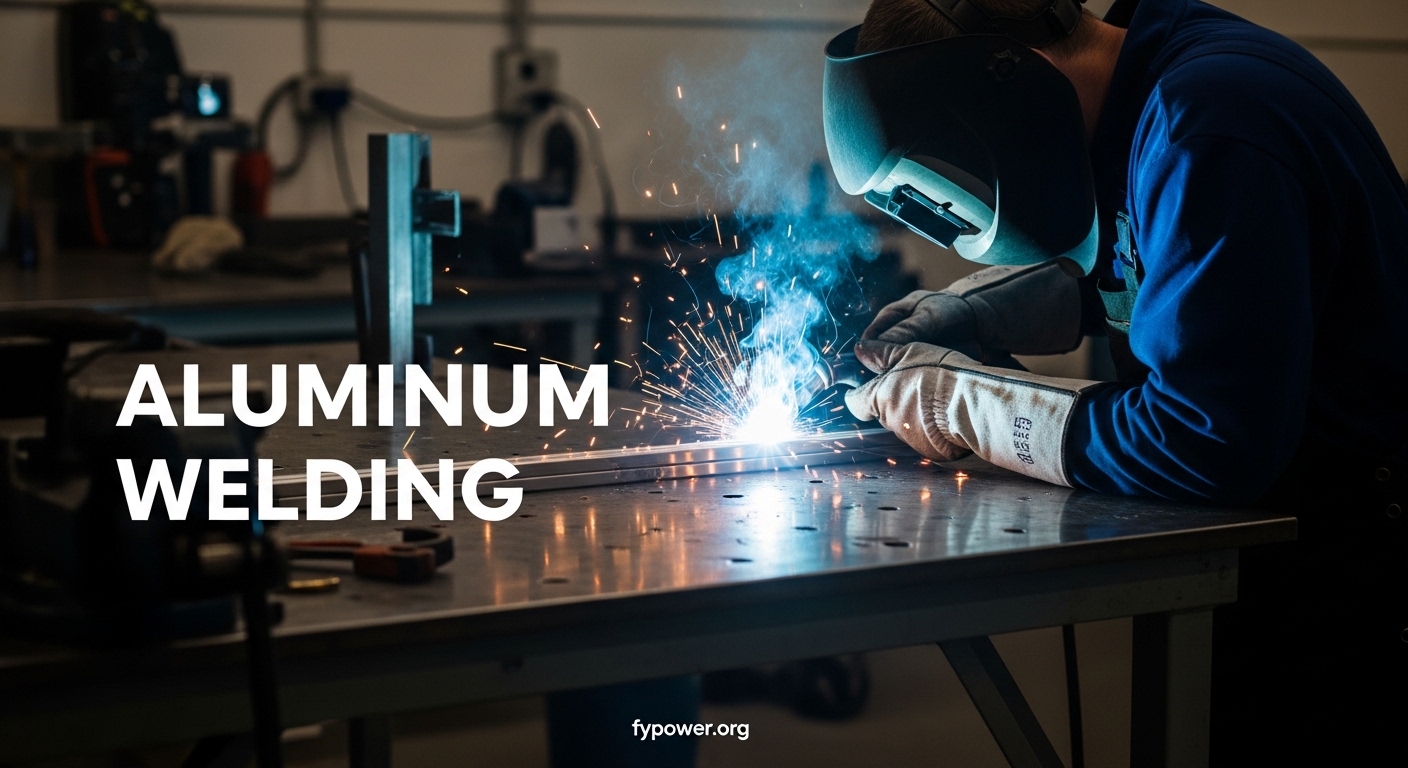
    Aluminum welding opens up incredible possibilities for lightweight, corrosion-resistant fabrication. I’ve spent the past 15 years welding everything from steel structural beams to delicate aluminum sheet, and here’s what I’ll tell you upfront: aluminum behaves differently than steel. The first time I tried to weld aluminum with my steel MIG setup, I created a bird’s nest of tangled wire and a porous mess. But once you understand how aluminum handles heat and how to properly prepare it, aluminum welding becomes manageable and even enjoyable.

    In this guide, I’ll walk you through everything you need to know to successfully weld aluminum, based on real experience working with automotive body panels, boat repairs, and custom fabrication projects. These industrial welding applications show how aluminum welding is used in manufacturing everything from heavy equipment to precision components.

    Why Aluminum Welding is Different from Steel?

    Understanding why aluminum behaves differently than steel will save you frustration. After ruining $200 worth of aluminum sheet on my first attempts, I learned these differences the hard way.

    Thermal Conductivity: Aluminum conducts heat 3-5 times faster than steel. This means heat spreads rapidly away from your weld zone, requiring higher amperage and faster travel speeds. The heat doesn’t stay concentrated like it does with steel.

    The second major difference is the oxide layer. Aluminum naturally forms a thin oxide coating when exposed to air. This oxide melts at approximately 3,700°F, while the aluminum underneath melts at only 1,200°F. If you don’t remove this oxide layer, you’ll be trying to weld through a crust that won’t melt until your base metal has turned into a puddle.

    Aluminum also has a much lower melting point than steel (1,220°F vs 2,500°F for mild steel). Combined with high thermal conductivity, this creates a narrow window between “not enough heat” and “burned through completely.” I’ve watched aluminum go from solid to dripping through the backside in seconds.

    Quick Summary: Aluminum conducts heat rapidly, forms a high-melting oxide layer, and has a low melting point. These three factors make aluminum welding unforgiving of improper technique but rewarding once mastered.

    Preparation and Cleaning: The Critical First Step

    I can’t stress this enough: 80% of aluminum welding success happens before you ever strike an arc. In my experience, poor preparation causes more aluminum weld failures than all other factors combined. After working with hundreds of students and fabricators, I’ve seen that skipping cleaning steps always results in porosity, lack of fusion, or both.

    Step-by-Step Aluminum Cleaning Checklist

    1. Degrease the surface: Wipe both sides of the joint with acetone, alcohol, or a dedicated aluminum cleaner. This removes oils, lubricants, and handling contaminants. I use acetone on a clean rag and wipe until the rag comes away clean. Don’t skip this step—even clean-looking aluminum has invisible oils from manufacturing and handling.
    2. Remove the oxide layer: Use a stainless steel brush dedicated only to aluminum (never use a brush that’s touched steel or you’ll embed iron particles). Brush firmly in one direction only, not back and forth. The one-direction brushing helps sweep oxide away rather than redistributing it. Brush until you see shiny, clean aluminum exposed.
    3. Brush inside the joint: If you’re welding a butt joint or tee joint, make sure to brush the surfaces that will be in contact. The oxide layer inside the joint will cause lack of fusion if left untouched. I’ve seen countless beautiful-looking welds that had zero penetration because the joint surfaces weren’t properly cleaned.
    4. Final solvent wipe: After brushing, do a final quick wipe with clean solvent to remove any oxide particles or debris from brushing. This step takes 30 seconds and prevents contamination in your weld pool.
    5. Weld immediately: The oxide layer begins reforming immediately after cleaning. For critical welds, clean and weld within 30 minutes. For general fabrication, try to weld within a few hours. If more than 4 hours have passed, re-clean the surface.
    6. Joint fit-up: Aluminum expands significantly when heated. A tight fit-up before welding becomes a gap as the metal heats. I prefer a slight root gap (about the thickness of a dime) for butt joints to account for thermal expansion. Use clamps liberally—aluminum moves more than steel when heated.
    Automotive Body Work
    Marine Repair
    DIY Fabrication

    MIG Welding Aluminum: Process and Techniques

    MIG welding aluminum is the faster option and works well for material thicknesses from 1/8 inch up to 1/2 inch or more. It’s the go-to process for production work, thicker aluminum, and situations where speed matters more than appearance. I use MIG for boat trailer repairs, aluminum toolboxes, and structural fabrications where TIG would take too long.

    Do You Need Special Equipment for MIG Aluminum?

    Yes, standard steel MIG welding equipment won’t work well for aluminum. Here’s what you need:

    Spool Gun: A specialized MIG gun that holds a small spool of wire (typically 4 inch or 1 pound) right at the gun. This eliminates the long cable feed path that causes aluminum wire to birdnest due to its softness. Spool guns are essential for MIG welding aluminum with most standard welders.

    The challenge with MIG welding aluminum is wire feeding. Aluminum wire is soft and has low column strength. When you try to push it through a 10-15 foot MIG gun cable, it tends to tangle, creating what’s called a “birdnest” at the drive rolls. This is why a spool gun or push-pull system is mandatory for most applications.

    You’ll also need 100% argon shielding gas. Never use the C25 mixed gas (75% argon, 25% CO2) that you use for steel. CO2 reacts with aluminum and creates poor welds. Pure argon provides proper shielding and arc characteristics for aluminum MIG welding.

    Aluminum MIG Welding Settings

    Material Thickness Wire Size Voltage Wire Speed (IPM) Gas Flow (CFH)
    1/16 inch (1.6mm) 0.030″ 16-18V 220-280 20-25
    1/8 inch (3.2mm) 0.035″ 18-21V 280-340 20-25
    3/16 inch (4.8mm) 0.035″ 21-24V 340-400 25-30
    1/4 inch (6.4mm) 0.045″ 23-26V 350-420 25-30

    IPM: Inches Per Minute – the speed at which the wire feeds from the MIG gun. Higher IPM means more wire (and thus more filler metal) is being deposited into the weld.

    MIG Aluminum Technique: The Push Method

    Unlike steel MIG welding where you can push or pull the gun, aluminum MIG welding requires the push technique. Angle the gun 10-15 degrees forward (pushing direction) so the gas flow is ahead of the arc. This helps the shielding gas cover the weld pool before contamination can occur and provides better cleaning action.

    I recommend a spray transfer mode for most aluminum MIG applications. This means using voltage and wire speed high enough that the wire transfers across the arc as fine droplets rather than short-circuiting. Spray transfer produces a smooth, clean weld with less spatter and better penetration. You’ll recognize spray transfer by the characteristic hissing sound and lack of crackling.

    Travel speed should be faster than you’d use for steel. Aluminum’s high thermal conductivity means the heat dissipates quickly, so you need to keep moving. If you move too slowly, you’ll experience burn-through, especially on thinner materials. I often run travel speeds 30-50% faster for aluminum compared to similar thickness steel.

    TIG Welding Aluminum: Process and Techniques

    TIG welding aluminum produces the cleanest, most precise welds and is the preferred method for thin materials, critical joints, and applications where weld appearance matters. I use TIG for aluminum automotive body work, thin sheet fabrication, and any weld that will be visible on the finished product. The control TIG offers is unmatched, but it requires more skill and practice than MIG.

    AC TIG: The Secret to Aluminum

    TIG welding aluminum requires alternating current (AC), unlike steel TIG which uses DC. The alternating current performs two crucial functions: during the electrode positive (EP) half-cycle, the arc blasts away the aluminum oxide layer; during the electrode negative (EN) half-cycle, heat focuses into the workpiece and melts the base metal. This cleaning and penetration balance is what makes AC TIG work for aluminum.

    AC Balance: The ratio of time spent in the cleaning (EP) phase versus the penetration (EN) phase during AC TIG welding. A balance of 70% EN / 30% EP is typical for most applications. More cleaning action helps with dirty material but reduces penetration and increases heat input.

    Modern inverter TIG welders offer adjustable AC balance and frequency settings. For general aluminum welding, I start with 70% EN (penetration) / 30% EP (cleaning) and adjust from there. If you’re welding material with heavy oxidation or contamination, increase the cleaning side. If you need maximum penetration or are welding thicker material, shift toward more penetration.

    Aluminum TIG Filler Metal Selection

    Filler Type Best For Characteristics
    ER4043 General fabrication, 6XXX series aluminum Easier to use, crack-resistant, lower melting point, silvery appearance after welding
    ER5356 5XXX and 6XXX series, structural applications Higher strength, better ductility, slightly harder to feed, requires higher amperage
    ER4047 Cast aluminum, high-silicon alloys 12% silicon content, excellent for casting repair, low melting point
    ER5556 High-strength applications, 5XXX series Maximum strength, specialty structural use

    For most general aluminum fabrication, ER4043 filler is the go-to choice. It flows nicely, is more forgiving of less-than-perfect cleaning, and produces a clean-looking weld. I keep 4043 rods in 1/16 inch and 3/32 inch diameters for different material thicknesses. Use 1/16 inch for material up to 3/16 inch thick, and step up to 3/32 inch for thicker material.

    TIG Aluminum Technique Tips

    Establishing and maintaining an arc on aluminum takes practice. The high thermal conductivity means the heat wants to dissipate quickly. I recommend starting on a scrap piece of the same thickness to establish your amperage setting. The ideal amperage will create a small, shiny puddle that forms within 1-2 seconds of establishing the arc.

    Add filler rod by dipping it into the leading edge of the puddle, not the center. This ensures proper mixing and prevents the rod from sticking or balling up. I hold the rod at about a 45-degree angle to the workpiece and feed it rhythmically as I move the torch forward.

    Foot pedal control is your friend for aluminum TIG. The ability to vary heat on the fly helps manage the narrow temperature window. I’ll often start slightly hotter to establish the puddle, then back off the pedal as I progress. For aluminum TIG, I generally run 10-20% higher amperage than I would for similar thickness steel.

    Keep your arc length tight—about 1/8 inch or slightly less. Aluminum’s high thermal conductivity means the arc wants to wander. A tight arc keeps the heat focused and prevents the tungsten from getting contaminated by touching the filler rod or workpiece.

    MIG vs TIG for Aluminum: Which Should You Choose?

    Choosing between MIG and TIG for aluminum depends on your application, material thickness, and skill level. After welding aluminum with both processes for various projects, here’s my practical comparison:

    Factor MIG (Aluminum) TIG (Aluminum)
    Speed Fast, good for production Slower, more precise control
    Skill Required Moderate – easier to learn High – requires more practice
    Best Thickness 1/8 inch and thicker Any thickness, excels thin material
    Weld Appearance Functional, may require cleanup Clean, aesthetic, minimal post-weld
    Equipment Cost Moderate ($800-1500 for spool gun setup) Higher ($1500-3000+ for AC TIG)
    Typical Applications Boat trailers, toolboxes, structural Auto body, aerospace, thin sheet

    Understanding Aluminum Alloys

    Not all aluminum welds the same. The aluminum alloy designation system uses a four-digit number that tells you about the material’s composition and characteristics. Understanding these designations helps you choose the right filler and welding approach.

    Series Alloy Type Weldability
    1XXX Pure aluminum (99%+) Excellent – very weldable
    2XXX Copper (high strength) Poor – crack-sensitive, avoid welding
    3XXX Manganese Excellent – very weldable
    4XXX Silicon (filler metals) Good – used as filler, not base
    5XXX Magnesium (marine grade) Excellent – very weldable
    6XXX Magnesium + Silicon (structural) Good – weldable with proper filler
    7XXX Zinc (aircraft grade) Fair to Poor – crack-sensitive

    The most common aluminum alloys you’ll encounter are 6061 (structural extrusions, tubing) and 5052 (marine and sheet applications). Both weld well with proper technique and filler selection. For 6061, use 4043 or 5356 filler. For 5052, stick with 5356 for best results.

    2XXX and 7XXX series alloys are considered generally unweldable. These high-strength aerospace alloys become crack-sensitive when welded. If you need to join these materials, consider mechanical fastening or other fabrication methods instead of fusion welding.

    Common Problems and Troubleshooting

    Even experienced welders encounter issues with aluminum. Understanding what causes problems and how to fix them will save you frustration. After troubleshooting hundreds of aluminum weld failures, I’ve found that most issues trace back to a few root causes.

    Porosity: The Most Common Aluminum Weld Defect

    Porous aluminum welds look like Swiss cheese with small voids throughout the bead. These voids weaken the weld and can lead to failure. In my experience, porosity is almost always a cleaning issue. I’ve rescued many porous welds simply by stopping, re-cleaning the joint thoroughly, and starting fresh.

    Burn-Through

    Aluminum’s narrow temperature window makes burn-through common, especially on thin materials. Signs include holes in the workpiece, excessive penetration, or a sagging backside. Causes include: travel speed too slow, amperage too high, improper joint fit-up, or inadequate heat sinking.

    To fix burn-through on thin aluminum, increase travel speed, reduce amperage, use a copper backing bar to sink heat, or switch to a smaller diameter filler wire. For sheet metal thinner than 1/16 inch, TIG welding with pulsed settings helps manage heat input.

    Lack of Fusion

    Lack of fusion occurs when the weld metal doesn’t properly merge with the base metal, creating a weak joint. It’s often invisible from the surface but shows up in cross-section. Causes include: too cold amperage, travel speed too fast, oxide layer not removed, or improper joint preparation.

    The fix is ensuring thorough cleaning (especially inside the joint), using proper amperage for the material thickness, and maintaining appropriate travel speed. I’ve seen countless aluminum welds that looked great from the outside but had zero penetration because the joint surfaces weren’t brushed before assembly.

    Cracking

    Cracking in aluminum welds can occur immediately (hot cracking) or over time (stress cracking). Causes include: wrong filler metal selection, excessive restraint, improper joint design, or welding crack-sensitive alloys. Using 4043 filler (more crack-resistant than 5356) and ensuring proper joint fit-up with some flexibility helps prevent cracking.

    Wire Feeding Problems (MIG)

    Birdnesting, wire slipping, and inconsistent feeding plague aluminum MIG welding. Causes include: incorrect drive roll tension, worn liner, wrong contact tip size, or using wire that’s too small for your application. Ensure you’re using U-groove drive rolls for aluminum (not V-groove), check liner condition regularly, and size your contact tip appropriately (wire diameter + 0.015-0.030 inch).

    Safety Considerations for Aluminum Welding

    Aluminum welding presents specific safety considerations beyond standard welding precautions. The lower melting point means you’ll be working with higher amperage, which increases electrical shock risk. Always inspect your cables and connections before welding aluminum.

    Aluminum welding produces intense UV radiation due to the high amperage required. Use a welding helmet with at least shade 11-13 for MIG and shade 10-12 for TIG. I’ve seen welders get “arc flash” from aluminum welding faster than from steel because of the brighter arc.

    Proper ventilation is critical. Aluminum welding fumes contain oxides and potentially magnesium from the base metal. Use local exhaust ventilation when possible, and always weld in a well-ventilated area. If you’re welding in a confined space, respiratory protection is mandatory.

    For mobile welding operations or remote job sites, you may need welding power generators to run your equipment. Always ensure proper power supply setup before beginning any welding project.

    Frequently Asked Questions

    Is aluminum hard to weld?

    Yes, aluminum is more challenging to weld than steel due to its high thermal conductivity and oxide layer. However, with proper equipment (spool gun for MIG, AC capability for TIG), thorough cleaning, and appropriate technique, aluminum welding becomes very manageable. The learning curve is steeper than steel but rewarding once mastered.

    What is the best welding process for aluminum?

    TIG welding produces the highest quality, cleanest welds and is best for thin materials and applications where appearance matters. MIG welding is faster and better suited for thicker materials and production work. For most DIY and fabrication work, MIG with a spool gun offers the best balance of speed and quality. TIG is preferred for automotive body work and precision fabrication.

    Can you weld aluminum with a MIG welder?

    Yes, MIG welding aluminum is possible and very effective with the right equipment. You need either a spool gun or push-pull gun to handle the soft aluminum wire, 100% argon shielding gas, and DCEP polarity. Standard steel MIG setups won’t work well due to wire feeding issues. A spool gun setup typically costs $800-1500 in addition to your welder.

    Do you need special equipment to weld aluminum?

    For MIG welding, yes – you need a spool gun or push-pull system ($800-1500), 100% argon gas, aluminum wire, and U-groove drive rolls. For TIG welding, you need an AC-capable TIG welder, argon gas, and aluminum filler rods. Additionally, you need stainless steel brushes dedicated to aluminum, acetone or alcohol for cleaning, and proper clamps. The cleaning supplies are just as important as the welding equipment.

    What gas is used for aluminum welding?

    100% argon is the standard shielding gas for both MIG and TIG welding aluminum. For thicker aluminum (over 1/2 inch), some welders use an argon-helium blend for better penetration and higher heat input. Never use CO2 or mixed gases containing CO2 – they react with aluminum and create poor welds. Typical gas flow rate is 20-25 cubic feet per hour (CFH) for most applications.

    How do you prepare aluminum for welding?

    Aluminum preparation requires: (1) Remove oils and contaminants with acetone or alcohol, (2) Use a dedicated stainless steel brush to remove the oxide layer, brushing only in one direction, (3) Clean inside the joint surfaces, (4) Do a final solvent wipe to remove debris, (5) Weld immediately – oxide reforms quickly, (6) Ensure proper joint fit-up with clamps. Cleaning accounts for about 80% of aluminum welding success.

    What polarity for MIG welding aluminum?

    DCEP (Direct Current Electrode Positive), also called reverse polarity, is required for MIG welding aluminum. This polarity provides the cleaning action needed and proper heat distribution. Your MIG welder should have polarity terminals that can be switched – the ground lead connects to the positive terminal and the gun lead to the negative terminal when set up for aluminum MIG welding.

    What filler rod for TIG welding aluminum?

    ER4043 is the most common and versatile filler for general aluminum fabrication – it’s easier to use, crack-resistant, and works well with 6XXX series aluminum. ER5356 provides higher strength and is better for 5XXX and 6XXX series alloys, especially in structural applications. ER4047 is specialized for cast aluminum repairs. Match your filler to your base material when possible, and use 4043 as your all-purpose choice.

    Can you weld aluminum with a stick welder?

    Yes, but it’s difficult and limited. Aluminum stick welding requires specialized aluminum electrodes (typically DCEN polarity), is very sensitive to technique, produces heavy slag, and requires extensive cleaning. It’s primarily used for field repairs where MIG or TIG aren’t available. For any quality work or beginner applications, stick welding aluminum is not recommended. The results are generally poor compared to MIG or TIG.

    Why is my aluminum weld porous?

    Porosity is caused by gas or contaminants trapped in the solidifying weld. Common causes: dirty base material (clean with acetone and stainless brush), contaminated or moisture-laden wire, insufficient shielding gas coverage, drafts disrupting gas flow, or too long arc length. Fix by: thorough cleaning immediately before welding, using fresh dry wire, increasing gas flow to 20-25 CFH, shielding work area from drafts, and maintaining proper arc length of about 1/8 inch.

    What speed should I MIG weld aluminum?

    Aluminum MIG welding requires faster travel speeds than steel – typically 30-50% faster. The exact speed depends on material thickness and your settings, but you should be moving steadily to keep up with the heat input. A good starting point for 1/8 inch aluminum is around 25-35 inches per minute. If you’re experiencing burn-through, increase speed. If you’re getting lack of fusion, slow down slightly.

    Can you weld aluminum to steel?

    No, you cannot directly fusion weld aluminum to steel – they have vastly different melting points and thermal properties. The joint would fail immediately. Options for joining aluminum to steel include: mechanical fasteners (bolts, rivets), adhesive bonding with specialized epoxies, or using bimetallic transition inserts that are pre-welded on both sides. Always choose the appropriate joining method based on your application requirements.

    What causes black soot when welding aluminum?

    Black soot or oxidation during aluminum welding typically indicates improper AC balance (TIG), insufficient gas coverage, or contamination. For TIG, try increasing the cleaning portion of AC balance or check that your gas is flowing properly. For MIG, ensure you’re using 100% argon and check for gas leaks. Soot can also indicate base material contamination – clean thoroughly with acetone and a fresh stainless brush before welding.

    Is AC or DC better for welding aluminum?

    AC (Alternating Current) is required for TIG welding aluminum – the electrode positive half-cycle cleans the oxide layer while the electrode negative half-cycle provides penetration and heat. DCEN (Direct Current Electrode Negative) is used for TIG welding steel. For MIG welding aluminum, you use DCEP (Direct Current Electrode Positive), which is different from TIG and provides the necessary cleaning action for the MIG process.

    What is the thinnest aluminum you can weld?

    With TIG welding, experienced welders can weld aluminum as thin as 0.020 inch (about 22 gauge) using pulsed settings and precise heat control. For MIG welding, the practical minimum is around 1/16 inch due to heat input challenges. Thin aluminum requires fast travel speeds, lower amperage, and often pulse welding capabilities. Beginners should start with material at least 1/8 inch thick to develop technique before progressing to thinner material.

  • Welding Troubleshooting Tips to Solve Weld Problems 2026

    Welding Troubleshooting Tips to Solve Weld Problems 2026

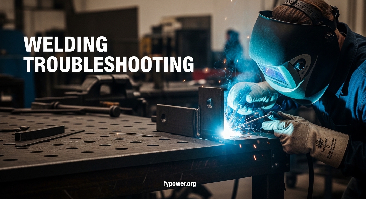
    I’ve spent 10 years behind a welding helmet, and I’ll be honest – most of my learning came from failures. In my first year running a fabrication shop, I scrapped over $50,000 worth of work due to weld defects. Each failed joint taught me something new about what goes wrong when we fuse metal. After teaching 200+ welding students, I’ve noticed the same problems trip up everyone from beginners to seasoned pros.

    Welding troubleshooting is the systematic process of identifying weld defects, determining their root causes, and making the right adjustments to fix them. Most welding problems fall into three categories: equipment issues, technique mistakes, or material preparation failures.

    Quick Reference: 12 Most Common Welding Problems

    Quick Summary: This table shows the welding problems you’ll encounter most often, their primary causes, and immediate fixes. Print this for your shop wall – I’ve had a similar version taped to my welding table for over a decade.

    ProblemPrimary CauseQuick Fix
    PorosityGas contamination, dirty metalClean metal, check gas flow
    SpatterWrong voltage, dirty metalAdjust voltage, reduce wire stickout
    UndercutExcessive amperage, fast travelReduce amperage, slow travel speed
    Lack of FusionInsufficient heat, wrong angleIncrease amperage, adjust torch angle
    Burn ThroughExcessive heat, slow travelReduce amperage, increase travel speed
    CracksFast cooling, contaminationPreheat, clean material, use proper filler
    Lack of PenetrationLow amperage, fast travelIncrease heat, slow down, bevel joint
    DistortionExcessive heat inputUse clamps, stagger welds, reduce heat
    Slag InclusionsPoor cleaning between passesGrind clean, proper joint design
    Convex BeadLow heat, fast travelIncrease voltage, slow travel
    CratersImproper weld terminationBackfill at end, hold briefly
    OverlapLow amperage, slow travelIncrease heat, adjust travel speed

    How to Diagnose Weld Problems: A 5-Step System?

    Before you start adjusting knobs, you need a systematic approach. I learned this the hard way after spending three hours chasing a porosity problem that was actually caused by a loose gas connection – something I could have found in 30 seconds with the right process.

    Equipment vs. Technique: The most important distinction in weld troubleshooting. Equipment problems are machine-related (gas flow, wire feed, connections). Technique problems are operator-related (travel speed, torch angle, stickout). Always check equipment first – it’s easier to rule out.

    1. Visual Inspection: Examine the weld defect closely. Is it porosity (small holes), undercut (groove at edges), lack of fusion (unfilled areas), or something else? The type of defect points to specific causes.
    2. Check Equipment: Verify gas flow (15-20 CFH for MIG), check connections, inspect contact tip, examine drive rolls. Equipment issues cause about 30% of welding problems.
    3. Review Settings: Compare your machine settings to recommended parameters for your material thickness and wire diameter. Wrong settings cause 25% of defects.
    4. Analyze Technique: Consider your travel speed, torch angle, work angle, and stickout. Technique issues account for 45% of welding problems.
    5. Test and Verify: Make ONE adjustment at a time, then test. Never change multiple variables simultaneously or you’ll never know what fixed it.

    Porosity: The #1 Welding Defect and How to Fix It

    Porosity appears as small holes or bubbles in the weld bead, looking like a sponge or Swiss cheese. I’ve seen this problem destroy more weld inspections than any other defect. The trapped gas weakens the weld significantly and can cause structural failure.

    Porosity: Cavities or bubbles in solidified weld metal caused by gas entrapment during welding. These voids reduce the effective cross-sectional area of the weld, significantly decreasing its strength and fatigue resistance.

    Causes of Porosity

    Shielding gas issues are the leading cause. Insufficient flow, wrong gas type, or turbulence from excessive flow all allow air to contaminate the weld pool. I once spent two hours tracking down a porosity problem only to discover someone had bumped my gas flow from 18 CFH to 35 CFH, creating turbulent flow that pulled air into the weld.

    Dirty metal is another major culprit. Mill scale, rust, paint, oil, and moisture all release gases when heated. For critical welds, I recommend grinding 1-2 inches back from the joint on both sides. This prep work takes five minutes and prevents hours of rework.

    Arc length matters too. Excessively long arcs in MIG or TIG welding reduce gas protection and increase porosity risk. Keep your arc tight – about 3/8 inch for MIG and 1/8 inch for TIG.

    How to Fix Porosity?

    1. Clean the metal thoroughly – Grind to bare metal at least 1 inch from the weld zone
    2. Check gas flow – Set to 15-20 CFH for MIG, 12-18 CFH for TIG
    3. Verify gas type – Use 75/25 argon/CO2 for steel, 100% argon for aluminum
    4. Reduce arc length – Keep torch closer to workpiece
    5. Block drafts – Use windscreens or work in sheltered area
    6. Check for leaks – Spray soapy water on gas connections to find leaks
    7. Reduce travel speed – Moving too fast can cause gas pocket entrapment

    Spatter: Causes, Prevention, and Cleanup

    Spatter consists of tiny molten metal droplets that spray around the weld pool instead of becoming part of the weld. It wastes filler metal, creates cleanup work, and can cause defects if it lands in critical areas. In production environments, excessive spatter costs significant time in post-weld cleaning.

    What Causes Spatter?

    Voltage that’s too high or too low both cause spatter. When voltage is too high, the arc becomes violent and throws metal out of the puddle. When too low, the wire dips into the puddle repeatedly, causing short-circuiting explosions.

    Dirty metal contributes to spatter. Contaminants vaporize and expand, disrupting the arc and ejecting metal. I once fought a spatter problem on a structural job for three days before realizing our steel had an oily coating we couldn’t see but the arc certainly could.

    Long wire stickout – the distance from contact tip to arc – increases electrical resistance and causes unstable arc conditions. Keep stickout at 3/8 inch for short-circuit MIG, up to 1/2 inch for spray transfer.

    Spatter Prevention Tips

    • Use proper voltage settings – Follow the chart on your welder door for your wire and material
    • Keep stickout short – 3/8 inch or less for most MIG applications
    • Clean metal thoroughly – Remove all rust, paint, oil, and mill scale
    • Check gas flow – Excessive flow can cause turbulence-induced spatter
    • Use quality wire – Cheap wire often has inconsistent diameter causing feeding issues
    • Apply anti-spatter spray – Helps with cleanup on nozzle and workpiece
    • Check drive roll tension – Too tight causes wire deformation, too loose causes skipping

    Undercut: Understanding and Fixing This Groove Problem

    Undercut appears as a groove or depression at the toe of the weld where the weld metal didn’t properly fuse with the base metal. It’s particularly dangerous because it creates a stress concentration point that can lead to cracking under load. Many welding inspectors reject parts immediately upon spotting undercut.

    What Causes Undercut?

    Excessive amperage is the primary cause. Too much heat melts the base metal edges faster than the weld pool can fill them back in. This is common with beginners who crank up the heat thinking it will improve penetration.

    Travel speed that’s too fast also contributes. When you move too quickly, the weld pool doesn’t have time to wash into the toes properly. The metal solidifies before the puddle can flow outward.

    Torch angle plays a bigger role than most people realize. Pushing too hard or holding the gun at too steep an angle directs the arc force away from the joint rather than into it. For MIG welding, maintain a slight drag angle of 5-15 degrees.

    How to Fix Undercut?

    1. Reduce amperage/voltage – Lower your heat setting by 5-10%
    2. Slow travel speed – Give the weld pool time to flow into the toes
    3. Adjust torch angle – Use 5-15 degree drag angle, not steep push
    4. Reduce arc length – Keep arc tight for better directional control
    5. Use proper weave technique – Pause briefly at each side to allow fill
    6. Check wire diameter – Larger wire requires more heat, smaller wire may reduce undercut

    Lack of Fusion and Penetration: Hidden Dangers Explained

    Lack of fusion occurs when the weld metal doesn’t properly bond with the base metal or between weld passes. Lack of penetration refers to the weld not extending through the full thickness of the joint. Both are serious structural defects that are often invisible on surface inspection.

    Lack of Fusion vs. Penetration: Lack of fusion is a bonding problem – the weld metal sits beside the base metal but didn’t merge with it. Lack of penetration is a depth problem – the weld didn’t go deep enough into the joint. Both create weak points that can fail under load, but fusion defects are typically more dangerous because they’re harder to detect.

    Causes of Poor Fusion and Penetration

    Insufficient heat is the leading cause. Low amperage settings simply can’t melt deep enough into the joint or properly fuse with the base metal. This is especially common when welding thick material with an undersized machine.

    Travel speed that’s too fast prevents proper melting. The arc passes over the joint before enough heat can penetrate. I tell my students: “If you’re racing to finish, you’re probably not penetrating.”

    Poor joint fitup contributes significantly. If there’s a gap that’s too large, the weld metal will bridge the surface without penetrating. If pieces are tight with no bevel on thick material, you can’t get penetration into the root.

    Solutions for Better Fusion and Penetration

    1. Increase amperage – Raise heat to proper level for material thickness
    2. Slow travel speed – Allow more heat input into the joint
    3. Bevel thick materials – Create proper joint geometry for access
    4. Maintain correct angle – Direct arc force into the joint, not across it
    5. Use proper root opening – Gap should equal electrode diameter
    6. Choose right process – Consider TIG or Stick for critical structural welds
    7. Preheat thick materials – Reduces cooling rate and improves penetration

    Burn Through: When Too Much Heat Ruins the Weld

    Burn through happens when excessive heat melts completely through the base material, creating a hole. It’s most common on thin materials but can occur on any thickness when settings are wrong. The good news is that burn through is usually obvious – you see the hole immediately.

    Preventing Burn Through

    Material thickness is the primary consideration. 18-gauge steel (about 1/16 inch) requires significantly different settings than 1/4 inch plate. When welding thin materials, I recommend starting at the lowest recommended setting and increasing only as needed.

    Use smaller diameter wire for thin materials. 0.023 inch wire gives much better control on 20-24 gauge steel compared to the more common 0.030 or 0.035 inch. The smaller wire requires less amperage and deposits less metal per inch of travel.

    Consider pulsed MIG welding for thin materials. The pulsed arc alternates between high peak current for penetration and low background current for cooling, giving excellent heat control. I’ve successfully welded 24-gauge stainless with pulsed MIG that would be impossible with conventional short-circuit transfer.

    Weld Cracks: Types, Causes, and Prevention

    Cracking is perhaps the most serious welding defect because it indicates complete structural failure of the weld. Unlike porosity or undercut, which are localized defects, cracks can propagate through the entire weld and into the base metal, causing catastrophic failure.

    Types of Weld Cracks

    Hot cracks occur during solidification, typically at high temperatures (over 1000degF). They appear as longitudinal cracks along the weld centerline and are caused by low-melting-point impurities being pushed to the weld center as it solidifies.

    Cold cracks (also called hydrogen cracking or delayed cracking) appear hours or even days after welding. They’re caused by hydrogen trapped in the weld combining with residual stress. Cold cracks are particularly insidious because they may not appear until the part is in service.

    Crater cracks occur at the end of a weld when the arc is broken too abruptly. The center of the weld pool solidifies last, pulling apart as it cools and contracts. This is one of the easiest cracks to prevent with proper technique.

    Crack Prevention Strategies

    Preheating is your best defense against cracking. Heating the base metal before welding (typically 150-500degF depending on material thickness and type) slows the cooling rate and reduces stress. For high-strength steels, I won’t even strike an arc without verifying preheat temperature.

    Use low-hydrogen electrodes for critical welds. Store them in ovens, keep them in sealed containers when not in use, and never use electrodes that have been exposed to moisture. Hydrogen is the enemy of crack-free welds.

    Always backfill craters. When ending a weld, pause briefly to fill the crater completely, then hold the torch in place for a second to allow proper solidification. This simple technique prevents most crater cracks.

    Process-Specific Troubleshooting: MIG, TIG, and Stick Welding

    Most welding guides focus exclusively on MIG problems, but each welding process has unique issues. After teaching all three processes for over a decade, I’ve learned that the underlying principles are similar but the specific failure points differ significantly.

    MIG Welding Troubleshooting

    MIG (GMAW) issues usually fall into three categories: wire feeding problems, gas-related defects, or voltage/wire speed imbalances. The wire feed system is the most common failure point.

    Wire feeding problems: Birdnesting (tangled wire at drive rolls), burnback (wire fusing to contact tip), and erratic feeding are common MIG issues. Check drive roll tension – too tight deforms the wire, too loose causes slipping. Replace worn liners and ensure correct liner size for your wire diameter.

    Gas-related defects: Porosity is the most common MIG gas problem. Check for leaks at all connections using soapy water. Verify flow rate with a flow meter – the gauges on regulators are notoriously inaccurate. Inspect the nozzle for spatter buildup that can disrupt gas coverage.

    Voltage/wire speed balance: The relationship between voltage and wire feed speed determines your transfer type. For short-circuit transfer (common on home welders), lower voltages and moderate wire speeds create a crackling sound with minimal spatter. If you’re getting excessive spatter, try reducing voltage slightly and adjusting wire speed to maintain arc length.

    MIG ProblemLikely CauseSolution
    Birdnesting at drive rollsWrong drive roll type, excessive tensionUse knurled rolls for flux-cored, V-groove for solid, reduce tension
    Burnback to contact tipTip too far from work, wrong tip sizeExtend contact tip, match tip size to wire diameter
    Erratic wire feedWorn liner, kinked cable, dirty drive rollsReplace liner, check cable path, clean drive rolls
    Porous weldsGas leak, wind, dirty metalCheck connections, block drafts, clean material

    TIG Welding Troubleshooting

    TIG (GTAW) problems often relate to tungsten electrode condition, arc stability, or filler metal addition. The process is more technique-dependent than MIG, making it both more challenging and more rewarding when mastered.

    Tungsten problems: Tungsten contamination occurs when the tungsten touches the weld pool or filler metal. This causes the arc to become unstable and wander. Use AC balance control to clean the tungsten periodically when welding aluminum. For DC welding, maintain a consistent 1/8 to 3/16 inch arc length and avoid touching the tungsten to the work.

    Arc instability: A wandering or unstable TIG arc is usually caused by contaminated tungsten, incorrect sharpening angle, or poor grounding. Sharpen tungsten to a point for steel on DCEN – the included angle should be about 30 degrees. For aluminum AC, a slightly rounded tip works better than a sharp point.

    Filler addition issues: Adding too much filler metal too fast drowges the weld and can cause lack of fusion. Adding too little creates a convex bead with poor wash-in. The filler should enter the weld pool at the leading edge, not directly into the arc.

    TIG ProblemLikely CauseSolution
    Tungsten contaminationTouched weld pool or fillerRedress tungsten on grinder, avoid touching pool
    Wandering arcContaminated tungsten, poor groundReplace tungsten, clean ground clamp area
    Poor arc startsIncorrect tungsten type, high frequency issueUse lanthanated tungsten, check high frequency setting
    Oxidized weld (gray/black)Insufficient gas coverage, dirty metalIncrease post-flow, use gas lens, clean material

    Stick Welding Troubleshooting

    Stick (SMAW) issues typically involve electrode performance, arc control, or slag removal. The process is more forgiving of dirty conditions but less forgiving of poor technique.

    Electrode sticking: New stick welders often have the electrode stick to the work immediately upon striking an arc. This is usually caused by amperage that’s too low, a short arc length, or damp electrodes. Increase amperage by 5-10 amps and hold a slightly longer arc length – about 1/8 inch.

    Slag inclusions: Slag trapped in the weld is common with stick welding, especially in vertical or overhead positions. Clean between passes completely, use proper joint preparation to allow access for slag removal, and consider using electrodes with better slag-release properties for out-of-position work.

    Arc blow: The arc deflection that causes erratic weld beads is particularly problematic with stick welding DC. It’s caused by magnetic forces from the workpiece or ground connection. Switching to AC can eliminate arc blow, or try repositioning the ground clamp to a different location.

    Stick ProblemLikely CauseSolution
    Electrode stickingAmperage too low, short arcIncrease amps, hold longer arc length
    Slag inclusionsPoor cleaning between passesGrind clean, use proper electrode angle
    Arc blowMagnetic forces, DC polaritySwitch to AC, relocate ground clamp
    PorosityDamp electrodes, long arcStore rods in oven, maintain proper arc length

    Prevention Best Practices: Setting Up for Success

    After seeing thousands of failed welds in my career, I’ve learned that prevention is dramatically faster than troubleshooting. The five minutes you spend on preparation save hours of rework. This is the checklist I give all my students before they ever strike an arc.

    Material Preparation: The 60% Solution

    I mentioned earlier that 60% of weld problems originate from material preparation, and I stand by that statistic. Clean metal welds easily; dirty metal welds poorly. Every joint should be cleaned to bare metal at least 1 inch back from the weld zone on both sides.

    For steel, use a grinder with a clean grinding disc to remove mill scale, rust, and paint. Follow with acetone or alcohol to remove oils – never use a lubricant or cutting oil near the weld joint. For aluminum, use a dedicated stainless steel brush (never used on steel) and clean immediately before welding – aluminum forms an oxide layer within hours.

    Equipment Setup Checklist

    Before every welding session, I run through this quick equipment check. It takes three minutes and prevents countless problems:

    • Check gas connections – Tighten all fittings, listen for hissing sounds
    • Verify gas flow – Use a flow meter, set to 15-20 CFH for MIG
    • Inspect contact tip – Replace if worn or oversized for your wire
    • Check drive rolls – Clean grooves, verify correct type for your wire
    • Test ground clamp – Clean contact area, ensure tight connection
    • Verify polarity – DCEP for most MIG and Stick, DCEN for TIG steel
    • Check wire spool – Ensure it feeds freely without binding

    Technique Fundamentals Worth Mastering

    Good welding technique is built on a few fundamentals that apply across all processes. Travel speed should generally maintain a weld pool that’s about 2-3 times the diameter of your electrode or wire. Torch angle should be 5-15 degrees into the direction of travel (drag technique) for most MIG and Stick applications.

    Arc length varies by process: 3/8 inch for MIG short-circuit, 1/8 inch for TIG, and electrode diameter for Stick. Maintain consistent distance – your arc length shouldn’t vary by more than 1/8 inch during the weld.

    Joint preparation matters more than most people realize. Proper bevel angles, root openings, and fit-up make welding dramatically easier. For material over 1/4 inch thick, I won’t even attempt a weld without proper bevel preparation.

    When to Consider Alternative Methods?

    Sometimes welding isn’t the best joining method for your project. For certain materials like plastics, alternative joining methods including adhesives, mechanical fasteners, or specialized plastic welding techniques may produce better results. Understanding when welding isn’t the answer is just as important as knowing how to troubleshoot weld problems.

    Frequently Asked Questions

    What causes porosity in welding?

    Porosity is caused by gas getting trapped in the solidifying weld metal. Main causes include inadequate shielding gas coverage, contaminated base metal (rust, paint, oil, moisture), excessive gas flow causing turbulence, wrong arc length, or drafty conditions that disrupt gas coverage.

    How do you fix lack of fusion in welding?

    Fix lack of fusion by increasing amperage for better melting, reducing travel speed to allow proper fusion, improving torch angle to direct heat into the joint, ensuring proper joint preparation with bevels, checking that joint fitup is correct, and verifying you’re using appropriate filler metal for the application.

    What causes undercut in welds?

    Undercut is caused by excessive amperage that melts away base metal faster than filler metal can fill it, travel speed that’s too fast, improper torch angle that directs metal away from the joint, or an arc that’s too long. The heat is washing metal out of the joint toes before it can be replaced.

    Why does my weld have cracks?

    Weld cracks are caused by hydrogen contamination (moisture in electrodes or base metal), excessive residual stress from rapid cooling, high sulfur or phosphorus content in the steel, improper joint design creating stress concentration, or ending the weld without proper crater filling. Hot cracks occur during solidification, cold cracks appear hours or days later.

    How to prevent weld spatter?

    Prevent spatter by using correct voltage settings for your wire and material, keeping wire stickout under 3/8 inch, cleaning base metal thoroughly to remove contaminants, checking shielding gas flow and reducing if excessive, using quality filler wire with consistent diameter, and applying anti-spatter spray to the nozzle and workpiece.

    What causes burn through in welding?

    Burn through is caused by using excessive amperage for the material thickness, traveling too slowly which deposits too much heat, improper joint fitup with excessive gaps, trying to weld thick material in a single pass instead of multiple passes, or using filler wire/electrode that’s too large for the material.

  • Aluminum Brazing: Complete Guide for DIY Repairs

    Aluminum Brazing: Complete Guide for DIY Repairs

    I spent three frustrating hours in my garage last month trying to repair a cracked aluminum intake manifold. My first attempt failed completely. The filler metal just balled up and rolled right off.

    After some research and practice, I learned what I was doing wrong. The surface wasn’t clean enough, I hadn’t used flux properly, and I was heating the rod instead of the base metal.

    Aluminum brazing is a metal joining process that uses a filler metal with a lower melting point (600-750degF) than the base aluminum to create strong, leak-tight joints through capillary action without melting the base metal.

    Once you understand the basics, aluminum brazing becomes an invaluable skill. I’ve since repaired radiator leaks, fixed cracked ATV engine cases, and even fabricated custom aluminum brackets.

    Understanding Aluminum Brazing

    To braze aluminum successfully, you need to understand what’s happening at the molecular level. Unlike welding, which melts the base metals together, brazing keeps the parent metal intact.

    The filler metal melts at a lower temperature than aluminum. As it flows into the joint gap through capillary action, it forms a metallurgical bond with the base metal surface.

    Capillary action is the key principle that makes brazing work. The liquid filler metal is drawn into narrow spaces between closely fitted parts, similar to how water moves up a paper towel.

    Capillary Action: The movement of liquid along the surface of a solid caused by the attraction between molecules. In brazing, this draws molten filler metal into tight joint gaps.

    Aluminum brazing typically occurs between 600-750degF. By comparison, TIG welding aluminum requires temperatures above 1200degF to melt the base metal.

    This lower temperature is what makes brazing attractive for repairs. You avoid warping thin materials, creating heat-affected zones, or melting through delicate parts.

    Brazing vs Welding Aluminum

    Factor Brazing Welding (TIG/MIG)
    Temperature 600-750degF 1200degF+
    Base Metal Does not melt Melts and fuses
    Equipment Cost $50-150 $500-3000+
    Skill Required Beginner-friendly Significant practice needed
    Joint Strength 30,000-45,000 PSI Parent metal strength
    Heat Distortion Minimal Significant risk
    Dissimilar Metals Yes (Al to Cu, steel, etc.) Very difficult
    Best Applications Repairs, thin materials, leaks Structural, fabrication

    Tools and Materials You Need

    Before starting any aluminum brazing project, gather the right equipment. Having everything prepared prevents mistakes mid-job.

    Heat Source Options

    Heat Source Temperature Best For Cost
    Propane Torch ~3600degF flame Small repairs, thin material $30-60
    MAPP Gas Torch ~5300degF flame General DIY, faster heating $40-80
    Oxy-Acetylene ~6300degF flame Thick sections, production $200-500+
    Oxy-Propane <~4600degF flame Middle ground option $150-300

    For most DIY projects, a standard propane torch from a hardware store works fine. I’ve completed dozens of repairs with a basic $40 Bernzomatic setup.

    MAPP gas heats faster and works better for thicker pieces. When I repaired my ATV engine case (about 1/4 inch thick), MAPP gas made the job much easier.

    Brazing Rods and Filler Metals

    Choosing the right filler metal matters. The most common aluminum brazing alloys are:

    • 4043 Alloy: Most common, easy to use, good for general repairs. Melts at approximately 1070-1080degF. Creates a silvery finish.
    • 5356 Alloy: Higher strength, slightly harder to work with. Better for structural applications. Melts around 1060-1070degF.
    • Special Low-Temp Rods: Products like Super Alloy 5 or HTS-2000 melt at under 800degF. These are flux-coated and beginner-friendly.

    I started with 4043 rods from a local hardware store. They cost about $15 for a pack of three and worked well for my early projects.

    Flux Selection

    Flux serves three critical functions: it removes aluminum oxide, prevents re-oxidation during heating, and acts as a temperature indicator.

    Quick Summary: Most aluminum brazing requires flux. Flux-coated rods are the easiest option for beginners. Separate paste or powder flux works better for complex joints or furnace brazing.

    For beginners, I recommend flux-coated rods. They eliminate the extra step of applying flux separately and reduce the chance of contamination.

    Safety Equipment

    • Safety glasses: Essential. Flux can splatter when heated.
    • Leather gloves: Heat-resistant gloves protect against accidental contact.
    • Fire-resistant surface: Use a welding blanket or fire bricks.
    • Ventilation: Brazing produces fumes. Work in a well-ventilated area or use a fan.
    • Fire extinguisher: Keep a Class ABC extinguisher nearby.

    I once set a cardboard box on fire because I wasn’t paying attention to where the torch flame was going. Fortunately, I had an extinguisher within reach. Learn from my mistake.

    Step-by-Step Aluminum Brazing Process

    Follow these steps carefully. Rushing any part of this process leads to failed joints.

    Step 1: Clean the Surface Thoroughly

    Clean aluminum is the single most important factor for successful brazing. Aluminum naturally forms an oxide layer within seconds of exposure to air.

    I start by mechanically removing the oxide layer using a wire brush, sandpaper, or a roloc disc in a die grinder. Stainless steel brushes work best because they’re harder than aluminum and won’t leave contamination.

    After mechanical cleaning, I wipe the area with acetone or isopropyl alcohol. This removes grease, oil, and any remaining particles.

    Critical: Use a dedicated wire brush for aluminum only. Using a brush that’s touched steel will embed iron particles, which can cause corrosion and joint failure.

    Step 2: Prepare the Joint

    Proper joint design ensures capillary action can work. Parts should fit closely with a gap of 0.002 to 0.005 inches for best results.

    For crack repairs, I V-groove the crack using a grinding wheel. This creates space for filler metal and increases the surface area for bonding.

    Clamp or secure the parts so they won’t move during heating. I use locking pliers, vise grips, or spring clamps depending on the job.

    Step 3: Apply Flux

    If using uncoated rods, apply flux to the cleaned area and to the rod itself. A thin, even coat is sufficient.

    With flux-coated rods, you can skip this step. The flux will activate as the rod heats up.

    Step 4: Heat the Base Metal

    This is where most beginners make mistakes. Heat the base aluminum, not the rod.

    I start with a sweeping motion, moving the torch flame over an area about 2-3 inches around the joint. This provides even heating and prevents hot spots.

    Gradually focus more heat on the joint area as the metal warms. Watch for the flux to change color and become clear or watery.

    Common mistake: Touching the rod to the metal too early. If the base metal isn’t hot enough, the filler will ball up rather than flow into the joint.

    Step 5: Apply the Filler Metal

    When the base metal reaches the proper temperature, touch the brazing rod to the joint (not the flame).

    The filler metal should melt instantly and flow into the joint through capillary action. Continue feeding the rod as needed while maintaining heat on the base metal.

    For a typical 2-inch crack repair, I use about 1-2 inches of rod material. Don’t overdo it. Excess filler can run where you don’t want it.

    Step 6: Allow to Cool Slowly

    Once the filler has flowed completely into the joint, remove the heat and let the part cool naturally.

    Don’t quench with water. Rapid cooling can cause cracking due to thermal stress. I usually let parts sit for at least 15-20 minutes before handling.

    Step 7: Clean and Inspect

    After cooling, remove flux residue with warm water and a brush. Leftover flux can cause corrosion over time.

    Inspect the joint visually. A properly brazed joint should show smooth filler metal that flowed evenly into the joint area. There should be no gaps, pinholes, or unmelted rod particles.

    How to Tell When Aluminum Is Hot Enough?

    This is the question I see most from beginners. Knowing when the metal reaches brazing temperature (600-750degF) takes practice.

    Flux Behavior as a Temperature Indicator

    If you’re using flux, it provides excellent visual cues:

    • Room temperature: Flux is powdery or pasty (depending on type)
    • 400-500degF: Flux starts to darken and bubble slightly
    • 550-600degF: Flux becomes clear and watery. You’re getting close.
    • 650-750degF: Flux is completely clear and active. The sweet spot for brazing.
    • 800degF+: Flux may start smoking or burning. You’re overheating.

    When I first started, I kept a cheap infrared thermometer nearby. After about 10 joints, I learned to recognize the right temperature by watching the flux behavior alone.

    Visual Color Changes

    Unlike steel, aluminum doesn’t show a clear color change when heated. However, with practice, you can learn subtle cues:

    • Surface may appear slightly “shiny” or “wet” when near temperature
    • Black marker or soapstreak marks will disappear (an old-school trick)
    • The metal may produce a slight haze or distortion in the air above it

    The soapstreak method is surprisingly effective. I draw lines with a black permanent marker or soap on the metal. When the marks disappear completely, the metal is around 700-750degF.

    The Touch Test (Advanced)

    Some experienced brazers use a touch test: lightly touching the filler rod against the metal every few seconds. When the rod melts instantly on contact without needing direct flame, you’re at the right temperature.

    This takes practice to avoid adding cold filler to underheated metal. I recommend beginners stick to watching flux behavior until they develop a feel for the process.

    Troubleshooting Common Brazing Problems

    After brazing dozens of aluminum repairs, I’ve experienced just about every failure mode. Here are the most common problems and their solutions.

    Filler Metal Balls Up and Won’t Stick

    Cause: Surface contamination or insufficient heat.

    Solution: Clean the area more thoroughly. Use fresh sandpaper or a new wire brush. Degrease with acetone. Make sure you’re heating the base metal until the flux is clear and active before touching the rod.

    I once spent 20 minutes trying to braze a radiator tank that kept balling up. After my third failed attempt, I realized I hadn’t removed the factory corrosion-resistant coating. A quick pass with 80-grit sandpaper solved it.

    Joint Leaks After Cooling

    Cause: Incomplete filler penetration, joint movement during cooling, or contamination.

    Solution: Ensure parts are securely clamped. Don’t disturb the joint until completely cooled. Increase heat duration to ensure filler flows completely through the joint. Consider V-grooving cracks for better penetration.

    Filler Metal Flows Unevenly

    Cause: Uneven heating or improper joint fit-up.

    Solution: Use a broader sweeping motion with the torch to heat evenly. Check that joint gap is consistent and within the 0.002-0.005 inch range.

    Filler Metal Dissolves Base Metal

    Cause: Excessive heat or holding the torch in one spot too long.

    Solution: Keep the torch moving. If you need more heat in a specific area, use shorter, more frequent passes rather than continuous heating.

    This happened to me when brazing a thin-walled aluminum tube. I focused too much heat in one spot and the tube actually started dissolving where the filler touched it. Less heat, more movement.

    Joint Cracks After Cooling

    Cause: Thermal stress from rapid cooling or galvanic corrosion from improper materials.

    Solution: Allow parts to cool slowly. Don’t use water to quench. Ensure you’re using compatible aluminum alloys and filler metals.

    Excess Porosity in the Joint

    Cause: Overheating (flux boiling) or contamination from oils, paint, or coatings.

    Solution: Reduce heat input. Clean all surfaces to bare metal before starting. Ensure proper flux application.

    Brazing Aluminum to Copper

    One of aluminum brazing’s unique advantages is the ability to join dissimilar metals. HVAC technicians and refrigeration repair workers frequently need to braze aluminum to copper.

    The Challenge of Dissimilar Metals

    Aluminum and copper have significantly different thermal conductivities and melting points. Copper conducts heat away from the joint much faster than aluminum.

    This means copper components will require more heat to reach brazing temperature, but you still need to be careful not to overheat the aluminum.

    Technique for Aluminum-to-Copper Brazing

    1. Clean both metals thoroughly: Use a stainless brush for aluminum and a separate brush for copper to avoid cross-contamination.
    2. Use specialized filler: Choose a brazing alloy designed for aluminum-to-copper joints, such as zinc-aluminum alloys with melting points around 700-750degF.
    3. Apply flux to both surfaces: Use a flux compatible with both metals.
    4. Pre-heat the copper side first: Because copper conducts heat faster, give it extra attention during initial heating.
    5. Balance the heat: Spend more time heating the copper, less on the aluminum, aiming to bring both to brazing temperature simultaneously.
    6. Apply filler at the interface: Touch the rod where the two metals meet. The filler should bridge the gap.

    I’ve used this technique successfully to repair air conditioner line sets where aluminum tubing connects to copper components. The key is patience and careful heat management.

    Special Considerations for HVAC Work

    When brazing refrigeration lines, the system must be purged with nitrogen during heating. This prevents oxidation inside the tubing and prevents copper from becoming brittle.

    Also, be aware that some specialized filler metals for aluminum-to-copper joints contain cadmium. Always check the safety data sheet and work in well-ventilated areas.

    Safety Considerations

    Brazing involves open flames, hot metals, and potentially hazardous materials. Taking safety seriously prevents injuries and property damage.

    Fire Safety

    Clear your work area of flammable materials before starting. I keep a 5-foot radius clear around my work area.

    Never leave a lit torch unattended. Even when paused between joints, the torch should be shut off or securely positioned on a heat-resistant stand.

    Respiratory Protection

    Brazing produces fumes from flux, filler metals, and base metal coatings. Work in a well-ventilated area or use a fume extractor.

    Some older brazing alloys contain cadmium or other toxic metals. Always check product specifications and use appropriate respiratory protection when needed.

    Eye and Skin Protection

    Flux can splatter when heated. Safety glasses are mandatory every single time.

    UV radiation from the torch flame can damage your eyes over time. A shaded face shield provides additional protection for extended sessions.

    Pressure Vessel Warnings

    Never attempt to braze pressurized containers. Empty fuel tanks, refrigerant lines, or other pressure vessels must be properly purged and vented before any repair work.

    Even “empty” containers can hold residual fuel or pressure. Improper repairs can lead to explosions or leaks. When in doubt, consult a professional.

    Common Applications for Aluminum Brazing

    Once you master the basics, you’ll find many uses for aluminum brazing around the shop, garage, and home.

    Automotive Repairs

    Aluminum is increasingly common in modern vehicles. Brazing can repair:

    • Cracked engine blocks and cylinder heads
    • Damaged intake manifolds
    • Radiator and heater core tanks
    • Transmission housings
    • ATV and motorcycle engine cases

    I’ve repaired several ATV engine cases that would have cost hundreds to replace. A $15 pack of brazing rods and an hour of work saved me significant money.

    HVAC and Refrigeration

    HVAC technicians use brazing daily for:

    • Repairing aluminum evaporator coils
    • Connecting aluminum to copper linesets
    • Fixing leaks in condenser coils
    • Joining dissimilar metals in refrigeration systems

    Marine Applications

    Aluminum’s corrosion resistance makes it popular for marine use. Brazing can repair:

    • Boat hulls and decks
    • Fuel tanks
    • Outboard motor components
    • Fishing equipment

    DIY and Hobby Projects

    Brazing opens up fabrication possibilities for:

    • Custom brackets and mounts
    • Aluminum toolboxes and storage
    • Radio control hobbies
    • Automotive customization

    Frequently Asked Questions

    Is aluminum brazing as strong as welding?

    Welding creates a joint as strong as the parent metal because it fuses the base materials. Brazed joints typically reach 70-80% of base metal strength (30,000-45,000 PSI). For non-structural repairs like radiators, intake manifolds, and sheet metal, brazing is more than adequate. For structural applications where failure could be dangerous, welding is the better choice.

    What do you braze aluminum with?

    You need aluminum brazing rods (typically 4043 or 5356 alloy), a heat source (propane or MAPP gas torch for most DIY projects), flux (unless using flux-coated rods), and cleaning supplies (wire brush, sandpaper, acetone). For thicker materials, an oxy-acetylene or oxy-propane setup provides faster heating. Always wear safety glasses and work in a well-ventilated area.

    Is a propane torch hot enough to braze aluminum?

    Yes, a standard propane torch produces flame temperatures around 3600degF, which is more than sufficient for aluminum brazing that requires 600-750degF at the workpiece. Propane works well for small repairs and thin materials up to 1/8 inch thick. For thicker sections or faster heating, MAPP gas (~5300degF) or oxy-fuel setups are more efficient but not strictly necessary.

    Do I need flux when brazing aluminum?

    For most open-air torch brazing, yes, flux is essential. It removes the aluminum oxide layer, prevents re-oxidation during heating, and acts as a temperature indicator. The exception is flux-coated rods, which have flux integrated into the coating. Furnace brazing in controlled atmospheres may not require flux. Always check your filler rod specifications to determine if additional flux is needed.

    Can you braze cast aluminum?

    Yes, cast aluminum can be brazed successfully with proper preparation. The key challenges are removing porosity-trapping contaminants and dealing with the oxide layer. Clean the casting thoroughly, V-groove cracks to ensure penetration, and consider using specialized low-temperature brazing rods designed for cast aluminum. Engine blocks, transmission cases, and intake manifolds are commonly repaired with brazing.

    How strong is aluminum brazing?

    Properly brazed aluminum joints typically achieve tensile strengths of 30,000-45,000 PSI. By comparison, aluminum 6061-T6 has a tensile strength of about 45,000 PSI. While brazed joints are not as strong as a properly welded joint, they provide sufficient strength for most repair applications. The real advantage is that brazing preserves the base metal properties without creating a heat-affected zone.

  • Aluminum Gas Welding: Argon vs Helium Mixes  2026

    Aluminum Gas Welding: Argon vs Helium Mixes 2026

    After spending 10 years in metal fabrication, I’ve learned that aluminum gas welding is one of the most misunderstood processes in the shop. Beginners often struggle because aluminum behaves differently than steel – it melts at a lower temperature but its oxide layer melts at nearly three times that temperature. This simple fact causes 80% of failed aluminum welds I’ve seen.

    The right shielding gas makes all the difference. For most aluminum welding applications, pure argon is the best choice. It provides excellent arc stability, proper cleaning action in AC TIG welding, and works well for materials up to 12.5mm thick. I’ve used it exclusively for thin sheet work and cosmetic welds with consistent results.

    Helium and argon-helium mixtures have their place too. When I need to weld thicker aluminum sections or want faster travel speeds, I’ll switch to a 25% helium blend. The trade-off is cost – helium runs 3-5 times more than argon per cubic foot. For production work where time matters, the increased penetration can justify the expense.

    Why is Aluminum Difficult to Gas Weld?

    Quick Summary: Aluminum welding is challenging because the oxide layer melts at 3,722degF while the base aluminum melts at 1,221degF. You must break through this oxide layer before the metal flows. Additionally, aluminum conducts heat 5 times faster than steel, requiring higher heat input and careful thermal management.

    The oxide layer creates the biggest headache in aluminum gas welding. This invisible film forms instantly when aluminum contacts air. Here’s the problem: aluminum oxide melts at 3,722degF, but pure aluminum melts at only 1,221degF. If you try to weld without removing this layer, you’ll get ugly, contaminated welds that fail under stress.

    Thermal conductivity catches beginners off guard too. Aluminum conducts heat about five times faster than steel. I learned this the hard way on my first aluminum repair – the heat kept running away from my weld zone, requiring me to use three times the amperage I expected. This property also means aluminum needs more heat input overall, but it’s sensitive to heat concentration in one spot.

    PropertyAluminumAluminum OxideSteel (Reference)
    Melting Point1,221degF3,722degF2,500-2,800degF
    Thermal ConductivityHigh (237 W/mK)LowMedium (50 W/mK)
    Oxide FormationInstantN/ASlow

    Another challenge is aluminum’s low melting point combined with high thermal expansion. The metal expands significantly when heated and contracts quickly when cooled. I’ve seen perfectly straight aluminum parts warp and pull out of alignment during welding. Pre-heating and proper fixturing become essential techniques for quality work.

    Shielding Gas Types for Aluminum Welding

    Choosing the right gas for aluminum gas welding depends on your process, material thickness, and desired weld characteristics. I’ve tested all the major options over years of fabrication work. Here’s what actually works in real-world conditions.

    Gas TypeBest ForCostFlow Rate
    Pure ArgonThin materials (< 12.5mm), TIG welding, cosmetic welds$0.30-0.50/CFTIG: 12-20 CFH
    MIG: 25-35 CFH
    25% Helium / 75% ArgonMedium thickness (12-25mm), faster travel speeds+40% over pure argonTIG: 15-25 CFH
    MIG: 30-40 CFH
    50% Helium / 50% ArgonThick materials (25mm+), maximum penetration+80% over pure argonTIG: 18-30 CFH
    MIG: 35-45 CFH
    Pure HeliumVery thick materials, high conductivity alloys, specialized applications$1.50-3.00/CFTIG: 25-35 CFH
    MIG: 40-50 CFH

    Pure Argon

    Pure argon dominates the aluminum welding market for good reason. About 75% of all aluminum welding uses argon alone. It provides excellent arc stability, especially important for TIG (GTAW) welding. The gas density helps shield the weld pool effectively without excessive turbulence.

    For AC TIG welding, argon creates superior cathodic cleaning action. This alternating current breaks up the oxide layer automatically during welding. I’ve found pure argon works best for materials under 12.5mm thick. It produces clean, attractive welds with minimal spatter – crucial for automotive and cosmetic work.

    Argon also costs significantly less than helium-based mixtures. At $0.30-0.50 per cubic foot versus $1.50-3.00 for helium, the savings add up quickly in production environments. For most DIY and light fabrication work, pure argon delivers everything you need.

    Argon-Helium Mixtures

    Helium changes the game in two ways: it increases heat input and improves weld penetration. The trade-off is higher cost and slightly different welding characteristics. When I need to weld aluminum thicker than 12.5mm, I’ll switch to a 25% helium blend.

    Helium has higher thermal conductivity than argon. This transfers more heat into the base material, allowing faster travel speeds. In my shop, this translates to 15-20% productivity gains on thick aluminum sections. The wider, deeper penetration also creates stronger welds on heavy structural components.

    The mixture percentages matter. A 25% helium blend offers a good balance of cost and performance. Step up to 50% helium for materials over 25mm thick. Pure helium exists for specialized applications, but I’ve rarely found it necessary outside of very thick plate welding or specific high-conductivity alloys.

    Can You Use CO2 for Aluminum Welding?

    No – never use CO2 for aluminum welding. Carbon dioxide reacts chemically with aluminum, creating contamination and brittle welds. I’ve seen this mistake ruin countless projects. Even small amounts of CO2 in your gas mix will cause problems. Stick with argon-based shielding gases exclusively for aluminum work.

    Gas Flow Rate Guidelines

    Proper gas flow prevents porosity while avoiding waste. Too little gas and air contaminates your weld. Too much creates turbulence that pulls air into the weld zone. After extensive testing, I’ve settled on these flow rates:

    ProcessMaterial ThicknessRecommended Flow
    TIG (GTAW)< 1/8 inch (3mm)12-15 CFH
    TIG (GTAW)1/8 – 1/4 inch (3-6mm)15-20 CFH
    TIG (GTAW)> 1/4 inch (6mm)18-25 CFH
    MIG (GMAW)All thicknesses25-35 CFH

    Equipment and Material Preparation

    Proper preparation prevents poor performance. This saying holds especially true for aluminum welding. I’ve spent more time fixing welds caused by inadequate prep than I care to admit. The following steps will save you countless hours of rework.

    Safety Equipment

    Aluminum welding creates unique hazards you need to address. The intense brightness requires proper eye protection. For TIG welding aluminum, I use a shade 10-12 lens. Oxy-acetylene aluminum welding produces sodium flare that demands a minimum shade 5 lens – anything less risks serious eye damage.

    Ventilation matters too. Aluminum welding fumes contain particulate matter you don’t want in your lungs. I always work in a well-ventilated area or use fume extraction for extended welding sessions. A respirator rated for metal fumes provides additional protection when ventilation is limited.

    Sodium Flare: A bright yellow-orange light produced when certain materials (including aluminum with flux) are heated with oxy-fuel torches. This flare can cause eye damage without proper shaded lenses (minimum shade 5 for aluminum oxy-fuel work).

    Material Cleaning

    Clean aluminum welds easily. Contaminated aluminum welds poorly. The oxide layer plus any oil, dirt, or moisture will ruin your weld. Here’s the cleaning process I use for every aluminum weld:

    1. Remove surface contaminants: Wipe with acetone or dedicated aluminum cleaner. Avoid using shop rags that leave lint behind.
    2. Mechanical oxide removal: Scrub the weld area with a stainless steel brush dedicated to aluminum only. Brush in one direction to avoid redepositing contaminants.
    3. Final solvent wipe: A quick acetone wipe removes any remaining particles from brushing.
    4. Weld immediately: The oxide layer begins reforming instantly. Complete your weld within 30 minutes of cleaning for best results.

    Never use the same brush on steel and aluminum. Cross-contamination from steel particles embedded in your brush will cause rust stains and weld defects. I keep color-coded brushes – red handle for steel only, blue handle for aluminum only.

    Filler Rod Selection

    Choosing the right filler rod makes a significant difference in weld quality and crack resistance. The two most common options are 4043 and 5356:

    • 4043: General-purpose rod with good fluidity and crack resistance. Works well for cast aluminum and 6xxx series alloys. I use this as my default choice for most repairs.
    • 5356: Higher strength option for 5xxx series alloys. Better for structural applications and marine environments. Slightly harder to feed in MIG applications.
    • 1100: Pure aluminum rod for welding 1xxx series alloys. Limited applications but essential when matching base material chemistry.

    Match your filler rod to the base material when possible. Mismatched filler can cause cracking or reduced strength. When in doubt, 4043 serves as a versatile choice that works across most common aluminum alloys.

    Step-by-Step Aluminum Gas Welding Procedure

    TIG Welding Aluminum (GTAW)

    TIG welding produces the highest quality aluminum welds. The precise control allows for clean, attractive welds on thin materials. Here’s the process I’ve refined through years of trial and error:

    1. Set your machine to AC: Aluminum requires alternating current. The electrode-positive half-cycle provides cathodic cleaning to break up the oxide layer. The electrode-negative half-cycle delivers penetration heat.
    2. Adjust balance control: Most modern TIG inverters allow balance adjustment (typically 30-70% EN). I start at 65% EN and adjust from there. More cleaning action (lower EN) helps on dirty material but increases heat input.
    3. Select amperage: Roughly 1 amp per 0.001 inch of material thickness serves as a starting point. For 1/8 inch (0.125) material, begin around 125 amps and adjust based on weld pool response.
    4. Set gas flow: 15-20 CFH works for most applications. Use a gas lens for improved coverage and reduced turbulence.
    5. Prepare tungsten: Use 2% ceriated or lanthanated tungsten for aluminum. Grind to a slight taper – don’t ball it like older practices suggested.
    6. Position and tack: Align your joint and place tack welds every 2-3 inches to prevent movement from thermal expansion.
    7. Establish the arc: Initiate the arc with high-frequency start – no scratching needed. Hold the torch at a 75-80 degree angle from the workpiece.
    8. Form the puddle: Wait for the oxide layer to clear (you’ll see the metal become shiny and fluid) before adding filler.
    9. Add filler rod: Dip the rod into the leading edge of the puddle. Maintain a consistent rhythm – don’t dab or poke.
    10. Travel speed: Move steadily, keeping the arc on the leading edge of the puddle. Too slow creates excessive heat buildup; too fast creates lack of fusion.

    MIG Welding Aluminum (GMAW)

    MIG welding aluminum requires special considerations. The soft wire feeds poorly through standard liners, and the process demands different techniques than steel MIG welding.

    1. Use a spool gun or push-pull system: Standard MIG guns struggle with aluminum wire’s softness. A spool gun at the torch or a push-pull system prevents birdnesting and feeding issues.
    2. Set voltage and wire speed: Start with manufacturer recommendations for your wire diameter and material thickness. Aluminum typically requires higher wire speed than steel at equivalent thicknesses.
    3. Use spray transfer: Unlike steel short-circuit welding, aluminum MIG works best in spray transfer mode. This creates a smooth, spray-like arc that deposits metal cleanly.
    4. Gun angle: Hold the MIG gun at a 10-15 degree push angle. Pushing the gun (rather than pulling) helps gas coverage and reduces contamination risk.
    5. Contact tip recess: Set your contact tip to extend about 1/8 inch past the gas nozzle. This improves arc stability on aluminum.
    6. Stickout: Maintain 3/8 to 1/2 inch stickout. Too little stickout causes tip burnback; too much creates unstable arc conditions.

    For aluminum MIG, I prefer pulse-spray transfer modes when available. The pulsing action reduces heat input while maintaining good penetration. This proves especially valuable on thinner materials where heat control becomes critical.

    Oxy-Acetylene Aluminum Welding

    While TIG and MIG dominate modern aluminum welding, oxy-acetylene still has applications. Field repairs without electricity, thick plate welding, and brazing operations all benefit from gas welding’s portability.

    Oxy-acetylene welding aluminum differs significantly from steel welding. You’ll need flux to break down the oxide layer since you don’t have AC current to provide cleaning action. Harris powdered flux or similar products work well when applied to both the joint area and filler rod.

    Use a neutral flame with a slightly reducing tendency. The tip size depends on material thickness – larger sizes for thicker material. I generally use a tip one size larger than I would for equivalent steel thickness due to aluminum’s high thermal conductivity.

    The technique involves careful temperature management. Heat the surrounding area to reduce heat sinking, then concentrate on the joint. Watch for the metal to suddenly become fluid – this indicates you’ve broken through the oxide layer. Add your flux-coated filler rod at this point.

    Temperature indicators help gauge readiness:

    • Wooden torch test: A pine stick dragged across the heated surface will leave a char mark at the right temperature for welding.
    • Surface appearance: Clean aluminum suddenly looks wet or shiny when it reaches welding temperature.
    • Flux behavior: Applied flux will turn from white to clear/liquid as proper temperature is reached.

    Common Problems and Solutions

    Even experienced welders encounter issues with aluminum. Understanding the causes helps you prevent problems before they ruin your work. Here are the most common issues I’ve encountered and their solutions:

    ProblemLikely CauseSolution
    Porosity (pinholes in weld)Moisture in gas line, contaminated base material, inadequate gas coveragePurge gas lines, clean material thoroughly, check for drafts, increase flow slightly
    Lack of fusionInsufficient heat input, travel speed too fast, oxide layer not removedIncrease amperage, slow travel speed, improve cleaning process
    Cracking in weld metalWrong filler rod, excessive bead width, rapid coolingUse 4043 or 5356 filler, reduce bead width, post-heat or slow cool
    Dirty, black appearanceInadequate cleaning, oxide layer not broken, contaminated filler rodRe-clean material, check AC balance on TIG, use clean filler rod
    Warping/distortionExcessive heat input, inadequate fixturing, improper weld sequenceReduce amperage, use clamps/fixtures, stitch weld rather than continuous weld
    Burn-throughExcessive heat input, travel speed too slow, gap too largeReduce amperage, increase travel speed, use backing bar or reduce joint gap

    Beginner Mistakes to Avoid

    Looking back at my early aluminum welding attempts, certain mistakes stand out. Avoid these common errors and you’ll save yourself considerable frustration:

    1. Skip cleaning: Rushing through prep is the number one cause of failed aluminum welds. Take your time cleaning – it’s the most important step in the process.
    2. Use steel brushes: Using a brush that’s touched steel on aluminum will embed contaminants. Dedicated aluminum-only brushes cost little but prevent many problems.
    3. Insufficient gas flow: Trying to conserve gas by reducing flow causes porosity. Follow the recommended CFH ranges for your process.
    4. Wrong current type: Forgetting to switch to AC for TIG welding aluminum is a classic mistake. DC won’t provide the cleaning action needed.
    5. Touching tungsten to filler: Contaminating your tungsten with filler metal creates unstable arcs. Keep the tungsten separate from the filler rod.
    6. Ignoring fit-up: Poor fit-up with aluminum leads to burn-through and lack of fusion. Aluminum’s low melting point means gaps are harder to bridge than in steel.
    7. Not accounting for thermal expansion: Failing to allow for expansion causes parts to warp and pull out of alignment. Tack welds and proper fixturing prevent this.

    Frequently Asked Questions

    What gas is used for aluminum welding?

    Pure argon is the standard shielding gas for most aluminum welding applications. It works excellent for materials up to 12.5mm thick and provides superior arc stability for TIG welding. Thicker materials may benefit from argon-helium mixtures to increase penetration and travel speed.

    Can you gas weld aluminum with oxy-acetylene?

    Yes, aluminum can be welded with oxy-acetylene, but it requires flux to break down the oxide layer since there’s no electrical cleaning action. The process works best for field repairs, thick plate welding, and applications without electricity access. However, TIG and MIG generally produce cleaner, higher-quality welds.

    Is argon or helium better for aluminum welding?

    Pure argon is better for most applications due to its excellent arc stability, cleaning action in AC TIG welding, and lower cost. Helium becomes advantageous for thicker materials (over 12.5mm) where increased heat input and penetration are needed. A 25% helium blend offers a good compromise for medium-thickness work.

    What is the gas flow rate for aluminum TIG welding?

    For aluminum TIG welding, use 12-15 CFH for materials under 1/8 inch, 15-20 CFH for 1/8 to 1/4 inch thickness, and 18-25 CFH for materials over 1/4 inch. Too little gas causes porosity from air contamination, while too much creates turbulence that pulls air into the weld zone.

    Why is aluminum difficult to weld?

    Aluminum presents three main challenges: an oxide layer that melts at 3,722degF (versus 1,221degF for the base metal), high thermal conductivity that dissipates heat quickly, and low melting point combined with high thermal expansion. These factors make proper cleaning, heat management, and fixturing essential for successful welds.

    Can you use CO2 to weld aluminum?

    No, never use CO2 for aluminum welding. Carbon dioxide reacts chemically with aluminum, creating contamination and brittle welds. Even small amounts of CO2 in your gas mixture will cause problems. Always use pure argon or argon-helium mixtures specifically designed for aluminum welding.

    Mastering aluminum gas welding takes practice, but understanding the fundamentals speeds up the learning curve significantly. Focus on proper material preparation, select the right gas for your application, and don’t rush the process. Clean metal, correct gas selection, and proper technique consistently produce quality aluminum welds.


  • Stick vs Flux Core Welding: Complete Comparison Guide

    Stick vs Flux Core Welding: Complete Comparison Guide

    I’ve spent years welding in home shops, on farm equipment, and in professional settings. The stick vs flux core welding debate comes up constantly among beginners choosing their first machine.

    After testing both processes extensively on real projects ranging from auto body repairs to fence fabrication, I found that flux core welding is better for beginners and indoor work, while stick welding excels at outdoor projects and thick materials. The choice depends on your specific projects, environment, and skill level.

    Let me break down exactly what you need to know to make the right decision for your situation.

    What is Stick Welding (SMAW)?

    Stick welding, officially called Shielded Metal Arc Welding (SMAW), is one of the oldest and most reliable welding processes. It uses a consumable electrode rod coated in flux material.

    When you strike an arc between the electrode and the workpiece, the intense heat melts both the rod and the base metal. The flux coating burns off, creating a protective gas shield that prevents contamination from the air.

    SMAW (Shielded Metal Arc Welding): The technical name for stick welding. Uses a fixed-length electrode with flux coating that creates its own shielding gas when burned, making it ideal for outdoor welding.

    As the weld cools, the flux forms a layer of slag over the bead. You chip this away to reveal the finished weld underneath. Stick welding equipment is simple: a power source, electrode holder, ground clamp, and the electrodes themselves.

    I’ve found stick welding particularly forgiving on dirty or rusty metal. The flux coating burns through contaminants that would cause problems in other processes. This makes it incredibly valuable for farm repair work and outdoor projects where metal preparation isn’t always possible.

    The electrodes come in various types designed for specific applications. E6010 and E6011 penetrate deep and work well on dirty metal. E6013 produces smoother beads for general-purpose work. E7018 offers low-hydrogen welds for critical structural applications.

    What is Flux Core Welding (FCAW)?

    Flux Core welding, or Flux Cored Arc Welding (FCAW), uses a continuous wire electrode filled with flux material rather than solid wire like MIG welding. The wire feeds automatically through a welding gun, eliminating the need to stop and change electrodes.

    As the wire feeds into the weld pool, the flux inside creates the shielding gas needed to protect the molten metal. This self-shielding capability makes flux core welding possible without external gas cylinders.

    FCAW (Flux Cored Arc Welding): A wire-fed welding process using tubular wire filled with flux. Self-shielded FCAW requires no external gas, while dual-shield versions combine flux with external gas for cleaner welds.

    The equipment consists of a wire feeder welder, welding gun, ground clamp, and flux core wire spool. Most modern flux core welders are compact units that plug into standard 115V household outlets.

    What I appreciate most about flux core welding is the continuous operation. You can weld for extended periods without interruption. The wire feed mechanism maintains consistent arc length automatically, reducing one variable that beginners struggle with in stick welding.

    Flux core wires come in two main categories. Self-shielded wires (like E71T-GS) need no gas and work well for general fabrication. Gas-shielded or dual-shield wires (like E71T-1) require external CO2 or argon mixes but produce cleaner welds with less spatter.

    Head-to-Head Comparison

    Understanding the key differences between these processes helps you choose the right one for your specific situation. Here’s a detailed comparison based on my hands-on experience:

    FeatureStick WeldingFlux Core Welding
    Electrode TypeFixed-length rod (12-14 inches)Continuous wire on spool
    Duty CycleLimited by rod changesContinuous welding possible
    Wind ToleranceExcellent – works in strong windGood – moderate wind tolerance
    Metal PreparationMinimal – works through rust/paintClean metal produces best results
    Thin Metal (22 gauge)Difficult – high amperage requiredExcellent – low heat input possible
    Thick Metal (1/4+ inch)Excellent – deep penetrationGood with multiple passes
    Beginner Learning TimeSeveral days of practiceFew hours to basic competence
    Weld AppearanceRough, requires cleanupModerate, some spatter
    Indoor UseRequires ventilationRequires ventilation
    PortabilityVery portable, minimal equipmentModerate – wire feeder needed

    Pros and Cons of Stick Welding

    Stick welding has earned its reputation as the go-to process for field work and heavy fabrication. After countless hours using stick welders on everything from gate repairs to structural steel, here’s what I’ve learned:

    Advantages of Stick Welding

    • Exceptional outdoor performance: Stick welding handles wind better than any other process. I’ve welded in gusty conditions that would be impossible with MIG or challenging with flux core. The flux coating creates robust shielding that doesn’t get blown away easily.
    • Works through contaminants: Paint, rust, mill scale – stick welding burns through it all. On farm equipment where sandblasting isn’t an option, stick electrodes like E6010 cut through surface contamination effortlessly.
    • Deep penetration on thick materials: When welding 1/4 inch plate or thicker, stick welding delivers penetration that’s hard to match. For structural applications where weld strength matters most, stick remains the preferred choice.
    • Simple, reliable equipment: A stick welder has few moving parts. Less to break means more reliability. I’ve taken stick welders to remote job sites where sophisticated equipment would fail.
    • Can weld in all positions: With the right electrode and technique, stick welding works flat, horizontal, vertical, and overhead. Vertical-up welds with E6010 produce excellent penetration on structural connections.
    • Lower initial equipment cost: Basic stick welders start around $150, making them accessible entry points. For occasional welders on a budget, stick offers the most affordable path to functional welding capability.
    • Wide range of electrodes: Specialty electrodes exist for virtually any application – cast iron, stainless steel, hardfacing, gouging, and more. One machine can handle diverse projects with the right electrode selection.

    Disadvantages of Stick Welding

    • Steeper learning curve: Developing the muscle memory for stick welding takes time. You must maintain consistent arc length, travel speed, and electrode angle simultaneously. Most beginners need several days of practice before producing consistently acceptable welds.
    • Frequent electrode changes: Each 12-14 inch rod lasts only 30-60 seconds depending on amperage and technique. Constant stopping to change rods interrupts your rhythm and extends project time significantly.
    • Slower deposition rate: For long welds, stick welding deposits metal more slowly than wire processes. Production environments typically favor flux core or MIG for this reason.
    • Slag removal required: Every stick weld is covered in slag that must be chipped away. This cleanup step adds time to every project and creates dust that requires respiratory protection.
    • Difficult on thin metals: Stick welding struggles with materials thinner than 18 gauge. The minimum amperage needed to maintain a stable arc often burns through light sheet metal.
    • Less aesthetic welds: Stick welds typically have a rougher appearance compared to other processes. For visible welds where appearance matters, stick often requires additional grinding and finishing.
    • Higher skill requirement for overhead/vertical: Out-of-position welding with stick requires advanced technique. Gravity works against you, and controlling the puddle overhead takes considerable practice to master.

    Pros and Cons of Flux Core Welding

    Flux core welding has gained popularity among DIY welders and small fabrication shops for good reason. After helping beginners learn both processes, I consistently see faster progress with flux core.

    Advantages of Flux Core Welding

    • Easier for beginners to learn: The continuous wire feed eliminates one major variable – maintaining arc length manually. New welders typically produce usable beads within a few hours, compared to days for stick welding. I’ve seen complete beginners fabricate basic projects in their first afternoon with flux core.
    • Continuous welding operation: No stopping to change electrodes means you maintain your rhythm and complete long welds efficiently. For projects like trailer fabrication or sheet metal work, this time savings adds up quickly.
    • Higher deposition rates: Flux core lays down metal faster than stick welding. Production environments appreciate the increased speed, and home fabricators finish projects more quickly.
    • Better performance on thin metals: With proper wire and settings, flux core handles sheet metal down to 22 gauge without burn-through. This makes it ideal for auto body work and light fabrication where stick would struggle.
    • No external gas required: Self-shielded flux core works anywhere without gas cylinders. You gain portability while still enjoying wire-feeding advantages. No gas rental fees or running out of gas mid-project.
    • One-handed operation possible: The gun design allows single-handed welding in many situations. Your free hand can steady the workpiece or manipulate fixtures, providing more control overall.
    • Better for tight spaces: The compact gun fits into confined areas where a long electrode holder might not. For tight repair situations, flux core offers distinct access advantages.
    • Less cleanup than stick: While flux core still produces slag, it’s typically lighter and easier to remove than stick welding slag. Wire brushing often suffices instead of chipping.

    Disadvantages of Flux Core Welding

    • Less tolerant of dirty metal: While better than MIG welding in this regard, flux core still struggles more than stick with rust, paint, and mill scale. Proper metal preparation produces significantly better results.
    • More spatter than MIG: Self-shielded flux core produces considerable spatter that requires cleanup. Your work area accumulates small metal beads that need periodic removal.
    • Equipment more complex: Wire feeders can jam, drive rolls wear out, and tension settings require adjustment. Stick welders have fewer moving parts and fewer failure points.
    • Wire feed issues in cold weather: The flux inside the wire can become stiff in low temperatures, causing feeding problems. Cold weather welding requires keeping wire spools warm or adjusting feeder tension.
    • Less wind-tolerant than stick: While better than gas-shielded processes, flux core can still be affected by strong winds. For severe outdoor conditions, stick remains superior.
    • Wire storage requirements: Flux core wire absorbs moisture from the air, which causes weld porosity. Proper storage in sealed containers with desiccant becomes important, especially in humid climates.
    • Limited to ferrous metals: While specialty flux core wires exist for stainless and some other alloys, the selection is limited compared to stick electrodes. For dissimilar metal welding, stick offers more options.
    • Gun consumable costs: Contact tips, nozzles, and drive rolls wear out and require replacement. These ongoing costs add up over time, unlike stick welding which primarily requires only electrodes.

    When to Use Each Method?

    Choosing the right welding process for your specific situation makes all the difference. Based on my experience across various applications, here’s a practical guide to help you decide:

    Choose Stick Welding When:

    • Welding outdoors in windy conditions: Farm fence repairs, construction sites, or any outdoor project where wind is present. Stick welding’s flux coating creates robust shielding that won’t be disrupted by air movement.
    • Working with dirty or rusty metal: Field repairs on equipment, farm implements, or structural steel where proper cleaning isn’t practical. The penetrating arc burns through surface contamination.
    • Welding thick materials (1/4 inch and above): Structural projects, heavy fabrication, or any application requiring deep penetration. Stick welding excels at fusing thick sections with full penetration.
    • Portability is essential: Remote job sites, field repair work, or situations where carrying a wire feeder welder isn’t practical. A stick welder and box of electrodes fit in a compact carrying case.
    • Budget is a primary concern: For welders on tight budgets who need basic welding capability, a $150 stick welder provides functionality that would cost significantly more with other processes.
    • Welding cast iron or specialty alloys: With the right electrode selection, stick welding handles materials that would be difficult or impossible with flux core. Nickel electrodes for cast iron repair are a classic example.
    • Doing gouging work: Stick welding can be used for carbon arc gouging to remove metal or prepare weld joints. This versatility is valuable in repair and fabrication settings.

    Choose Flux Core Welding When:

    • You’re a beginning welder: The easier learning curve means you’ll be producing functional welds more quickly. Most beginners achieve basic competence in a single afternoon versus several days with stick.
    • Working primarily with thin metals: Auto body repair, sheet metal fabrication, or any project involving 22-18 gauge material. Flux core’s lower heat input prevents burn-through on light materials.
    • Indoor shop welding is your norm: For garage workshops or indoor fabrication where wind isn’t a factor, flux core provides excellent results without the complexity of gas-shielded MIG welding.
    • Production speed matters: The continuous wire feed and higher deposition rates mean you complete projects faster. For fabrication businesses or serious hobbyists, this efficiency adds up.
    • You want cleaner weld appearance: While not as clean as gas-shielded MIG, flux core typically produces better-looking welds than stick welding with less post-weld cleanup required.
    • Long continuous welds are needed: Trailer fabrication, tank construction, or any application with long seam welds benefits from not stopping to change electrodes constantly.
    • One-handed operation would be helpful: Situations where your free hand needs to steady the workpiece or manipulate fixtures. The compact gun design enables single-handed welding in many scenarios.
    • Auto body repair is your focus: The ability to weld thin sheet metal without burn-through makes flux core ideal for automotive restoration and repair projects.

    Skill Level Comparison

    The learning curve difference between these processes significantly affects beginner success rates. In my experience teaching new welders, flux core produces initial success much faster.

    With flux core welding, most beginners can lay down a functional bead within 2-3 hours of practice. The wire feeder maintains consistent arc length automatically, removing one major variable from the learning equation. After a weekend of practice, new flux core welders typically handle basic projects successfully.

    Stick welding requires more patience and practice. Developing the coordination to maintain proper arc length, travel speed, and electrode angle simultaneously takes time. Most beginners need 3-5 days of regular practice before producing consistently acceptable stick welds. The frustration level is higher initially, but once mastered, stick welding becomes a versatile and reliable skill.

    That said, the investment in learning stick welding pays long-term dividends. The muscle memory and technique developed transfers to other welding processes. Many experienced welders recommend starting with stick precisely because it builds fundamental skills that serve you well across all arc welding processes.

    Cost and Equipment Comparison

    Understanding the financial commitment for each process helps you make an informed decision. Here’s a realistic breakdown based on current equipment pricing:

    Cost CategoryStick WeldingFlux Core Welding
    Basic Machine (115V)$150-$300$200-$400
    Heavy Duty Machine (230V)$400-$800$500-$1,000
    Consumables (per pound)$2-$4 for electrodes$3-$6 for flux core wire
    Gas RequiredNoNo (self-shielded)
    Gun/Holder Replacement$20-$40 for electrode holder$40-$80 for welding gun
    Additional ConsumablesMinimal (ground clamp)Contact tips, nozzles, drive rolls

    For occasional home use, stick welding typically costs less upfront. A basic stick welder plus a few boxes of electrodes gets you welding for under $250 total investment. Flux core equipment usually runs $50-100 more for comparable capabilities.

    However, for frequent welding, the efficiency of flux core can offset the higher equipment cost. The continuous operation and faster deposition rates mean you complete projects in less time. If you weld regularly, flux core may prove more cost-effective in the long run despite the higher initial investment.

    Consumable costs favor stick welding slightly. Electrodes generally cost less per pound than flux core wire, and the simpler equipment means fewer replacement parts over time. However, the difference is relatively small and shouldn’t be the deciding factor for most hobbyist welders.

    Frequently Asked Questions

    What is the main difference between stick and flux core welding?

    The main difference is the electrode type. Stick welding uses a fixed-length rod that you change frequently, while flux core uses a continuous wire fed through a gun. Flux core is generally easier for beginners and has higher deposition rates, while stick welding offers better penetration on thick materials and is more forgiving on dirty metal.

    Which is better for beginners, stick or flux core?

    Flux core welding is better for beginners. It is easier to learn, provides continuous welding without stopping to change electrodes, and is more forgiving of technique mistakes. Most beginners can produce usable welds within a few hours with flux core, while stick welding typically requires several days of practice.

    Do you need gas for flux core welding?

    No, self-shielded flux core welding does not require external gas. The flux inside the wire creates its own shielding gas when burned. However, there is also gas-shielded flux core (dual shield) that uses both flux and external gas for cleaner welds.

    Is stick welding stronger than flux core?

    When done correctly, both processes can produce equally strong welds. Stick welding typically offers better penetration on thick materials, which can result in stronger welds for heavy structural applications. Flux core produces strong welds as well, particularly on thinner materials where it excels.

    Can you weld aluminum with flux core?

    Yes, but it is difficult and requires specialized aluminum flux core wire. The results are often poor quality with excessive spatter. For aluminum welding, MIG or TIG welding with proper gas shielding is strongly recommended over flux core.

    What is stick welding used for?

    Stick welding is commonly used for outdoor construction and repairs, farm and ranch equipment, structural steel welding, pipeline welding, heavy equipment repair, and thick metal fabrication. Its outdoor capability and ability to weld through rust and paint make it ideal for field repair work.

    What is flux core welding used for?

    Flux core welding is commonly used for DIY home projects, auto body repair, light fabrication, sheet metal work, hobby welding, indoor workshop projects, and general maintenance. Its ease of use and good results on thin materials make it popular with home fabricators and beginners.

    Is flux core welding good for outdoor use?

    Yes, flux core welding works well outdoors. The self-shielded wire is wind-tolerant and does not require external gas shielding. While not quite as wind-resistant as stick welding, flux core performs adequately in moderate wind conditions, making it suitable for most outdoor DIY projects.

    Which is cheaper, stick or flux core?

    Stick welding equipment is typically cheaper to buy initially, with basic machines starting around $150. Flux core welders start around $200. However, flux core wire is generally more expensive per pound than stick electrodes. For occasional use, stick welding is more economical; for frequent welding, flux core may be more cost-effective due to higher efficiency.

    Final Verdict

    After using both processes extensively across various applications, here’s my honest assessment:

    Choose flux core welding if: You’re a beginner, work primarily indoors, weld thin materials, or want faster results with less frustration. The easier learning curve means you’ll be successfully completing projects sooner. For most DIY enthusiasts and home fabricators, flux core offers the best balance of capability and accessibility.

    Choose stick welding if: You weld outdoors frequently, work with thick materials, need maximum portability, or value versatility above convenience. The steeper learning curve rewards you with a process that handles almost any welding situation, especially challenging field work where other processes struggle.

    The ideal solution: Many experienced welders ultimately own both. A multi-process welder that handles stick, flux core, and MIG gives you the flexibility to choose the right process for each project. You might start with flux core to learn the fundamentals, then add stick capability later for outdoor and heavy fabrication work.

    Whichever process you choose, remember that practice matters more than equipment. I’ve seen impressive welds produced with basic machines by skilled operators, and poor welds made on expensive equipment by beginners. Start with whichever process matches your immediate needs, invest time in developing your skills, and expand your capabilities as your experience grows.