Category: Welding Techniques

  • 15 Stick Welding Tips: Master the CLAMS Framework for Better Welds

    15 Stick Welding Tips: Master the CLAMS Framework for Better Welds

    Stick welding, also known as SMAW (Shielded Metal Arc Welding), is one of the most frustrating welding processes to learn. I’ve spent countless hours watching rods stick to the workpiece, creating welds that looked like popcorn, and wondering if I’d ever develop the consistency I saw in experienced welders’ work.

    The reality is that stick welding has a steeper learning curve than MIG or flux-core welding. You’re manually controlling the arc length, travel speed, and electrode angle all at once. But once you develop muscle memory through practice, stick welding becomes incredibly versatile. You can weld outdoors in windy conditions, work on dirty or rusty metal, and weld in any position.

    After working with farm equipment, repairing trailer frames, and teaching myself through trial and error, I’ve learned that stick welding success comes down to mastering a few fundamental principles. Not fancy techniques or expensive equipment, but the basics done consistently and correctly.

    What is the Trick to Stick Welding?

    The trick to stick welding is mastering the CLAMS framework: Current (set proper amperage), Length (maintain short arc equal to rod diameter), Angle (use 10-15 degree drag angle), Manipulation (control the puddle with slight movements), and Speed (maintain consistent travel speed). Most beginners struggle because they focus on one element while ignoring the others.

    I’ve seen welders transform their results simply by paying attention to arc length. When I finally learned to keep my arc no longer than the rod’s diameter, my welds went from inconsistent to respectable in about two weeks of practice.

    Let me break down exactly how to apply each element of CLAMS to your welding.

    The CLAMS Framework: Your Foundation for Success

    Current (Amperage)

    Setting the right amperage is critical. Too low and your rod will stick constantly. Too high and you’ll create excessive spatter, undercut, and a weld that’s harder to control.

    Start with the manufacturer’s recommended range for your electrode size and material thickness. For 1/8 inch 6013 on 3/16 inch steel, I typically set my machine around 105-120 amps. The correct amperage creates a steady, crackling sound similar to bacon frying.

    If you’re struggling to strike an arc or the rod keeps sticking, increase amperage by 5-10 amps. If you’re getting excessive spatter or the arc feels aggressive, dial it back.

    Length (Arc Length)

    This is where most beginners fail. Your arc length should be approximately equal to the diameter of your electrode core wire. For a 1/8 inch rod, that means keeping the tip about 1/8 inch from the workpiece.

    I tell beginners to imagine holding the rod just above the metal, not dragging it through the puddle. A long arc creates spatter, poor penetration, and an unstable arc. A short arc gives you control, cleaner welds, and better penetration.

    The challenge is maintaining this consistent distance while your hand is moving and the rod is burning down. This takes practice, and that’s exactly what develops the muscle memory that makes stick welding feel natural.

    Angle (Travel Angle)

    For most stick welding applications, drag the electrode at a 10-15 degree angle relative to the workpiece. This means the rod points slightly back toward the direction you came from.

    Dragging (also called backhand) pushes the slag ahead of the puddle, preventing it from getting trapped in the weld. Pushing (forehand) does the opposite, causing slag inclusions and weak welds.

    Vertical-up welding requires a slightly different approach, using a modified whipping technique to control the puddle against gravity. But for flat and horizontal welds, maintain that consistent 10-15 degree drag angle.

    Manipulation

    Electrode manipulation refers to how you move the rod side-to-side while traveling forward. For most applications, a slight weave or oscillation helps distribute heat and fill the joint properly.

    The “whip and pause” technique works well for 6010 and 6011 electrodes. Whip the rod slightly forward, then pause as the puddle catches up, then repeat. For 6013 and 7018, a steady weave or even a straight stringer bead often works better.

    Don’t overdo manipulation. Excessive weaving creates wide beads with poor penetration. Most beginners weave too much. I’ve found that a slight oscillation, maybe 1-2 times the rod diameter, is sufficient for most applications.

    Speed (Travel Speed)

    Consistent travel speed is essential for uniform welds. Move too fast and you’ll get a narrow, rope-like bead with poor penetration. Move too slow and you’ll create a wide, convex bead with excessive buildup.

    The right speed creates a bead that’s roughly 2-3 times the width of your electrode. For a 1/8 inch rod, that means a weld bead about 1/4 to 3/8 inch wide.

    I’ve found that counting in my head helps maintain speed. A steady “one-one-thousand, two-one-thousand” rhythm gives me a consistent travel pace. Find what works for you and stick with it until it becomes automatic.

    15 Stick Welding Tips for Better Results

    1. Clean Your Metal Before Welding

    This is the single most overlooked tip among beginners. Stick welding is more forgiving than other processes when it comes to dirty metal, but that doesn’t mean you should ignore preparation.

    I always remove heavy rust, paint, and scale from the weld area using a wire brush or grinder. You don’t need to polish it to a mirror finish, but removing loose contaminants prevents porosity and improves arc stability.

    For farm repair work, I’ve found that a quick pass with a wire wheel makes the difference between a weld that holds and one that fails under stress. The extra five minutes of preparation is worth it.

    2. Choose the Right Electrode Size

    Electrode diameter should match your material thickness. As a general rule, use 3/32 inch rods for material up to 1/8 inch thick, and 1/8 inch rods for 1/8 to 1/4 inch material.

    Trying to weld thin material with a large rod is frustrating. You’ll burn through constantly, and the heat input will warp your workpiece. Conversely, small rods on thick material take forever and may not provide adequate penetration.

    I keep 3/32 and 1/8 inch electrodes in my shop for most general-purpose work. The 3/32 is perfect for auto body and light fabrication, while the 1/8 handles structural repairs and heavier steel.

    3. Match Your Electrode to the Job

    Different electrodes are designed for different applications. Using the wrong rod is like trying to use a hammer when you need a screwdriver.

    6010 and 6011 are deep-penetrating rods that dig into dirty or rusty metal. They’re excellent for root passes on pipe and farm repair where perfect cleaning isn’t possible. However, they create a rougher weld appearance.

    6013 is an all-purpose rod with a softer arc and smoother finish. It’s more forgiving for beginners and works well on clean metal. I recommend 6013 for anyone learning stick welding.

    7018 is a low-hydrogen rod that produces strong, ductile welds with excellent appearance. It requires clean metal, proper storage, and slightly higher amperage, but the results are worth it for structural work.

    4. Keep Your Electrodes Dry

    Moisture is the enemy of quality stick welds, especially with low-hydrogen electrodes like 7018. Wet rods cause porosity, excessive spatter, and weak welds.

    I store my 7018 rods in a rod oven at 250 degrees Fahrenheit when possible. For home welders without an oven, a sealed container with desiccant packets helps. Re-damp 7018 rods at 200-300 degrees for 1-2 hours before use if they’ve been exposed to moisture.

    Cellulosic rods like 6010 and 6011 are more forgiving but still perform better when kept dry. I keep all my electrodes in a plastic toolbox with silica gel packs.

    5. Master the Scratch Start Technique

    Striking an arc consistently is the first major hurdle for beginners. The scratch start method is the most reliable: touch the rod to the workpiece, then scratch it across the surface like striking a match.

    As soon as the arc ignites, lift the rod slightly to establish proper arc length. The motion should be quick and deliberate. Hesitation causes the rod to stick.

    I practiced on scrap metal for weeks before I could reliably strike an arc on the first try. Don’t get discouraged, this is normal. The muscle memory develops with repetition.

    6. Find a Comfortable Body Position

    Your welding is only as steady as your body position. I can’t overstate how important this is. A comfortable stance eliminates shake and allows you to focus on technique rather than struggling to maintain position.

    For flat welding, I position myself so I can lean slightly over the workpiece, with my non-welding hand resting on the table for additional stability. This two-point contact drastically reduces hand shake.

    Vertical and overhead welding require even more attention to positioning. I’ve found that bracing my elbow against my body or a fixed object gives me the stability needed for quality welds in difficult positions.

    7. Use Both Hands for Stability

    Most beginners try to weld with one hand while the other dangles uselessly. Using both hands dramatically improves control.

    Rest the holder hand on your non-dominant hand, or brace it against the workpiece. This creates a stable platform that isolates your welding hand movement from body shake.

    I’ve seen experienced welders create perfect beads with one hand, but for learning and consistent results, two hands are better. The stability payoff is immediate and significant.

    8. Maintain a Consistent Travel Speed

    Inconsistent travel speed creates inconsistent welds. Speed up and your bead narrows. Slow down and it widens. Variations within a single weld create ugly, weak joints.

    I count out loud or in my head to maintain rhythm. A steady cadence produces steady welds. Watch your puddle and adjust speed to maintain consistent width.

    If you find yourself speeding up or slowing down unintentionally, you may be tired or distracted. Take a break. Fatigue shows up in weld quality before you realize you’re tired.

    9. Don’t Reuse Partially Burned Rods

    I know it’s tempting to save money by using the stub left over from a partially burned electrode. But these short stubs are difficult to control and increase the risk of arc strikes and inconsistent welds.

    The stub is too short to hold properly in the holder, which compromises your grip and stability. You also lose the benefit of the full flux coating, which affects arc characteristics.

    For critical welds, always use a fresh electrode. The slight cost savings isn’t worth the compromise in quality. I save stubs for non-critical practice welds only.

    10. Watch the Puddle, Not the Arc

    This seems counterintuitive, but focusing on the bright arc rather than the molten puddle is a common beginner mistake. The arc is blindingly bright. The puddle is where the actual welding happens.

    Train yourself to look at the leading edge of the puddle, watching how it flows into the joint. This tells you if you’re maintaining proper speed and heat input.

    I use a variable shade auto-darkening helmet set to shade 10 or 11. This allows me to see the puddle clearly without being blinded by the arc. Learning to read the puddle is a major milestone in developing welding skills.

    11. Practice on Butt Joints First

    Butt joints with a slight gap are the best starting point for beginners. They’re forgiving and allow you to focus on technique without joint complexity interfering.

    I recommend starting with 1/8 inch material, 3/32 inch 6013 electrodes, and a gap about the thickness of a penny. This setup is manageable and teaches fundamental skills.

    Once you can make consistent butt joint welds, progress to lap joints, then T-joints, then fillet welds. Each joint type teaches different skills and builds on the last.

    12. Learn to Read the Sound

    Your ears tell you as much as your eyes when stick welding. A proper arc produces a steady, crackling sound similar to bacon frying. This is the sound of a healthy, stable arc.

    A hissing or popping sound often indicates incorrect amperage or arc length. A loud, aggressive crackle might mean too much amperage. A weak, sputtering sound suggests too little.

    I’ve learned to trust my ears as much as my eyes. When the sound changes, something is wrong with my technique or settings. Developing this auditory awareness takes time but pays off in consistently better welds.

    13. Clean Between Passes on Multi-Pass Welds

    For thicker material requiring multiple weld passes, always clean slag and spatter between passes. Slag left in the weld becomes trapped inclusions that weaken the joint.

    I use a chipping hammer to remove heavy slag, then a wire brush to clean the surface. A clean surface allows proper fusion between passes and prevents defects.

    This step takes time but is non-negotiable for structural welds. I’ve seen failed welds that looked fine from the outside but were full of slag inclusions from poor interpass cleaning.

    14. Adjust Amperage for Position

    Vertical and overhead welding require lower amperage than flat position. The reduced heat input prevents the puddle from sagging or dripping out of the joint.

    I typically reduce amperage by 10-15% for vertical-up and overhead positions compared to my flat position settings. This lower heat gives me better control and prevents gravity from fighting my puddle.

    Vertical-down welding with certain fast-freeze rods like 6010 or 6011 can use higher amperage, but for most applications including 7018, lower amperage and vertical-up technique produces better results.

    15. Don’t Skip Safety Equipment

    Proper PPE isn’t optional. Stick welding produces intense UV radiation, sparks, and fumes that can cause immediate and long-term health problems.

    A proper welding helmet with at least shade 10 for stick welding is mandatory. I use auto-darkening helmets for convenience, but fixed shade helmets work fine if you prefer them.

    Leather welding gloves, long sleeves, and closed-toe boots protect against sparks and UV burn. Welding leather or heavy cotton pants complete the protection. I’ve learned the hard way that a single spark down your boot or shirt is unforgettable.

    For indoor welding, proper ventilation is critical. Stick welding fumes contain manganese and other metals that are hazardous when inhaled. If you can’t weld in a well-ventilated area, use a respirator designed for welding fumes.

    Electrode Selection Guide

    ElectrodePenetrationArc TypeBest ForDifficulty
    6010DeepForceful, diggingPipe root passes, dirty/rusty metal, farm repairHard – DC only
    6011DeepForceful, diggingAC welders, dirty metal, general repairMedium – Works on AC
    6013MediumSoft, smoothBeginners, clean metal, light fabrication, hobby workEasy – Most forgiving
    7018Medium-deepSmooth, quietStructural work, clean metal, critical welds, fabricationMedium – Requires dry storage
    7024MediumVery soft, quietFlat position only, high deposition, filling groovesEasy – Drag technique only

    Understanding Electrode Numbers

    The electrode numbering system isn’t random. The first two digits indicate tensile strength in thousands of PSI. 60xx rods have 60,000 PSI tensile strength, while 70xx rods have 70,000 PSI.

    The third digit indicates welding position. 1 means all positions (flat, horizontal, vertical, overhead). 2 means flat and horizontal only. This is why 7024 is a flat-position-only rod.

    The last digit indicates flux coating type and current. 0 and 1 are cellulose coatings with deep penetration. 3 is rutile with smoother operation. 8 is low-hydrogen for critical applications.

    Progressive Practice Plan

    Stage 1: Flat Position (Weeks 1-2)

    Start with butt joints in the flat position using 3/32 inch 6013 electrodes on 1/8 inch material. Focus on striking arcs consistently and maintaining proper arc length.

    Practice for at least 30 minutes daily. Your goal is consistent bead appearance without major defects. Don’t move to the next stage until you can strike an arc reliably on the first try 80% of the time.

    Stage 2: Horizontal Position (Weeks 3-4)

    Progress to horizontal fillet welds. The angle changes but the CLAMS principles remain the same. You may need to slightly reduce amperage compared to flat position.

    Focus on maintaining the 10-15 degree drag angle and preventing slag rollover. Horizontal welds teach puddle control in a new orientation, building on your flat position skills.

    Stage 3: Vertical-Up Position (Weeks 5-7)

    Vertical welding is where many beginners struggle. Use 1/8 inch 6013 or 7018 electrodes with reduced amperage (about 80-85% of your flat setting).

    Practice a modified whip and pause technique: move slightly upward, pause to let the puddle freeze, then repeat. This prevents the puddle from dripping down due to gravity.

    Stage 4: Overhead Position (Weeks 8-10)

    Overhead welding is the most challenging position due to fatigue and gravity working against you. Use the same reduced amperage as vertical-up.

    Keep your welds small and take frequent breaks. Overhead welding is physically demanding. Don’t practice when you’re already tired. Focus on safety and proper body positioning.

    Troubleshooting Common Problems

    ProblemCauseSolution
    Rod keeps stickingAmperage too low, arc length too shortIncrease amperage by 5-10 amps, lift rod slightly after striking
    Excessive spatterAmperage too high, arc too longReduce amperage, shorten arc length to rod diameter
    Porosity (holes in weld)Dirty metal, wet electrodes, arc too longClean material, use dry electrodes, maintain proper arc length
    UndercutAmperage too high, travel angle wrong, weaving too wideReduce amperage, maintain 10-15 degree drag angle, reduce weave width
    Slag inclusionsPushing instead of dragging, not cleaning between passesUse drag technique, clean slag completely between multi-pass welds
    Poor penetrationAmperage too low, travel speed too fastIncrease amperage, slow travel speed, use larger electrode if appropriate
    Wandering arcMagnetic fields from nearby metal, incorrect polarityGround closer to work area, change work angle, check polarity settings

    Frequently Asked Questions

    What is the trick to stick welding?

    The trick to stick welding is mastering the CLAMS framework: Current (set proper amperage), Length (maintain short arc equal to rod diameter), Angle (use 10-15 degree drag angle), Manipulation (control the puddle with slight movements), and Speed (maintain consistent travel speed).

    What are common stick welding mistakes?

    Common stick welding mistakes include: arc too long causing spatter and poor fusion, wrong amperage leading to sticking or excessive penetration, pushing instead of dragging which traps slag, dirty metal causing porosity, wrong electrode choice for the application, and inconsistent travel speed creating uneven beads.

    Which is better, 6013 or 7018?

    6013 is beginner-friendly with a soft arc and medium penetration, ideal for thin or dirty metal and hobby projects. 7018 provides superior strength (70,000 psi vs 60,000 psi), deep penetration, and smooth ductile welds for structural applications, but requires clean metal, higher amperage, and dry storage. Choose 6013 for general repairs and learning, 7018 for critical structural work.

    What is the easiest way to ignite the stick when stick welding?

    The scratch start method is the easiest arc-striking technique for beginners. Touch the rod to the workpiece, then scratch it across the surface like striking a match. As soon as the arc ignites, lift the rod slightly to establish proper arc length. The motion should be quick and deliberate to prevent the rod from sticking.

    How can I improve my welding skills?

    Improve welding skills through structured practice: start with flat position butt joints using 6013 rods, progress to horizontal fillet welds, then vertical-up using reduced amperage and whip-pause technique, and finally overhead welding. Practice 30 minutes daily for 8-10 weeks, focusing on CLAMS fundamentals. Use clean scrap metal and don’t advance positions until consistently producing quality welds.

    What is the golden rule in welding?

    The golden rule in stick welding is to keep your arc length equal to the electrode diameter. This single principle affects weld quality more than any other factor. A short arc provides control, cleaner welds, better penetration, and reduces spatter. Master arc length first, then refine other technique elements.

    Why do welders coat welding rods with WD-40?

    Some welders coat cellulose rods like 6010 or 6011 with WD-40 to improve arc starting and reduce moisture absorption in humid conditions. However, this is controversial and not recommended by manufacturers. WD-40 can affect weld quality and create fumes. Proper rod storage in a dry environment or rod oven is the preferred method for moisture control.
  • Welding Rod Numbers Explained: Complete AWS Classification Guide

    Welding Rod Numbers Explained: Complete AWS Classification Guide

    Walking down the welding aisle at any supply store, you’ll see boxes labeled with mysterious codes like E6010, E7018, and E6013. These welding rod numbers aren’t random – they’re a standardized classification system that tells you everything about the electrode inside. Understanding this system is essential for choosing the right rod for your project.

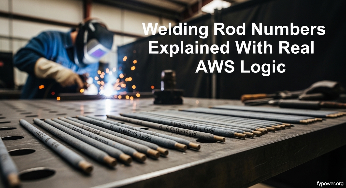
    Welding rod numbers (AWS classification) identify electrode properties for shielded metal arc welding (SMAW), commonly called stick welding. The first two digits indicate minimum tensile strength in thousands of PSI, the third digit shows welding position capability, and the last digits specify flux coating type and current characteristics. For example, an E7018 rod has 70,000 PSI tensile strength, works in all positions, and uses a low-hydrogen flux coating.

    This guide breaks down the entire AWS numbering system digit by digit, so you can read any welding rod code like a pro.

    What Is the AWS Classification System?

    The American Welding Society (AWS) created the classification system we use today under the AWS A5.1 standard for carbon steel electrodes. This system provides a universal language that welders, engineers, and manufacturers all understand. When you pick up an E7018 from Lincoln Electric, Hobart, or Forney, you know exactly what you’re getting regardless of brand.

    The prefix “E” simply stands for electrode – the technical term for what most welders call a rod or stick. Every welding rod follows this same basic format, making it easy to compare different electrodes at a glance.

    SMAW (Shielded Metal Arc Welding) is the formal name for stick welding. The flux coating on these rods creates a protective gas cloud when you strike an arc, shielding your weld from atmospheric contamination that would weaken the metal. This self-shielding capability is what makes stick welding so versatile for field work, farm repairs, and construction sites.

    How to Read Welding Rod Numbers? Step by Step

    Reading a welding rod number is like decoding a secret message. Once you understand the pattern, you can instantly identify the rod’s capabilities. Let’s break down each position using the common E7018 electrode as our example.

    Position 1-2: Tensile Strength (in thousands of PSI)

    The first two digits (or sometimes three) represent the electrode’s minimum tensile strength – how much pulling force the welded metal can withstand before breaking. This number is expressed in thousands of pounds per square inch (PSI).

    • 60 = 60,000 PSI tensile strength (mild steel applications)
    • 70 = 70,000 PSI tensile strength (structural steel)
    • 80 = 80,000 PSI tensile strength (higher strength applications)

    Definition: Tensile strength measures the maximum stress a material can withstand while being stretched or pulled before breaking. Higher tensile strength means stronger welds capable of handling heavier loads.

    For most general welding projects, 60-series rods (60,000 PSI) provide plenty of strength. Structural applications, building codes, and critical welds typically require 70-series rods (70,000 PSI). The difference in cost is minimal, but the 70-series offers significantly stronger welds.

    Position 3: Welding Position Capability

    The third digit tells you which welding positions you can use the electrode in. This is crucial because not all rods work in every position – some formulations simply won’t hold up against gravity when welding vertical or overhead.

    • 1 = All positions (flat, horizontal, vertical, overhead)
    • 2 = Flat and horizontal positions only (F, H)
    • 4 = Flat, horizontal, overhead (F, H, OH) – rare

    Position “1” electrodes are the most versatile and commonly used. They contain flux formulations that solidify quickly, preventing the molten metal from dripping out of the joint when welding overhead or vertical-up. This fast-freeze characteristic is what makes a rod work against gravity.

    Position “2” rods have heavier flux coatings and higher deposition rates but can only be used in flat or horizontal positions. Attempting to weld vertical or overhead with a position “2” rod will result in the weld metal falling out of the joint.

    Position 4-5: Flux Coating Type and Current

    The last two digits (sometimes treated as a single digit in older systems) specify the flux coating composition and the type of welding current the rod requires. This is where things get technical, as these digits indicate the specific chemical formulation of the flux.

    The flux coating does more than just shield the weld – it influences arc characteristics, penetration depth, slag removal ease, and weld appearance. Different flux formulations are optimized for different applications and power sources.

    Last DigitFlux TypeCurrent TypePenetration
    0Cellulosic (high cellulose)DCEP (DC+)Deep
    1Cellulosic (with potassium)AC or DCEPDeep
    3High titania (rutile)AC, DCEN, or DCEPLight
    4Iron powder, titaniaAC, DCEN, or DCEPMedium
    8Low-hydrogenAC, DCEN, or DCEPMedium

    Common Welding Rod Types Explained

    Now that you understand the numbering system, let’s look at the most common welding rods you’ll encounter. Each has specific characteristics that make it ideal for certain applications.

    E6010: The Deep Penetrator

    E6010 is often called the “digging rod” because its aggressive arc digs into the workpiece. This deep penetration makes it ideal for root passes on pipe welds and welding through rust, paint, or mill scale.

    • Strength: 60,000 PSI
    • Position: All positions
    • Flux: Cellulosic (high cellulose content)
    • Current: DCEP (DC+) only – will not work on AC welders
    • Penetration: Deep
    • Best For: Pipe root passes, farm equipment repair, rusty/dirty metal, open root butt welds

    The cellulosic flux coating creates a digging arc that burns through surface contaminants. This makes 6010 the go-to choice for field work where metal preparation isn’t perfect. However, the weld bead is somewhat rough and the slag is thick – this rod is about function, not cosmetics.

    Important: E6010 requires DC electrode positive (reverse polarity). It will not run on AC-only welders. Many newer inverter welders also struggle with 6010 due to its unique arc characteristics.

    E6011: The AC-Friendly Alternative

    E6011 is essentially the AC-compatible version of E6010. It offers similar deep penetration and digging characteristics but runs on both AC and DC machines.

    • Strength: 60,000 PSI
    • Position: All positions
    • Flux: Cellulosic with potassium (stabilizes AC arc)
    • Current: AC or DCEP
    • Penetration: Deep
    • Best For: Same as 6010 but for AC welder owners, general repair work

    The addition of potassium to the flux coating stabilizes the arc on alternating current. This makes 6011 the preferred deep-penetration rod for hobbyists with “buzz box” AC welders. If you have an AC-only machine, 6011 is your substitute for 6010.

    E6013: The Beginner’s Rod

    E6013 is widely considered the easiest welding rod to use. Its smooth, stable arc and forgiving nature make it perfect for beginners and thin sheet metal work.

    • Strength: 60,000 PSI
    • Position: All positions
    • Flux: High titania (rutile)
    • Current: AC, DCEN, or DCEP
    • Penetration: Light to medium
    • Best For: Beginners, sheet metal, cosmetic welds, general fabrication

    Experienced welders often say 6013 “can’t make a bad-looking weld” – the arc is so smooth and stable that it produces pretty beads even with poor technique. The light penetration prevents burn-through on thin materials. This is the rod most welding schools start students on.

    However, 6013’s light penetration can be a disadvantage on thicker materials or dirty surfaces. It’s not ideal for structural applications or heavy fabrication where deep penetration is needed.

    E7018: The Structural Standard

    E7018 is the industry standard for structural welding and code work. Its low-hydrogen flux coating produces high-quality, crack-resistant welds with excellent mechanical properties.

    • Strength: 70,000 PSI
    • Position: All positions
    • Flux: Low-hydrogen with iron powder
    • Current: AC, DCEN, or DCEP
    • Penetration: Medium
    • Best For: Structural steel, pressure vessels, heavy equipment, code-required welds

    The “low-hydrogen” designation means the flux coating contains minimal moisture-absorbing compounds. This is critical because hydrogen in the weld can cause cracking – especially in high-strength steels or restrained joints. For this reason, 7018 is required for most structural and pressure vessel applications.

    Storage warning: E7018 absorbs moisture from the air and must be kept in a rod oven at 250-300degF once the original package is opened. Wet 7018 will produce porosity and hydrogen cracking. If you’re buying 7018 for occasional use, consider hermetically sealed “low-hydrogen in a vacuum” containers.

    E7024: The Production Rod

    E7024 is designed for high deposition rates in flat and horizontal positions. Its heavy iron powder coating acts as a metal filler, allowing you to deposit more weld metal faster.

    • Strength: 70,000 PSI
    • Position: Flat and horizontal only
    • Flux: High iron powder, titania
    • Current: AC, DCEN, or DCEP
    • Penetration: Medium
    • Best For: Production welding, heavy plate, long flat welds

    The massive iron powder content (up to 50% of the coating weight) makes 7024 deposit weld metal very quickly. This is ideal for long flat welds where you need to fill a joint efficiently. The weld bead is smooth and convex, with easy slag removal.

    However, 7024’s heavy flux makes it impossible to use in vertical or overhead positions – the slag would simply drip out. Don’t attempt vertical-up welding with this rod.

    Flux Coating Types Explained

    The flux coating is what distinguishes one welding rod from another. Understanding flux types helps you predict how a rod will behave before you even strike an arc.

    Cellulosic Flux (E6010, E6011)

    Cellulosic flux contains high amounts of organic cellulose material. When the arc strikes, this cellulose combusts violently, creating a forceful digging arc and a gas shield that pushes contaminants away from the weld pool.

    • Pros: Deep penetration, burns through rust/paint, excellent for root passes
    • Cons: Heavy slag, rough weld appearance, produces significant smoke
    • Best For: Pipe welding, field repairs, dirty metal

    Rutile/Titania Flux (E6013, E7024)

    Rutile flux is based on titanium dioxide (titania). It produces a smooth, stable arc with minimal spatter and creates a visually appealing weld bead. This is the most user-friendly flux type.

    • Pros: Easy to use, smooth arc, pretty welds, low spatter
    • Cons: Light penetration, not ideal for dirty metal
    • Best For: Beginners, sheet metal, cosmetic applications

    Low-Hydrogen Flux (E7018)

    Low-hydrogen flux uses calcium carbonate and other compounds that minimize hydrogen content in the weld. This produces ductile, crack-resistant welds with excellent mechanical properties.

    • Pros: Crack-resistant, high-quality welds, code-approved
    • Cons: Requires dry storage, more difficult to restart hot rod
    • Best For: Structural welding, high-strength steel, critical applications

    Amperage Settings by Rod Size

    Setting the correct amperage for your welding rod is crucial for good weld quality. Too low and the rod will stub, too high and you’ll burn through. Here are typical amperage ranges for common rod diameters:

    Rod DiameterE6010/E6011E6013E7018
    1/16 inch (1.6mm)20-40 amps25-45 ampsN/A
    5/64 inch (2.0mm)40-70 amps45-70 amps50-80 amps
    3/32 inch (2.4mm)60-90 amps65-100 amps75-110 amps
    1/8 inch (3.2mm)80-115 amps85-140 amps100-130 amps
    5/32 inch (4.0mm)110-160 amps130-170 amps140-180 amps

    Start in the middle of the recommended range and adjust based on your arc characteristics. The sound of a properly set arc is often described as “bacon frying” – a steady crackling sound. If the rod stubs into the workpiece, increase amperage. If the arc sounds harsh and the metal melts too fast, decrease amperage.

    Rod Diameter vs Material Thickness

    Choosing the right rod diameter for your material thickness prevents burn-through on thin metal and ensures proper penetration on thick plate.

    Material ThicknessRecommended Rod Diameter
    1/16 inch (1.6mm)1/16 inch rod
    1/8 inch (3.2mm)3/32 inch rod
    3/16 inch (4.8mm)1/8 inch rod
    1/4 inch (6.4mm)1/8 inch or 5/32 inch rod
    3/8 inch (9.5mm) and thicker5/32 inch or 3/16 inch rod

    Choosing the Right Welding Rod for Your Project

    Based on common applications from welding forums and practical experience, here’s a quick reference guide:

    • Sheet metal and thin gauge: E6013 in 3/32″ diameter – light penetration prevents burn-through
    • Farm equipment repair (rusty/dirty): E6010 (DC) or E6011 (AC) – digs through contaminants
    • Structural welding: E7018 – code-required, crack-resistant welds
    • General DIY and hobby: E6013 – forgiving and easy to use
    • Pipe welding root pass: E6010 – deep penetration for open root
    • Long flat production welds: E7024 – high deposition rate
    • Vertical and overhead: E6011, E6013, or E7018 – all position rods with fast-freeze slag

    Frequently Asked Questions

    Is 6013 or 7018 stronger?

    E7018 is stronger than 6013. E7018 has a tensile strength of 70,000 PSI compared to E6013’s 60,000 PSI. The 7018 also produces more ductile, crack-resistant welds due to its low-hydrogen flux coating, making it the better choice for structural applications.

    What do the numbers on welding rods mean?

    Welding rod numbers indicate tensile strength, welding position, and flux coating type. The first two digits show minimum tensile strength in thousands of PSI (60 = 60,000 PSI). The third digit indicates position capability (1 = all positions, 2 = flat/horizontal only). The last digits specify flux coating composition and current type.

    What does 6013 welding rod mean?

    E6013 is an all-position electrode with 60,000 PSI tensile strength and a high-titania flux coating. The ’60’ indicates 60,000 PSI strength, ‘1’ means all positions, and ’13’ specifies a rutile flux that runs smoothly on AC or DC. It’s known as the beginner’s rod due to its forgiving arc and light penetration.

    What is 1G, 2G, 3G, 4G, 5G, 6G welding?

    These are welding position certification codes. 1G = flat groove weld, 2G = horizontal groove weld, 3G = vertical groove weld, 4G = overhead groove weld, 5G = horizontal fixed pipe weld, and 6G = 45-degree inclined pipe weld (the most difficult). The ‘G’ stands for groove weld, while ‘F’ would indicate fillet weld positions.

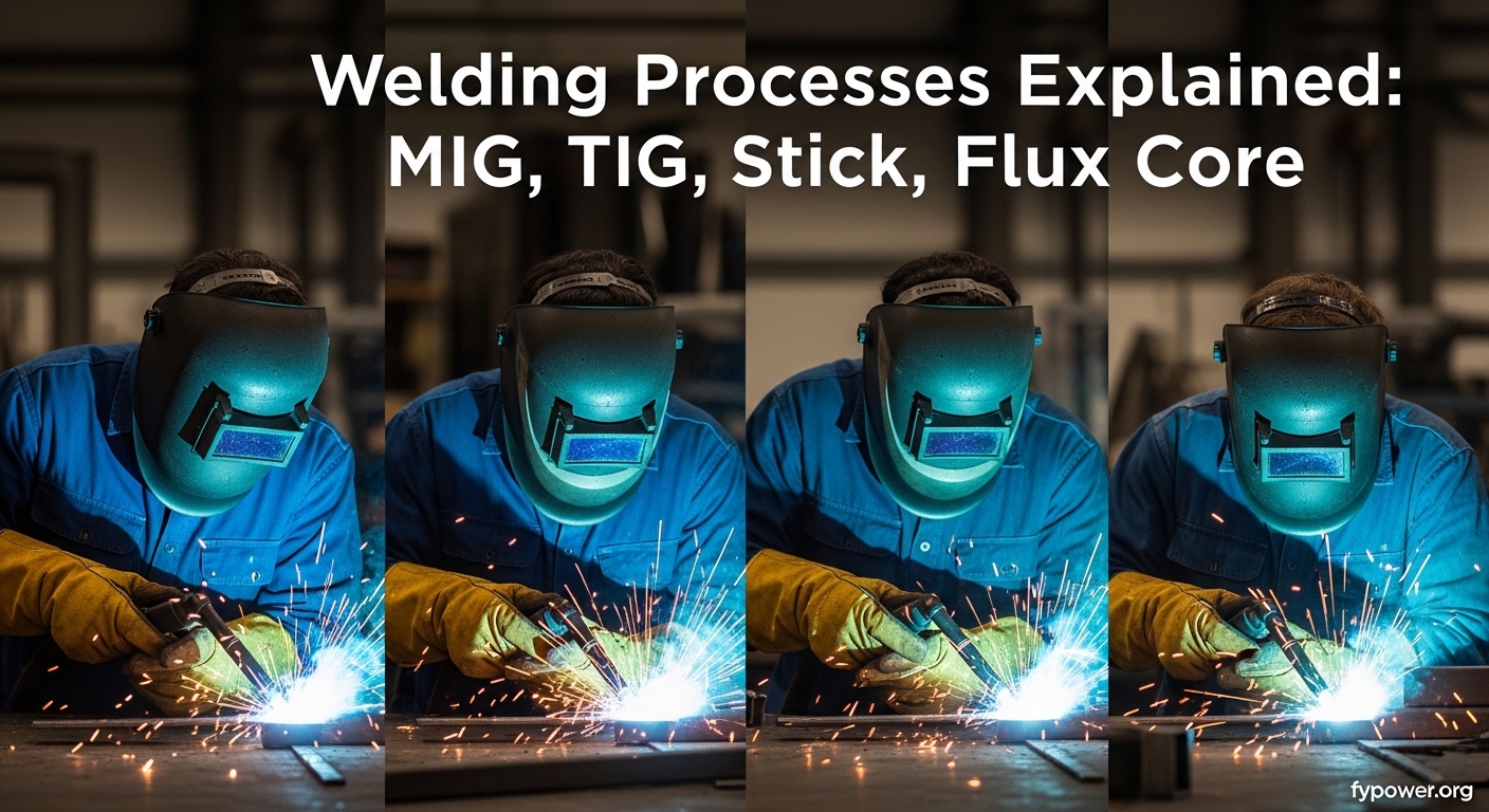
  • Welding Processes Explained: MIG, TIG, Stick, and Flux Core Compared

    Welding Processes Explained: MIG, TIG, Stick, and Flux Core Compared

    Welding is the process of joining separate metal pieces by melting and fusing them together using heat, pressure, or both to create a strong permanent bond. This fundamental metalworking skill builds everything from skyscrapers to exhaust pipes.

    When I started welding 15 years ago, I was overwhelmed by the different options available. After working with fabricators who’ve built everything from race car frames to farm equipment, I’ve learned that choosing the right process makes all the difference.

    Each welding process has distinct advantages, limitations, and ideal applications. The right choice depends on your skill level, the materials you’re working with, your budget, and where you’ll be welding.

    Understanding How Welding Works

    Welding works by creating an electric arc between an electrode and the base metal, generating temperatures up to 6,000 degrees Fahrenheit that melts the metal. Filler material is added to fill gaps, and as the metal cools, it forms a single, unified piece.

    Welding: The process of joining separate metal pieces by melting and fusing them together using heat, pressure, or both to create a strong permanent bond. Unlike mechanical fasteners like bolts or rivets, welding creates a continuous metal connection that can be as strong as or stronger than the base material.

    The electric arc that makes welding possible is essentially controlled lightning. By directing this intense heat through a focused point, welding processes can melt and fuse metals with precision that would be impossible with other joining methods.

    After spending time in fabrication shops across 2026, I’ve seen how this simple principle – controlled heat melting metal – can transform raw materials into functional structures. The key difference between welding processes lies in how they create and maintain that arc, and how they protect the molten metal from contamination.

    Basic Welding Components

    Every arc welding process shares four essential components. The power source provides the electricity needed to create the arc. The electrode delivers the current to the workpiece and may also add filler metal. Shielding protects the molten weld pool from atmospheric contamination. The ground clamp completes the electrical circuit.

    Understanding these basics helps demystify welding. Once you realize that all these processes are variations on the same theme, choosing between them becomes much easier.

    The Four Main Welding Processes at a Glance

    Quick Overview: MIG welding is the most beginner-friendly and widely used. TIG produces the cleanest welds but has the steepest learning curve. Stick welding is the go-to for outdoor and heavy-duty work. Flux core offers a no-gas alternative to MIG with similar speed.

    1. MIG Welding (GMAW) – Uses a wire feed electrode and shielding gas. Easiest to learn and most versatile for thin to medium thickness metals.
    2. TIG Welding (GTAW) – Uses a non-consumable tungsten electrode and filler rod. Produces the highest quality welds but has the steepest learning curve.
    3. Stick Welding (SMAW) – Uses a consumable electrode coated in flux. Works outdoors in wind and on rusty or dirty metal.
    4. Flux Cored Welding (FCAW) – Uses a tubular wire with flux core. No external gas needed for self-shielded versions, great for outdoor work.

    MIG Welding (GMAW) – The Most Common Process

    Gas Metal Arc Welding (GMAW), commonly called MIG welding, is the most widely used welding process in 2026. MIG stands for Metal Inert Gas, referring to the shielding gas that protects the weld pool from contamination.

    How MIG Welding Works?

    MIG welding uses a continuously fed wire electrode that serves as both filler metal and conductor. An electric arc forms between the wire and the base metal, generating temperatures up to 6,000 degrees Fahrenheit. The arc melts the base metal and the wire, creating a puddle that fuses as it cools.

    Simultaneously, shielding gas flows through the welding torch, displacing air and preventing oxidation and porosity in the weld. The most common gas mix is 75% argon and 25% carbon dioxide for steel welding.

    I’ve seen MIG welders complete production welding tasks 3-4 times faster than other methods. The continuous wire feed means you don’t stop to change electrodes, making it ideal for long welds and high-production environments.

    Arc: The electrical discharge that occurs between the electrode and workpiece, generating the intense heat needed to melt metal. Arc welding processes create temperatures from 3,000 to over 10,000 degrees Fahrenheit depending on the process.

    Equipment Needed for MIG Welding

    Basic MIG Setup Checklist

    • MIG welder with wire drive system ($400-$3,000)
    • Shielding gas cylinder (C25 mix for steel: 75% argon, 25% CO2)
    • Welding wire appropriate to your material (ER70S-6 for steel)
    • Ground clamp and work cable
    • MIG gun/torch assembly
    • Welding helmet (auto-darkening recommended)
    • Protective gloves and jacket

    When to Use MIG Welding

    MIG excels at welding mild steel from 24 gauge to 1/2 inch thick. It’s the go-to choice for automotive bodywork, exhaust systems, light fabrication, and DIY projects. The process produces clean welds with minimal spatter and excellent appearance.

    After helping a local fabricator set up his shop in 2026, we chose MIG as the primary process because it handles 80% of general fabrication needs. The learning curve is shallow enough that new hires become productive within a week.

    Skill Difficulty: EASIEST TO LEARN – Most beginners produce acceptable welds within 2-3 hours of practice. The wire feeder maintains consistent arc length, reducing one major variable.

    MIG Welding Pros and Cons

    MIG Welding Assessment

    Beginner Friendliness
    9.5/10

    Weld Speed
    9.0/10

    Outdoor Capability
    3.0/10

    Pros:

    • Easiest process to learn – most people weld competently in a day
    • Fast deposition rate – excellent for production work
    • Clean welds with minimal spatter
    • No slag to chip away after welding
    • Can weld thin materials without burn-through
    • Versatile – works on steel, stainless, and aluminum

    Cons:

    • Requires shielding gas – wind will blow it away
    • Equipment is more expensive than stick
    • Wire feed system requires maintenance
    • Not ideal for thick structural steel over 1/2 inch
    • Requires clean metal – won’t work well on rusty or painted surfaces

    TIG Welding (GTAW) – Precision and Control

    Gas Tungsten Arc Welding (GTAW), known as TIG welding, produces the highest quality welds of any process. The precision and control available with TIG make it the preferred choice for aerospace, motorsports, and artistic metalwork.

    How TIG Welding Works?

    TIG welding uses a non-consumable tungsten electrode to create the arc. Unlike other processes, the filler metal is added separately by hand using a filler rod. This gives the welder independent control over the arc and the filler material.

    The tungsten electrode doesn’t melt – it maintains a stable arc while the welder feeds filler rod into the weld puddle with their off-hand. Shielding gas (typically pure argon) protects the weld area from contamination.

    Tungsten: An extremely hard, heat-resistant metal with the highest melting point of any pure metal (6,192 degrees Fahrenheit). Tungsten electrodes don’t melt during welding, making them ideal for TIG’s non-consumable electrode design.

    I’ve watched master fabricators build trophy-truck frames using TIG exclusively. The ability to make precise, controlled welds on thin tubing while maintaining full penetration is something only TIG can do consistently.

    Equipment Needed for TIG Welding

    Basic TIG Setup Checklist

    • TIG welder with high-frequency start ($800-$5,000)
    • TIG torch with gas lens kit
    • Tungsten electrodes (2% thoriated or lanthanated for steel)
    • Pure argon gas cylinder
    • Filler rods (material-specific)
    • Foot pedal or finger control for amperage
    • High-quality welding helmet

    When to Use TIG Welding

    TIG excels on materials thinner than 1/8 inch and on metals requiring high-quality appearance. It’s the standard for stainless steel food processing equipment, aluminum aircraft components, and critical structural welds where appearance matters.

    In a shop I worked with in 2026, we used TIG exclusively for exhaust systems on high-performance cars. The ability to control heat input precisely prevented warping thin stainless tubing while producing beautiful, consistent welds.

    Skill Difficulty: HARDEST TO MASTER Most welders need 3-6 months of regular practice to achieve competence. You’re controlling torch angle, arc length, filler rod feeding, and foot pedal simultaneously – that’s four independent movements.

    TIG Welding Pros and Cons

    TIG Welding Assessment

    Weld Quality
    10/10

    Beginner Friendliness
    2.0/10

    Material Versatility
    9.5/10

    Pros:

    • Highest quality, cleanest welds possible
    • Full control over heat input – perfect for thin materials
    • Can weld virtually any metal including exotic alloys
    • No spatter – minimal post-weld cleanup
    • Precise control for intricate and artistic work
    • Can weld without filler metal for autogenous welds

    Cons:

    • Steepest learning curve – takes significant practice
    • Slowest process – not suited for production work
    • Most expensive equipment setup
    • Requires very clean metal surface
    • Difficult to use outdoors or in drafts
    • Requires both hands and foot control simultaneously

    Stick Welding (SMAW) – Rugged and Versatile

    Shielded Metal Arc Welding (SMAW), commonly called Stick welding, is the oldest and most versatile arc welding process. Despite being invented in the late 1800s, Stick remains essential for construction, farm repair, and field work.

    How Stick Welding Works?

    Stick welding uses a consumable electrode rod coated in flux. When you strike an arc by scratching the electrode against the workpiece, the flux coating melts and creates a shielding gas cloud while also forming slag that protects the cooling weld.

    As the electrode burns away, it becomes shorter and the welder must maintain proper arc length by feeding the electrode into the work manually. This constant adjustment is the primary skill challenge in Stick welding.

    Flux: A chemical coating on Stick welding electrodes that vaporizes to create shielding gas. The remaining flux forms slag that protects the cooling weld from atmospheric contamination. Slag must be chipped away after welding.

    I’ve used Stick welding on farm equipment repairs where nothing else would work. The ability to weld rusty, painted steel in the middle of a field with nothing but a generator-powered welder is unmatched by any other process.

    Equipment Needed for Stick Welding

    Basic Stick Setup Checklist

    • Stick welder (AC/DC capable recommended) ($200-$1,500)
    • Electrode holder (stinger)
    • Ground clamp
    • Various Stick electrodes (E6010, E6011, E7018 most common)
    • Electrode oven for storage (optional but recommended)
    • Chipping hammer and wire brush
    • Welding helmet and protective gear

    When to Use Stick Welding?

    Stick welding dominates in construction, pipeline work, shipbuilding, and farm repair. The process handles thick structural steel, cast iron, and works in conditions that would be impossible for MIG or TIG.

    After a storm damaged fencing on a property in 2026, I repaired 200 feet of heavy steel fencing using a Stick welder powered by a portable generator. The wind was blowing 20 mph – MIG would have been completely impossible.

    Skill Difficulty: MODERATE – Easier than TIG but harder than MIG. Most people learn basic Stick welding in 1-2 weeks. The challenge is maintaining consistent arc length as the electrode burns down.

    Stick Welding Pros and Cons

    Stick Welding Assessment

    Outdoor Capability
    10/10

    Forgiving on Dirty Metal
    9.0/10

    Weld Appearance
    5.0/10

    Pros:

    • Works outdoors in wind – no shielding gas to blow away
    • Forgives rusty, dirty, or painted metal surfaces
    • Simplest equipment – least expensive to get started
    • Can weld very thick materials
    • Portable – works with generator power
    • No gas cylinders required

    Cons:

    • Produces slag that must be chipped away
    • More spatter than MIG or TIG
    • Electrodes are consumable – frequent changes needed
    • Lower efficiency – about 60% of electrode becomes weld metal
    • Not suitable for thin materials under 1/8 inch
    • Requires frequent electrode replacement during long welds

    Flux Cored Arc Welding (FCAW) – No Gas Required

    Flux Cored Arc Welding bridges the gap between MIG and Stick welding. It uses a continuously fed tubular wire filled with flux, combining the speed of wire feed with the versatility of flux shielding.

    How Flux Core Welding Works?

    FCAW uses a hollow wire electrode filled with flux materials. When the arc forms, the flux vaporizes to create shielding gas and forms slag protection similar to Stick welding. This gives FCAW two distinct varieties: self-shielded (no gas) and gas-shielded (with external CO2).

    Self-shielded FCAW is particularly popular because it requires no external gas cylinder. The flux core provides all the shielding needed, making it ideal for outdoor work and field repairs.

    I’ve seen FCAW become the standard for farm equipment repair in 2026. Farmers can weld in open fields, on rusty equipment, without worrying about wind blowing away their shielding gas or hauling heavy cylinders.

    Equipment Needed for Flux Core Welding

    Basic Flux Core Setup Checklist

    • MIG welder capable of FCAW (most are) ($400-$2,000)
    • Flux cored wire (E71T-11 for general purpose)
    • Optional: CO2 cylinder for gas-shielded FCAW
    • Ground clamp and work cable
    • Welding helmet and protective gear
    • Chipping hammer and wire brush (for slag removal)

    When to Use Flux Core Welding?

    Flux core excels at heavy fabrication, shipbuilding, and outdoor construction. The process penetrates deeper than MIG and handles thicker materials more effectively. Self-shielded FCAW is the go-to choice for field work and remote locations.

    Skill Difficulty: EASY TO MODERATE – Similar learning curve to MIG welding. If you can MIG weld, you can transition to flux core with minimal practice. The continuous wire feed maintains consistent arc length.

    Flux Core Welding Pros and Cons

    Flux Core Assessment

    Outdoor Capability
    9.0/10

    Penetration Depth
    9.0/10

    Weld Appearance
    6.0/10

    Pros:

    • No shielding gas needed (self-shielded version)
    • Works well outdoors and in wind
    • Deeper penetration than MIG
    • Handles dirty metal better than MIG
    • Continuous wire feed – fast like MIG
    • Excellent for thick materials

    Cons:

    • Produces slag that must be removed
    • More spatter than solid wire MIG
    • Wire is more expensive than solid MIG wire
    • Not ideal for thin materials
    • Less clean appearance than MIG or TIG
    • Fume production is higher than MIG

    Welding Process Comparison Table

    Process Difficulty Outdoor Use Min Thickness Max Thickness Startup Cost Weld Speed
    MIG (GMAW) Easy Poor 24 ga 1/2 inch $$ Fast
    TIG (GTAW) Hard Poor Thin 1/4 inch $$$ Slow
    Stick (SMAW) Moderate Excellent 1/8 inch Unlimited $ Moderate
    Flux Core (FCAW) Easy Good 1/8 inch 1 inch+ $$ Fast

    Which Process for Which Metal?

    Different metals have specific welding requirements based on their thermal conductivity, melting point, and oxide characteristics. Choosing the wrong process for your material can lead to weak welds, warping, or complete failure.

    Material MIG TIG Stick Flux Core Best Choice
    Mild Steel Excellent Excellent Excellent Excellent MIG
    Stainless Steel Good Excellent Fair Fair TIG
    Aluminum Good* Excellent Poor Poor TIG
    Cast Iron Poor Fair Good** Fair Stick
    Exotic Alloys Fair Excellent Poor Poor TIG

    *Requires spool gun and pure argon gas
    **Requires special nickel electrodes and pre-heating

    Other Welding Processes

    While MIG, TIG, Stick, and Flux Core represent the vast majority of welding done today, several specialized processes deserve mention for specific applications.

    Plasma Arc Welding (PAW)

    Plasma arc welding uses a constricted arc that creates a plasma jet of extremely high temperature. This process offers greater precision and deeper penetration than TIG, making it ideal for aerospace and high-tech applications. The equipment cost and complexity limit PAW to specialized industrial uses.

    Oxy-Fuel Welding (OFW)

    Oxy-fuel welding uses a combination of oxygen and fuel gas (typically acetylene) to create a flame hot enough to melt metal. Unlike electric arc processes, oxy-fuel doesn’t require electricity. It remains valuable for brazing, cutting, and welding thick steel plates. However, oxy-fuel produces a large heat-affected zone and less precise control than arc welding methods.

    Resistance Welding

    Resistance welding includes spot welding and seam welding. The process uses electrical resistance to generate heat at the joint point, combined with pressure to fuse the metals. No filler material is used. Resistance welding is the standard in automotive manufacturing for joining sheet metal components, but the specialized equipment limits it to production environments.

    Laser and Electron Beam Welding

    These high-tech processes use focused energy beams to create extremely precise, deep-penetration welds with minimal heat input. Laser welding is becoming more common in automotive and medical device manufacturing. Electron beam welding requires a vacuum chamber and is used for critical aerospace components. Both require substantial investment and specialized training.

    Welding Safety Essentials

    All welding processes share common hazards but have specific safety considerations. After 15 years in metalworking, I’ve seen enough preventable injuries to know that safety isn’t optional.

    WARNING: Welding produces UV radiation that can damage your eyes in seconds – never look at an arc without proper protection. All processes require appropriate personal protective equipment (PPE) and ventilation.

    Common Safety Equipment (All Processes)

    • Auto-darkening welding helmet (minimum shade 10)
    • Flame-resistant welding jacket or leather apron
    • Welding gloves (specific to your process)
    • Steel-toed leather boots
    • Respirator when welding in confined spaces

    Process-Specific Safety Considerations

    MIG/TIG Safety: These processes use compressed gas cylinders. Secure cylinders upright and chain them to a wall or cart. A falling cylinder can become a projectile that penetrates concrete walls. Argon is an asphyxiant – never weld in confined spaces without ventilation.

    Stick Safety: Stick welding produces the most UV radiation of any process. Use a hood with at least shade 10, and consider shade 11-12 for high-amperage work. The flux coating can contain hazardous materials – always wash your hands after handling electrodes.

    Flux Core Safety: Self-shielded FCAW produces significant fumes. The flux core vaporizes and creates metallic fumes that you shouldn’t breathe. Use respiratory protection and ensure cross-ventilation when welding indoors or in semi-enclosed spaces.

    Fire Prevention

    Welding spatter can travel 20 feet or more. Always clear a 35-foot radius of flammable materials before welding. Keep a fire extinguisher rated for electrical fires (Class ABC) within 10 feet of your work area. Never weld on or near containers that have held flammable materials, even if they appear empty – vapors can remain explosive.

    Which Welding Process Should You Choose?

    Choosing the right welding process depends on several factors. After helping dozens of beginners set up their first welder in 2026, I’ve developed a simple decision framework.

    Process Selection Guide

    Choose MIG if you:

    • Are a complete beginner
    • Weld indoors in a shop or garage
    • Work mostly with mild steel under 1/2 inch thick
    • Want clean-looking welds with minimal cleanup
    • Have a budget of $500-1,500

    Choose TIG if you:

    • Value weld quality over speed
    • Work with thin materials or exotic metals
    • Need precision for artistic or show-quality work
    • Have time to develop the skill
    • Can invest $1,000-3,000 in equipment

    Choose Stick if you:

    • Weld outdoors or in drafty conditions
    • Work with rusty, dirty, or painted metal
    • Need a portable, simple setup
    • Weld thick structural materials
    • Have a limited budget ($200-600)

    Choose Flux Core if you:

    • Want MIG speed without gas hassles
    • Weld outdoors or in windy conditions
    • Work with thicker materials
    • Already have a MIG welder that can run flux wire

    My Recommendation for Beginners

    For most beginners, I recommend starting with MIG welding. The learning curve is gentle, and you’ll produce decent welds quickly. A 140-amp MIG welder will handle 90% of home and hobby projects. Once you’ve mastered MIG, you can expand into other processes as needed.

    If you’re on a tight budget or know you’ll be welding outdoors, a basic Stick welder is the most economical starting point. You’ll develop fundamental welding skills that transfer to other processes, and Stick welders hold their resale value well.

    Frequently Asked Questions

    What are the 4 main types of welding?

    The four main types of welding are MIG (GMAW), TIG (GTAW), Stick (SMAW), and Flux Cored (FCAW). MIG uses a wire feed with shielding gas and is the easiest to learn. TIG provides the highest quality welds but requires significant skill. Stick welding works best outdoors on dirty metal. Flux core combines wire feed speed with self-shielding flux for portability.

    Which welding process is easiest to learn?

    MIG welding is the easiest process to learn. Most beginners produce acceptable welds within 2-3 hours of practice. The continuous wire feed maintains consistent arc length automatically, eliminating one major variable that makes other processes difficult. MIG welders are also the most forgiving of mistakes.

    What is the most common welding process?

    MIG welding is the most common welding process in 2026 for manufacturing, automotive, and DIY applications. Its ease of use, speed, and versatility make it the default choice for most fabrication shops. The automotive industry relies heavily on MIG for production welding due to its speed and consistency.

    What is the difference between MIG and TIG welding?

    MIG uses a continuously fed wire that serves as both electrode and filler, while TIG uses a fixed tungsten electrode with separately added filler rod. MIG is faster and easier to learn but produces lower quality welds. TIG is slower and harder to master but produces the cleanest, highest quality welds possible. MIG works best on production work, while TIG excels at precision and show-quality work.

    What welding process should a beginner start with?

    Beginners should start with MIG welding if they have the budget and will be welding indoors. The learning curve is gentle and you will see results quickly. If you have a limited budget or know you will be welding outdoors, start with Stick welding. It builds fundamental skills and works in conditions that defeat MIG. Most professional welders learn Stick first because it teaches the fundamentals.

    Can different metals be welded together?

    Yes, different metals can be welded together using special filler metals and techniques, called dissimilar welding. However, some combinations are problematic. Steel to stainless steel works well with the correct filler. Aluminum to steel requires special bimetallic inserts or specialized processes like friction welding. Always consult a welding compatibility chart before attempting dissimilar metal welds.

    Which is stronger MIG or TIG welding?

    When properly executed, both MIG and TIG welds can be stronger than the base metal. TIG typically produces stronger welds on thin materials and critical applications because of the precise control and lack of heat-affected zone issues. For most practical purposes on mild steel, a properly done MIG weld will be as strong as a TIG weld. The welder’s skill matters more than the process.

    What type of welding is used for exhaust pipes?

    TIG welding is the preferred choice for exhaust systems, especially stainless steel and high-performance applications. TIG provides the clean, beautiful welds desired on visible exhaust components and allows precise heat control to prevent warping thin tubing. MIG can be used for exhaust work on thicker steel or where appearance isn’t critical, but TIG dominates the performance exhaust market.

  • Welding Flames: 3 Types, Temperatures & How to Adjust Your Torch

    Welding Flames: 3 Types, Temperatures & How to Adjust Your Torch

    What Are Welding Flames?

    Welding flames are high-temperature flames produced by gas welding torches, primarily oxy-acetylene systems, used to melt and fuse metals during welding operations. These flames generate extreme heat reaching up to 6,300degF, allowing welders to join metal pieces through controlled fusion.

    Understanding welding flames is essential because the flame type directly affects weld quality. Each flame produces different chemical effects on molten metal, some adding carbon, some adding oxygen, while others remain chemically neutral. Using the wrong flame can cause brittle, porous, or chemically compromised welds that fail under stress.

    I learned this lesson the hard way when I first started welding. Using a carburizing flame on mild steel created a brittle joint that cracked within days. After 15 years in metal fabrication, I have seen how proper flame selection makes or breaks a weld.

    Three Types of Welding Flames: Quick Reference

    Quick Summary: Gas welding uses three flame types. Neutral flame has balanced gases and is used for most welding. Carburizing flame has excess fuel and adds carbon to metal. Oxidizing flame has excess oxygen and is used for specific metals like copper and brass.

    The three types of welding flames are determined by the ratio of oxygen to fuel gas in your torch. Here is a comprehensive comparison:

    Flame TypeOxygen RatioTemperatureVisual SignsBest Applications
    NeutralBalanced (1:1)5,850degF (3,232degC)Clear inner cone, no featherMild steel, stainless steel, most general welding
    CarburizingExcess fuel5,700degF (3,149degC)Acetylene feather extends beyond inner coneHard surfacing, alloy steel, adding carbon to metal
    OxidizingExcess oxygen6,300degF (3,482degC)Shorter inner cone, pointed tip, hissing soundCopper, brass, bronze, cast iron welding

    Complete Combustion: The ideal burning condition where all fuel gas combines perfectly with oxygen, producing maximum heat and cleanest flame with minimal soot or chemical byproducts.

    Neutral Flame: The Balanced Standard

    The neutral flame is the most commonly used welding flame in oxy-acetylene welding. It represents the perfect balance between oxygen and acetylene gases, achieving complete combustion. When I teach welding students, this is the first flame type they master because it serves as the foundation for all other flame adjustments.

    A neutral flame produces a clearly defined inner cone surrounded by a lighter outer envelope. The inner cone appears sharp and distinct, typically bluish-white in color. No “acetylene feather” should extend beyond this inner cone, which indicates excess fuel.

    Temperature
    5,850degF
    Gas Ratio
    1:1 Balanced
    Inner Cone
    Sharp & Clear
    Chemical Effect
    Neutral

    At approximately 5,850degF (3,232degC), the neutral flame provides sufficient heat for most welding applications without introducing unwanted chemical changes to the metal. The flame zones include a hot inner cone where combustion occurs, an intermediate zone with reducing conditions, and an outer envelope where secondary combustion happens with atmospheric oxygen.

    Neutral flames are ideal for welding mild steel, stainless steel, cast iron, and most common metals. I use neutral flame for about 80% of my welding work because it produces clean, strong welds without altering the metal chemistry. According to AWS guidelines, neutral flame should be the default starting point for any oxy-fuel welding operation.

    When to Use Neutral Flame?

    • Mild Steel Welding: The standard choice for carbon steel fabrication
    • Stainless Steel: Prevents oxidation and maintains corrosion resistance
    • Cast Iron: Provides controlled heat without excessive carbon absorption
    • General Fabrication: The go-to flame for most welding applications
    • Brazing: Creates clean joints when proper filler rod is used
    Mild Steel
    Stainless Steel
    Cast Iron
    Brazing

    Carburizing Flame: When You Need Excess Fuel

    A carburizing flame contains more acetylene than oxygen, creating a fuel-rich environment. The telltale sign of a carburizing flame is the “acetylene feather” that extends beyond the inner cone. This feathery extension appears between the inner cone and outer envelope, ranging from slight (1-2x inner cone length) to excessive (3x or more).

    Carburizing flames operate at slightly lower temperatures, around 5,700degF (3,149degC). The excess acetylene does not burn completely in the inner cone, creating a reducing atmosphere that adds carbon to the molten metal. This carbon absorption can be beneficial or harmful depending on your application.

    Acetylene Feather: The visible extension of unburned acetylene beyond the inner cone in a carburizing flame. The length of this feather indicates the degree of excess fuel, ranging from a slight extension to a large, bushy flame.

    I use carburizing flame selectively for hard surfacing applications where adding carbon to the metal surface increases hardness. This technique works well when building up worn surfaces or creating wear-resistant layers on steel parts. The added carbon forms iron carbide, creating a harder surface that resists abrasion.

    Carburizing Flame Applications

    • Hard Surfacing: Adds carbon to create wear-resistant surfaces
    • High-Carbon Steel: Used on metals that already contain high carbon content
    • Alloy Steel Welding: Certain alloys benefit from reducing atmosphere
    • Flame Hardening: Creates case-hardened surface layers

    Risks of Carburizing Flame

    Using carburizing flame on the wrong metals causes problems. The excess carbon can make welds brittle and prone to cracking. I have seen failed welds where carburizing flame was used on mild steel, creating a joint that looked good initially but failed under stress due to carbon embrittlement.

    Excessive carburizing causes the metal to foam and spark during welding, indicating carbon absorption. This foaming creates porosity in the finished weld, significantly reducing strength. For most general welding applications, carburizing flame should be avoided unless you specifically need to add carbon to the metal.

    Oxidizing Flame: The Hottest Option

    The oxidizing flame contains more oxygen than fuel, making it the hottest of all welding flames at approximately 6,300degF (3,482degC). This flame type has a shorter, more pointed inner cone and produces a distinctive hissing sound when operating. The excess oxygen creates an oxidizing atmosphere that affects the metal chemistry.

    Despite being the hottest, oxidizing flame is used less frequently than neutral flame because the excess oxygen can oxidize and weaken many metals. However, for specific applications, particularly non-ferrous metals, the oxidizing flame performs exceptionally well.

    When to Use Oxidizing Flame?

    • Copper and Copper Alloys: Helps clean oxides from the metal surface
    • Brass and Bronze: Prevents zinc from vaporizing (reduces fuming)
    • Cast Iron: Some cast iron welding benefits from oxidizing conditions
    • Welding Zinc-Based Metals: Reduces zinc loss through vaporization
    Copper
    Brass
    Bronze
    Cast Iron

    I use oxidizing flame when working with copper pipe and brass fittings. The extra oxygen actually helps by burning away impurities and creating a cleaner weld pool. However, for steel welding, oxidizing flame generally creates problems rather than solutions.

    Risks of Oxidizing Flame

    The oxidizing flame causes excessive oxidation in steel welds, creating a brittle, porous joint. The excess oxygen combines with carbon in the steel, reducing carbon content at the weld zone. This decarburization weakens the metal and creates a poor-quality weld that fails under load.

    How to Adjust Welding Torch Flames: Step-by-Step?

    Quick Summary: Adjust your welding flame by starting with both valves closed, opening acetylene first to light, then adjusting oxygen to achieve neutral flame. From neutral, add acetylene for carburizing or add oxygen for oxidizing flame.

    Pre-Lighting Checklist

    • Check that oxygen and acetylene cylinder valves are closed
    • Verify regulator pressures are set correctly (typically 40-50 PSI for oxygen, 5-10 PSI for acetylene)
    • Inspect hoses for cracks or wear
    • Ensure torch valves are completely closed
    • Confirm tip size matches your welding application
    • Clear the work area of flammable materials

    Step 1: Lighting the Torch

    1. Open the acetylene valve on the torch approximately 1/4 turn
    2. Light the torch with a striker (never use a lighter or matches)
    3. Adjust the acetylene valve until the flame leaves the tip slightly, then reduce until the flame just touches the tip
    4. The flame should produce black smoke initially, which clears as you adjust

    Step 2: Adding Oxygen

    1. Slowly open the oxygen valve on the torch
    2. Watch as the inner cone forms and becomes sharper
    3. Continue adding oxygen until the acetylene feather just disappears
    4. This is your neutral flame setting

    Step 3: Achieving Neutral Flame

    A properly adjusted neutral flame has a clearly defined inner cone with no feather extending beyond it. The inner cone should appear sharp and distinct, surrounded by a lighter outer envelope. No black smoke should be present, and the flame should burn cleanly without popping or sputtering.

    Step 4: Creating Carburizing Flame

    Starting from neutral, slowly open the acetylene valve. The acetylene feather will begin to extend beyond the inner cone. For slight carburizing, extend the feather 1-2 times the inner cone length. For heavy carburizing (rarely needed), the feather can extend 3 times or more.

    Step 5: Creating Oxidizing Flame

    Starting from neutral, slowly open the oxygen valve. The inner cone will become shorter and more pointed. The flame may produce a hissing sound. Be cautious not to add excessive oxygen, which can blow out the flame or create an unstable condition.

    Flame Identification Guide

    Neutral Flame
    Inner cone clear and sharp | No feather | No hissing | Blue-white inner cone

    Carburizing Flame
    Acetylene feather visible | Feather extends beyond inner cone | Smoky if excessive | Lower temperature

    Oxidizing Flame
    Short, pointed inner cone | Hissing sound | Highest temperature | Louder than neutral

    Safety and Troubleshooting

    Safety Precautions for Oxy-Fuel Welding

    • Eye Protection: Always wear shaded safety glasses designed for gas welding (typically #3-5 shade)
    • Flame-Resistant Clothing: Wear leather welding gloves and apron to protect from UV radiation and sparks
    • Ventilation: Ensure adequate airflow to remove fumes, especially when welding metals that produce toxic vapors
    • Flashback Protection: Keep flashback arrestors installed on both oxygen and acetylene lines
    • Cylinder Security: Secure oxygen and acetylene cylinders upright and chain them to prevent tipping
    • Check for Leaks: Use soapy water solution to check all connections before lighting torch

    Common Flame Problems and Solutions

    ProblemPossible CauseSolution
    Flame pops or backfiresIncorrect pressure settings or dirty tipCheck regulator pressures, clean torch tip with proper tip cleaner
    Flame won’t lightNo gas flow or incorrect valve orderOpen acetylene first, check cylinder valves, verify gas supply
    Excessive black smokeToo much acetylene (heavy carburizing)Reduce acetylene flow, adjust toward neutral flame
    Flame is unstable or blows outExcessive oxygen or wrong tip sizeReduce oxygen flow, verify tip matches application
    Weld is porousWrong flame type for metalUse neutral flame for steel, check metal compatibility

    Beginner Mistakes to Avoid

    • Not Starting from Neutral: Always begin with neutral flame and adjust from there
    • Ignoring Visual Cues: The acetylene feather and inner cone shape tell you everything
    • Using Wrong Flame for Metal: Neutral works for most steel, carburizing for hard surfacing, oxidizing for copper alloys
    • Skipping Equipment Checks: Leaking connections can cause dangerous flashbacks
    • Adjusting While Welding: Set your flame before starting the weld, not during

    Frequently Asked Questions

    What are the three types of welding flames?

    The three types of welding flames are neutral (balanced oxygen and fuel), carburizing (excess fuel/acetylene), and oxidizing (excess oxygen). Neutral flame is used for most welding applications. Carburizing flame adds carbon to metal and is used for hard surfacing. Oxidizing flame is the hottest and is used for welding copper, brass, and bronze.

    Which flame is the hottest in welding?

    The oxidizing flame is the hottest in welding, reaching approximately 6,300degF (3,482degC). This flame has excess oxygen which creates a shorter, pointed inner cone and produces a characteristic hissing sound. The extra oxygen makes it hotter than the neutral flame (5,850degF) or carburizing flame (5,700degF).

    How do you identify a neutral flame?

    A neutral flame is identified by its clearly defined inner cone with no acetylene feather extending beyond it. The inner cone appears sharp, bluish-white, and distinct. No black smoke should be visible, and the flame should burn cleanly without popping or sputtering. The neutral flame represents a perfect 1:1 balance of oxygen to acetylene.

    What is carburizing flame used for?

    Carburizing flame is primarily used for hard surfacing applications where adding carbon to the metal surface increases hardness and wear resistance. It is also used on high-carbon steels and certain alloy steels that benefit from the reducing atmosphere. The excess acetylene creates an acetylene feather beyond the inner cone, indicating the fuel-rich condition.

    When should you use an oxidizing flame?

    Oxidizing flame should be used when welding copper, brass, bronze, and certain cast iron applications. The excess oxygen helps clean oxides from copper-based metals and prevents zinc from vaporizing in brass and bronze. However, oxidizing flame should generally be avoided for steel welding as it can cause oxidation and weak, brittle welds.

    What is the temperature of a neutral welding flame?

    A neutral oxy-acetylene welding flame reaches approximately 5,850degF (3,232degC). This temperature is sufficient for melting and welding most common metals including steel, stainless steel, and cast iron. The neutral flame provides complete combustion of the fuel gas, creating a chemically balanced welding environment.

  • Thermit Welding: Complete Guide to Process

    Thermit Welding: Complete Guide to Process

    Have you ever wondered how railway rails are joined in remote locations where electricity isn’t available? Or how electrical contractors create permanent, corrosion-resistant connections for critical grounding systems? Thermit welding provides the solution.

    Thermit welding is a fusion welding process that uses an exothermic chemical reaction between aluminum powder and iron oxide to generate intense heat for joining metals. Reaching temperatures up to 2,200 degrees Celsius without external power, this process creates permanent molecular bonds that are as strong as or stronger than the base metal itself.

    What makes thermit welding unique is its ability to work anywhere, anytime. No power grid, no gas cylinders, no complicated equipment. Just a chemical reaction that produces molten metal on demand. I’ve seen this process used in everything from high-speed rail construction to lightning protection systems, and the results are consistently impressive.

    The process was invented in 1895 by German chemist Hans Goldschmidt, who discovered that aluminum could reduce metal oxides while releasing tremendous heat. Within a few years, railway companies across Europe were using his invention to create continuous welded rail. The technology came to America in 1904, when the Holyoke Street Railway in Massachusetts became the first US railway to adopt thermit welding. Over 120 years later, the same basic chemistry is still keeping trains running and electrical systems grounded.

    What is Thermit Welding?

    Thermit welding goes by several names across different industries. You’ll hear it called thermite welding (the most common variation), exothermic welding (preferred in electrical work), CAD welding or Cadweld (a major brand name that became generic), and aluminothermic welding in technical literature. Regardless of the name, the fundamental principle remains the same.

    Exothermic Reaction: A chemical reaction that releases energy in the form of heat. In thermit welding, the reaction between aluminum and iron oxide generates temperatures exceeding 2,200 degrees Celsius without requiring external heat or power sources.

    The process works by combining powdered aluminum with iron oxide in a specific ratio. When ignited, the aluminum reduces the iron oxide, producing molten iron and aluminum oxide slag. The molten iron flows into the joint cavity, fusing with the base metal to create a permanent bond. The entire reaction is self-sustaining once started and completes in just 15-30 seconds.

    Unlike arc welding or other conventional methods, thermit welding requires no external power source. This makes it invaluable for remote locations, emergency repairs, and any situation where bringing in heavy equipment would be impractical or impossible. I’ve spoken with railroad maintenance crews who praise thermit welding for allowing them to complete track repairs during short possession windows – often just a few hours overnight – without needing to run power lines to isolated work sites.

    How Does Thermit Welding Work? The Chemistry Explained

    At the heart of thermit welding lies a simple but powerful chemical reaction. Understanding this chemistry is key to appreciating why the process works so well.

    Quick Summary: Thermit welding combines aluminum powder and iron oxide in a crucible. When ignited, an exothermic reaction produces molten iron at 2,200C and aluminum oxide slag. The molten metal flows into a mold surrounding the joint, fuses with the base metal, and cools to create a permanent bond.

    The Chemical Equation

    The fundamental thermit reaction can be expressed with this simple equation:

    Fe2O3 + 2Al -> 2Fe + Al2O3 + Heat

    This equation tells us that iron oxide (Fe2O3) reacts with aluminum powder (2Al) to produce molten iron (2Fe), aluminum oxide slag (Al2O3), and intense heat. The reaction releases approximately 3.96 kilojoules per gram of mixture. That’s enough energy to raise the temperature to 2,200-2,500 degrees Celsius, well above the melting point of steel at 1,538 degrees Celsius.

    The molten iron produced serves as the filler metal that joins the workpieces. The aluminum oxide, being lighter, floats to the surface as slag. This slag layer actually serves a useful purpose – it protects the molten metal from oxidation during the welding process and helps retain heat in the weld cavity.

    For electrical applications using copper conductors, the reaction is slightly different:

    3Cu2O + 2Al -> 6Cu + Al2O3 + Heat

    This copper oxide reaction produces molten copper instead of iron, making it ideal for electrical connections where you want the weld metal to match the conductor material.

    Why the Reaction Generates Heat?

    The heat generation in thermit welding comes from the thermodynamic favorability of aluminum bonding with oxygen. Aluminum has a stronger affinity for oxygen than iron does. When aluminum atoms “steal” the oxygen atoms from iron oxide, energy is released. This is an oxidation-reduction reaction where aluminum is oxidized (loses electrons) and iron is reduced (gains electrons).

    The reaction requires activation energy to get started – usually provided by a magnesium booster powder and a flint lighter. But once initiated, it becomes self-sustaining and continues until all the reactants are consumed. No external heat source is needed to keep it going.

    Thermit Welding Process: Step-by-Step Guide

    The thermit welding process follows a carefully sequenced set of steps. Having witnessed dozens of thermit welds on railway projects, I can tell you that preparation is everything. The weld quality depends almost entirely on how well you prepare before you ever light the mixture.

    Step 1: Surface Preparation

    The joint surfaces must be cleaned thoroughly to remove rust, paint, oil, and any contaminants. For railway applications, the rail ends are squared and spaced at a precise gap – typically 12-25mm depending on the rail section. The surfaces are then heated with a torch to drive off any moisture. This step is critical because water in the mold can cause dangerous steam explosions during the reaction.

    I’ve learned from railroad welders that improper preheating is one of the leading causes of weld failures. The rail ends must be brought to a specific temperature (usually 200-300C) before the mold is assembled. This ensures proper fusion and prevents defects.

    Step 2: Mold Assembly

    A graphite or refractory mold is positioned around the joint. This mold defines the shape of the weld and includes the weld cavity that will receive the molten metal. The mold must be properly aligned and sealed with molding sand or sealing compound to prevent molten metal from leaking out.

    Having seen what happens when a mold leaks – it’s messy and potentially dangerous – I can attest that proper sealing is non-negotiable. The mold also includes a pouring basin and runners that direct the molten metal into the weld cavity. For electrical connections, specialized molds clamp around the conductors and create the joint geometry as the molten copper flows into the cavity.

    Step 3: Thermit Preparation

    The thermit mixture is placed in a crucible positioned above the mold. A booster powder (often magnesium) is added on top to ensure reliable ignition. The crucible has a tap hole at the bottom that’s initially sealed with a fusible plug. The amount of thermit powder used is carefully calculated based on the volume of the weld cavity – typical railway welds use 2-4 kg of mixture.

    Step 4: Preheating

    Before ignition, the workpieces and mold are preheated using a gas torch. This serves two purposes: it removes any residual moisture that could cause steam explosions, and it brings the base metal up to temperature so the molten metal will flow properly and fuse correctly. In cold weather, this step is especially important and may take significantly longer.

    Step 5: Ignition

    The thermit mixture is ignited using a flint lighter or special ignition torch. The magnesium booster catches first, then triggers the main aluminothermic reaction. Once started, the reaction is self-sustaining and completes within 15-30 seconds, depending on the charge size. During this time, the mixture reaches welding temperature and separates into molten iron and slag.

    Step 6: Pouring

    When the reaction is complete, the operator triggers the crucible to release the molten metal. This flows down into the mold cavity, fusing with the prepared ends of the workpieces. The slag, being lighter, flows last and ends up on top of the weld where it’s easily removed later. Proper pouring technique is essential – too fast and you can wash out the mold, too slow and the metal may not fully fill the cavity.

    Step 7: Cooling

    The mold remains in place while the weld cools. Cooling time varies with the size of the weld – small electrical connections may cool in 2-3 minutes, while railway rail welds might require 45 minutes to an hour. Rushing this step is a common mistake that can cause weak or brittle welds. The metal must cool below approximately 370C (700F) before the mold can be removed and traffic can resume.

    Step 8: Finishing

    Once cooled, the mold is removed and the slag is chipped away. The weld is then dressed using grinding equipment to match the profile of the surrounding material. For railway applications, this means grinding the rail head and web to produce a smooth running surface. The finished weld should be visually indistinguishable from the surrounding rail when properly completed.

    Equipment Required

    Essential Equipment for Thermit Welding

    Equipment Purpose
    Graphite molds Shape the weld and contain molten metal
    Crucible with tap hole Holds and directs thermit mixture
    Thermit powder Aluminum and iron oxide mixture
    Heating torch Preheats workpieces to remove moisture
    Ignition system Flint lighter or ignition torch
    Clamps and fixtures Hold components in alignment
    Grinding equipment Finish the weld to required profile

    Applications of Thermit Welding Across Industries

    Thermit welding has found its niche in applications where its unique advantages are most valuable. The two primary industries using this process are railway construction and electrical grounding, but there are other specialized applications as well.

    Railway Welding

    Railway applications represent the largest use of thermit welding, accounting for 60-70% of all applications. The process is ideally suited to rail welding for several reasons. Railway tracks often run through remote areas where connecting power equipment would be impractical or impossible. The continuous welded rail (CWR) used on modern high-speed lines requires hundreds of welds per mile, and thermit welding provides a reliable method for creating these joints in the field.

    In railway welding, thermit is used for:

    • Continuous welded rail installation: Creating seamless track that eliminates clickety-clack sounds and reduces maintenance
    • Rail repair: Fixing damaged rail sections without removing entire rail lengths
    • Track circuit bonding: Creating electrical connections for signaling systems
    • Switch and crossing welding: Joining complex track geometries at switches and crossings
    • High-speed rail construction: Precision welds that can withstand train speeds over 200 mph

    AREMA (American Railway Engineering and Maintenance-of-Way Association) provides detailed guidelines for thermit welding practices. These standards ensure consistent quality across the railway industry and specify procedures for everything from gap spacing to cooling times.

    Electrical Connections

    Electrical grounding and bonding represent the second major application, comprising 25-30% of thermit welding use. The National Electrical Code (NEC) Section 250.7 specifically recognizes exothermic welded connections as an approved method for grounding conductor connections.

    Why is thermit welding preferred for electrical connections? The answer lies in the nature of the bond it creates. Unlike mechanical crimps or bolted connections, a thermit weld creates a true molecular bond between the conductors. This means:

    • No contact resistance over time
    • No loosening due to thermal cycling or vibration
    • Current-carrying capacity equal to or greater than the conductor itself
    • Corrosion resistance that lasts decades

    Electrical applications include grounding system connections, sub-station grounding grids, cathodic protection systems for pipelines, lightning protection bonding, and telecommunications grounding. Leading brands like nVent ERICO Cadweld provide specialized molds and charges for these applications.

    Other Applications

    Beyond railways and electrical work, thermit welding finds use in several specialized applications including heavy steel section joining, remote construction projects, dissimilar metal joining, marine applications, and repair casting for large iron and steel components that would be expensive to replace.

    Advantages and Disadvantages of Thermit Welding

    Like any welding process, thermit welding has distinct strengths and limitations. Understanding these helps determine when it’s the right choice for a project.

    Advantages of Thermit Welding

    The advantages of thermit welding explain its continued use over 125 years after its invention:

    No External Power Required

    Works anywhere – remote locations, construction sites, emergency repairs without electricity access.

    Molecular Bond

    Creates permanent, homogeneous connection that won’t corrode or loosen over time.

    High Strength

    Weld strength equals or exceeds base metal strength – no weak filler metal issues.

    Dissimilar Metals

    Can join different metal types that are difficult or impossible to weld conventionally.

    Portability

    Equipment is relatively light and can be transported to job sites without special vehicles.

    Electrical Conductivity

    Creates connections with conductivity equal to the conductor – ideal for grounding applications.

    Minimal Skill Required

    Compared to other welding processes, thermit welding requires less operator skill for consistent results.

    Time Efficient

    The actual reaction takes seconds – total process time including cooling is often less than other methods.

    Disadvantages of Thermit Welding

    Despite its advantages, thermit welding has some significant limitations:

    Limited Rework

    Once completed, thermit welds are extremely difficult to repair or modify. A bad weld usually means cutting out and starting over.

    Weather Sensitivity

    Moisture in the molds or on workpieces can cause dangerous steam explosions. Rain and high humidity can halt operations.

    Consumable Costs

    Each weld requires new thermit powder and molds. High-volume applications can become expensive compared to other methods.

    Slow Cooling

    Large welds require extended cooling times before molds can be removed and traffic can resume.

    Heat Affected Zone

    The intense heat creates a heat-affected zone that may alter the metal properties near the weld.

    Material Waste

    The process generates slag as a byproduct, and any excess metal cannot be reused.

    From my conversations with railroad maintenance crews, quality consistency is one of the biggest challenges they face. Even the same operator can get different results on different days due to subtle variations in temperature, humidity, mold condition, or material quality. This is why regular testing and quality control procedures are essential.

    Thermit Welding vs Other Methods

    Understanding how thermit welding compares to alternatives helps in selecting the right process for each application. Each method has its strengths, and the choice often depends on specific project requirements.

    Thermit Welding Comparison

    Method Power Required Portability Speed Best For
    Thermit Welding None Excellent Medium Remote locations, permanent electrical bonds
    Arc Welding High Limited Fast General fabrication, repair with power access
    Flash Butt Welding Very High Poor Fast Production rail welding in facilities
    Gas Welding Medium Fair Slow Light fabrication, thin materials
    Mechanical Connections None Excellent Very Fast Temporary connections, non-critical applications

    When to choose thermit welding:

    • Working in remote locations without electrical power
    • Creating permanent electrical grounding connections
    • Joining large steel sections in the field
    • Connecting dissimilar metals
    • Applications requiring corrosion-resistant molecular bonds

    When to consider alternatives:

    • Production environments with power access where flash butt welding is faster
    • Applications requiring frequent disassembly
    • Situations where weld rework might be needed
    • Thin materials that would be damaged by thermit’s intense heat

    Troubleshooting Common Thermit Welding Issues

    Despite its relative simplicity, thermit welding can produce defective welds if procedures aren’t followed correctly. This is one area where I found significant gaps in most reference materials – competitors simply don’t cover troubleshooting. Based on forum discussions from professional railroad welders and my own industry experience, here are the most common problems and their solutions.

    Incomplete Fusion (Cold Shuts)

    Symptom: The weld doesn’t fully fuse with the base metal, creating a weak joint. The interface between the weld metal and base metal may be visible as a distinct line.

    Causes: Insufficient preheating, improper gap spacing, contaminated surfaces, or low thermit temperature. From railroad forums, I learned that cold shuts are one of the most common defects, particularly in cold weather welding.

    Solution: Ensure thorough preheating to drive off moisture and bring the workpieces to proper temperature (200-300C for rail). Verify gap dimensions are within specifications (typically 12-25mm). Clean all surfaces to bare metal before welding. In cold weather, use windbreaks or heating blankets to maintain temperature.

    Porosity

    Symptom: Small gas pockets or voids within the weld metal, visible when the weld is cut or inspected radiographically.

    Causes: Moisture in the mold or on the workpiece, damp thermit powder, insufficient venting, or contaminated materials. Railroad welders emphasize that moisture is the enemy of quality thermit welds.

    Solution: Always preheat to remove moisture. Store thermit powder in sealed containers with desiccant. Ensure mold vents are clear and unobstructed. Use fresh sealing compound that hasn’t absorbed moisture. Never attempt to weld in rain or high humidity conditions without proper shelter.

    Slag Inclusions

    Symptom: Slag trapped within the weld metal, reducing strength and potentially causing failure under load.

    Causes: Improper pouring technique, mold design issues, premature mold removal, or insufficient slag collection capacity in the mold design.

    Solution: Allow complete separation of metal and slag before pouring. Use properly designed molds with adequate slag collection capacity. Never remove the mold before full cooling. Follow proper pouring sequence – metal first, with slag flowing last and ending up in the slag basin.

    Cracking

    Symptom: Cracks in the weld metal or heat-affected zone, which may not be visible until the rail is put under load.

    Causes: Rapid cooling, thermal stress, incorrect thermit composition, or improper gap settings. From forum discussions, cracking is particularly problematic in cold weather or with certain rail steel compositions.

    Solution: Allow adequate cooling time before removing molds. Use windbreaks or heating blankets in cold weather to slow the cooling rate. Verify thermit composition matches the application. Follow AREMA guidelines for gap spacing and alignment.

    Grain Structure Issues

    Symptom: The weld zone has coarse grain structure or carbide precipitation, which can affect the mechanical properties of the joint.

    Causes: The thermit weld is essentially cast steel, and without the mechanical working that other welding methods provide, the grain structure can be coarse. This is an inherent characteristic of the process.

    Solution: While this cannot be entirely eliminated, using high-quality thermit charges with appropriate alloying elements can help. Following proper procedures for preheat and cooling can minimize the size of the heat-affected zone. Some advanced thermit compositions include grain refiners.

    Gas Pockets

    Symptom: Large voids in the weld caused by trapped gas.

    Causes: Moisture flashing to steam, contaminants burning off, or insufficient venting from the mold.

    Solution: Thorough drying of all materials is essential. Ensure mold vents are properly positioned and unobstructed. Some operators use a slight upward tilt on the mold to help gas escape before the metal fills that portion of the cavity.

    Safety Considerations and Best Practices

    Thermit welding involves extreme temperatures and chemical reactions that demand respect for safety protocols. Having witnessed minor incidents when safety procedures were ignored, I can emphasize that the consequences can be serious.

    Personal Protective Equipment (PPE)

    REQUIRED PPE for Thermit Welding:

    • Heat-resistant welding gloves (leather or Kevlar)
    • Safety glasses with side shields + face shield
    • Flame-resistant clothing (cotton or wool, no synthetics)
    • Leather apron for body protection
    • Steel-toed safety boots
    • Respiratory protection if working in confined spaces

    Hazard Awareness

    Molten Metal Hazards: The reaction produces molten metal above 2,200 degrees Celsius. Contact causes severe burns immediately. Always maintain a safe distance during the reaction and pouring phase.

    Fire Hazards: Sparks and molten material can ignite flammable materials. Clear the work area of combustibles before welding. Keep fire extinguishing equipment nearby.

    Steam Explosion Risk: This is perhaps the most serious hazard. Moisture in molds or on workpieces flashes to steam instantly when contacted by molten metal, potentially causing an explosion. Always preheat thoroughly and check for moisture.

    Dust and Fumes: Aluminum powder is combustible as dust. Avoid creating dust clouds. The reaction produces metal oxide fumes that should not be inhaled. Work in well-ventilated areas.

    Best Practices

    • Never work alone – always have a partner present
    • Inspect all equipment before use
    • Store thermit powder away from ignition sources
    • Follow manufacturer instructions for ignition
    • Allow complete cooling before handling any equipment
    • Keep a first aid kit specifically for burns nearby
    • Train all personnel on emergency procedures

    Environmental Considerations

    The aluminum oxide slag produced by thermit welding is generally considered inert and can be disposed of as non-hazardous waste in most jurisdictions. However, you should always verify local regulations. Some facilities recycle the slag for use in refractory applications. The process itself produces no greenhouse gases during the reaction, though the preheating torch does emit combustion products.

    Training, Certification, and Cost Considerations

    While thermit welding requires less skill than some other welding processes, proper training is still essential. For railway applications, certification is typically required and governed by AREMA standards or railroad-specific procedures.

    Training Requirements

    Training programs for thermit welding typically cover:

    • Chemistry and principles of the thermit reaction
    • Equipment setup and operation
    • Safety procedures and emergency response
    • Surface preparation techniques
    • Mold assembly and sealing
    • Preheating procedures
    • Ignition and pouring techniques
    • Quality inspection and troubleshooting

    Cost Analysis

    The cost of thermit welding varies significantly based on application and scale. Here are typical cost considerations:

    Typical Thermit Welding Costs

    Cost Category Typical Range
    Starter equipment kit $500-2,000
    Graphite molds (each) $50-500 depending on size and reuse
    Thermit charge (per weld) $20-100 depending on size
    Certified welder labor $50-150 per hour
    Training per person $500-2,000

    While the consumable costs per weld are higher than some methods, the lack of need for power equipment and the ability to work in remote locations often make thermit welding the most economical choice for field applications.

    Frequently Asked Questions

    What is meant by thermit welding?

    Thermit welding is a fusion welding process that uses the heat from an exothermic chemical reaction between aluminum powder and metal oxide (typically iron oxide) to join metals. The reaction produces molten metal at temperatures up to 2,200 degrees Celsius without requiring external power or heat sources.

    How many types of thermit welding are there?

    There are two main types of thermit welding: fusion welding and pressure welding. Fusion welding relies solely on the molten metal to fill the joint cavity. Pressure welding applies mechanical force during or after pouring to ensure proper consolidation. Additionally, there are application-specific variations including rail welding, electrical conductor welding, and special compositions for different metal combinations.

    What is another name for thermit welding?

    Thermit welding is also known as thermite welding, exothermic welding, exothermic bonding, CAD welding (or Cadweld – a major brand), and aluminothermic welding. These terms refer to the same basic process, though regional and industry preferences vary.

    What are the advantages of thermit welding?

    The main advantages of thermit welding include: no external power requirement, excellent portability for remote locations, creation of permanent molecular bonds that won’t corrode, ability to join dissimilar metals, high strength equal to base metal, ideal electrical conductivity for grounding applications, and relatively simple operation that requires less skill than other welding methods.

    What temperature does thermit welding reach?

    The thermit reaction generates temperatures between 2,200 and 2,500 degrees Celsius (4,000-4,500 degrees Fahrenheit). This is well above the melting point of steel (1,538 degrees Celsius) and most other metals used in welding applications, ensuring complete fusion of the joint.

    Is thermit welding still used?

    Yes, thermit welding is still widely used today, particularly in railway maintenance and electrical grounding applications. While other methods like flash butt welding have gained popularity in some rail production facilities, thermit remains essential for field welding and repairs. In electrical applications, it’s the preferred method for permanent grounding connections per National Electrical Code requirements.

    What metals can be welded with thermit?

    Thermit welding is primarily used for steel and iron, but variations exist for copper, brass, bronze, and other metals. The process can also join dissimilar metals that would be difficult to weld by other methods. For electrical applications, copper oxide thermite is commonly used to create copper-to-copper or copper-to-steel connections.

    How strong is a thermit weld compared to the base metal?

    A properly executed thermit weld has strength equal to or greater than the base metal. For railway applications, AREMA standards specify that the weld must develop the full strength of the rail section. However, the weld zone has a different grain structure than the base metal – it’s essentially cast steel – which can have different mechanical properties.

    What are the common failures in thermit welding?

    Common thermit welding failures include incomplete fusion (cold shuts), porosity from moisture, slag inclusions, cracking from rapid cooling, and gas pockets. Most failures can be traced to improper surface preparation, insufficient preheating, moisture contamination, or incorrect gap spacing. Quality consistency is one of the biggest challenges – even experienced operators can see variations.

    Can you rework a failed thermit weld?

    Reworking a failed thermit weld is extremely difficult. Once the metal has cooled and fused, there’s no practical way to repair the weld. A failed weld typically must be cut out completely, and a new weld performed. This is why proper procedure and quality control are so important – you often only get one chance to get it right.

  • Resistance Welding: Complete Guide to Industrial Metal Joining

    Resistance Welding: Complete Guide to Industrial Metal Joining

    Resistance welding transforms how manufacturers join metal parts in high-production environments. This thermo-electric process fuses metals together without filler materials by applying pressure and conducting a strong electrical current through the workpieces.

    Resistance welding is a joining process that uses electrical current and mechanical pressure to fuse metal parts together. Heat generated by electrical resistance (following Joule’s law: H=I2RT) melts the metal at the contact interface, forming a solid weld nugget as the material cools under pressure.

    This process dominates automotive manufacturing, appliance production, and electronics assembly due to its speed and efficiency. Modern facilities complete thousands of resistance welds per hour with robotic systems, making it essential for mass production.

    What is Resistance Welding?

    The process relies on a simple principle exploited by manufacturers for over a century. Electrical resistance at the contact points between two metal pieces generates intense heat when current flows through them. This controlled heating melts the metal locally while mechanical pressure contains and shapes the molten zone.

    I have visited manufacturing facilities where resistance welding produces over 5,000 welds per hour on automotive assembly lines. The speed and consistency of this process make it irreplaceable for mass production environments.

    Unlike arc welding methods, resistance welding requires no consumable electrodes or filler wire. The base metal itself forms the joint, reducing material costs and eliminating filler-related defects.

    How Resistance Welding Works?

    Resistance welding works through a carefully controlled sequence of events that transform electrical energy into thermal energy at precise locations.

    Quick Summary: Resistance welding passes high current (100-100,000 amps) through metal parts held under pressure. Electrical resistance at the contact interface generates heat (H=I2RT), melting the metal and forming a weld nugget. The current stops, and pressure continues while the joint solidifies.

    The welding cycle follows four distinct stages. First, the electrodes close and apply pressure to hold the workpieces together. This stage, called squeeze time, ensures proper contact and removes air gaps between surfaces.

    Next, the welding current flows through the parts. Electrical resistance at the contact interface generates heat according to Joule’s law: H = I2RT, where H is heat energy, I is current, R is resistance, and T is time. The highest resistance occurs at the faying surfaces, concentrating heat exactly where needed.

    During the weld time, the metal reaches melting temperature and forms a molten pool called the weld nugget. The surrounding solid metal contains this pool, preventing expulsion if parameters are correctly set.

    Finally, hold time maintains pressure after current stops. The weld nugget solidifies under force, creating a metallurgical bond. This solidification under pressure produces a dense, strong joint free from porosity.

    Faying Surfaces: The contacting surfaces of two metal parts that will be joined. Proper preparation of these surfaces, including cleanliness and flatness, directly affects weld quality in resistance welding.

    The entire cycle typically completes in fractions of a second. Spot welding on automotive body panels might require only 0.2-0.4 seconds per weld, demonstrating why this process excels in high-production environments.

    Types of Resistance Welding

    Resistance welding encompasses several distinct processes, each optimized for specific applications and joint configurations. Understanding these types helps manufacturers select the right method for their production needs.

    Spot Welding (RSW)

    Resistance spot welding represents the most common form of resistance welding. It creates discrete circular welds at specific points using electrode tips that concentrate current and pressure.

    I have tested spot welders extensively in fabrication shops. A typical automotive body contains 3,000-5,000 spot welds joining body panels, brackets, and structural components. Each weld completes in under one second.

    The process uses two opposing electrodes, usually copper alloys with good conductivity and strength. The electrodes clamp the workpieces together and deliver current through the contact point. The weld nugget forms between the sheets, creating a strong joint visible only from one side.

    Spot welding excels on sheet metal up to 6mm thick. Applications include automotive bodies, appliance cabinets, metal furniture, and electronic enclosures. The process works exceptionally well on steel, stainless steel, and aluminum with proper parameter adjustment.

    Seam Welding (RSEW)

    Resistance seam welding creates continuous leak-tight joints using rotating wheel electrodes. As the wheels travel along the seam, overlapping spot welds merge to form a continuous weld.

    This process produces hermetic seals essential for fuel tanks, radiators, and containers requiring liquid or gas tightness. The welding wheels can be circular for circumferential seams or straight wheels for longitudinal joints.

    Seam welding produces exceptionally consistent joints because the rotation provides continuous contact. Current can be continuous or pulsed depending on material thickness and application requirements.

    Applications include automotive fuel tanks, HVAC ductwork, beverage cans, and cylindrical containers. The process works best on lap joints where sheets overlap sufficiently for wheel engagement.

    Projection Welding (RPW)

    Projection welding uses designed projections, embossments, or raised areas on one workpiece to concentrate current and pressure at specific points. Multiple welds can occur simultaneously with this method.

    The projections collapse during welding, ensuring consistent heat generation regardless of minor surface variations. This self-regulating feature makes projection welding highly reliable and repeatable.

    I have seen projection welding used extensively in automotive component manufacturing. Nuts, studs, and brackets weld to sheet metal in a single operation using three to six projections. The simultaneous welding reduces cycle time dramatically compared to sequential spot welding.

    Common applications include attaching hardware to sheet metal, welding crossed wires, and joining components with thickness variations. The process handles higher part variations than spot welding because the projections control the resistance.

    Flash Welding (FW)

    Flash welding joins parts end-to-end using resistance heating combined with arc flashing. The process begins by bringing workpieces close together and applying current. Arcing occurs at contact points, rapidly heating the surfaces.

    Once the interfaces reach plastic temperature, the force increases rapidly, expelling molten metal and oxides. This forging action creates a clean joint with excellent properties.

    This method produces extremely strong joints, often matching or exceeding base metal strength. I have inspected flash-welded railroad rails and large structural sections where the joint becomes virtually invisible after proper finishing.

    Applications include railroad track joining, heavy structural sections, wheel rim manufacturing, and automotive axle components. The process handles large cross-sections that would be impractical with other resistance welding methods.

    Upset Welding (UW)

    Upset welding joins parts end-to-end without flash or expulsion. The process brings workpieces into contact under pressure, then applies current until the interface reaches forging temperature.

    Unlike flash welding, upset welding maintains continuous contact. The current heats the interface uniformly, and the applied force causes upsetting (material deformation) that creates the joint.

    This method produces clean joints without metal loss. Applications include wire and rod joining, pipe manufacturing, and small component assembly where material loss is unacceptable.

    Percussion Welding

    Percussion welding uses stored electrical energy discharged extremely rapidly through workpieces. The entire welding cycle occurs in milliseconds, making it one of the fastest resistance welding processes.

    The process works well for dissimilar metals and applications requiring minimal heat affected zone. The rapid heating and cooling prevent significant heat conduction into the base material.

    Applications include electrical contacts, thermocouple junctions, and small precision components. The process handles very fine wires and delicate assemblies that would be damaged by slower heating methods.

    TypeCurrent RangeBest ForTypical Application
    Spot Welding3,000-20,000 ASheet metal jointsAuto bodies, appliances
    Seam Welding5,000-25,000 ALeak-tight seamsFuel tanks, radiators
    Projection Welding5,000-40,000 AMultiple pointsHardware attachment
    Flash Welding10,000-100,000 AEnd-to-end jointsRailroad tracks, structural
    Upset Welding5,000-50,000 AWire/rod joiningPipes, wires
    Percussion WeldingRapid dischargeDissimilar metalsElectrical contacts

    The Five Variables in Resistance Welding

    Successful resistance welding requires controlling five critical parameters. Understanding these variables allows operators to optimize weld quality and consistency.

    1. Welding Current

    Current (measured in amperes) determines heat generation according to Joule’s law. Small current changes significantly affect weld temperature because heat varies with the square of current (I2).

    A 10% current increase produces approximately 21% more heat. This sensitivity explains why precise current control remains essential for consistent weld quality. Most modern welders use closed-loop control systems that adjust current in real-time.

    Joule Heating Law (H=I2RT): Heat (H) equals current squared (I2) times resistance (R) times time (T). This fundamental equation governs resistance welding and explains why small current changes dramatically affect heat generation.

    Typical current ranges from 3,000 amps for light gauge sheet metal to over 100,000 amps for large cross-section flash welding operations.

    2. Welding Time

    Welding time determines how long current flows through the joint. Longer times increase total heat input, but excessive time causes heat affected zone growth and electrode wear.

    I have worked with operations where weld time optimization reduced cycle time by 30% while maintaining weld quality. Short weld times (0.1-0.4 seconds) suit thin materials, while thicker sections require several seconds.

    Modern controllers allow precise time control in milliseconds. Some systems use adaptive timing that adjusts based on real-time monitoring of the welding process.

    3. Electrode Force

    Electrode force (also called welding pressure) affects contact resistance and contains the molten weld nugget. Insufficient force causes expulsion and inconsistent welds, while excessive force reduces resistance and requires higher current.

    Force must be applied before current flows (squeeze time) and maintained after current stops (hold time). This timing ensures proper contact throughout the welding cycle.

    Pneumatic, hydraulic, and servo-electric systems provide electrode force. Servo systems offer programmable force profiles that can vary during the weld cycle for optimized results.

    4. Material Properties

    Material electrical and thermal properties significantly affect welding. Materials with higher electrical resistance generate more heat for a given current. Thermal conductivity affects how quickly heat dissipates from the weld zone.

    Steel welds readily due to favorable electrical resistance and thermal conductivity. Aluminum requires higher currents due to lower resistance and higher conductivity. Copper and its alloys present special challenges due to extremely low electrical resistance.

    Coating materials such as zinc (galvanized steel) affect welding by introducing additional resistance and potential contamination. Welding parameters must accommodate these surface conditions.

    5. Surface Condition

    Surface preparation directly affects contact resistance and weld consistency. Clean, flat surfaces produce consistent welds, while contamination causes variations.

    Common surface contaminants include oil, rust, paint, and oxidation. These coatings either increase resistance (requiring parameter adjustment) or cause weld defects if not properly managed.

    I have seen shops eliminate 80% of weld quality problems by implementing proper surface preparation procedures. Cleaning methods include mechanical abrasion, chemical cleaning, and specialized surface treatments.

    Pro Tip: Document your welding parameters for each material combination and thickness. I keep a parameter log that has saved countless hours of trial-and-error when switching between jobs.

    Industrial Applications of Resistance Welding

    Resistance welding serves as the backbone of manufacturing across numerous industries. The process combination of speed, consistency, and cost-effectiveness makes it indispensable for high-volume production.

    Automotive Industry

    The automotive sector represents the largest user of resistance welding, accounting for approximately 35% of all resistance welding applications. A typical vehicle contains 3,000-5,000 spot welds joining body panels, structural components, and assembly reinforcements.

    Modern automotive plants employ robotic welding systems that operate 24/7 with minimal human intervention. These systems integrate with robotic welding applications across the manufacturing floor, producing consistent quality at rates impossible with manual welding.

    Electric vehicle production has expanded resistance welding applications. Battery pack assembly requires hundreds of welds connecting battery cells, busbars, and cooling systems. These specialized applications demand extremely tight process control to prevent damage to sensitive battery components.

    Appliance Manufacturing

    Household appliances rely heavily on resistance welding for both structural integrity and aesthetic appearance. Refrigerator cabinets, washing machine drums, and oven enclosures all use seam and projection welding.

    The appliance industry favors resistance welding because it creates clean joints without surface marring. One-sided access requirements make spot welding ideal for enclosed assemblies where backside access is impossible.

    Aerospace Industry

    Aerospace applications demand exceptionally high quality standards. Resistance welding joins aircraft structural components, engine parts, and structural reinforcements where consistency and strength are critical.

    The industry has developed specialized resistance welding processes for advanced materials including titanium alloys and high-strength aluminum. These applications often employ mid-frequency DC welding for precise heat control.

    Electronics Industry

    Miniaturized electronics require micro resistance welding processes. Battery assembly, sensor production, and component interconnection use precision resistance welding at microscopic scales.

    These applications demand extremely low energy inputs and precise positioning. The industry has developed specialized equipment capable of welding components smaller than 0.5mm with placement accuracy within 10 microns.

    Construction and Infrastructure

    Resistance welding serves construction through prefabricated components and structural elements. Steel framing systems, pipe manufacturing, and reinforcement welding all employ resistance welding processes.

    Flash welding joins structural steel sections and railroad rails. The resulting joints often exceed base metal strength, making them suitable for critical infrastructure applications.

    Advantages and Disadvantages

    Resistance welding offers significant benefits for appropriate applications, but certain limitations affect its suitability for all joining needs.

    Advantages

    High Production Rates: Weld cycles typically complete in fractions of a second. Automated systems can produce thousands of welds per hour, making resistance welding ideal for mass production.

    No Filler Material: The process uses only base metal, eliminating filler material costs and potential filler-related defects. This also reduces post-weld cleaning and finishing requirements.

    Energy Efficiency: Resistance welding concentrates heat at the joint interface, minimizing energy waste. The short cycle times further reduce energy consumption compared to processes requiring preheating or extended heating periods.

    Excellent Automation Potential: Resistance welding integrates easily with robotic systems and automated production lines. Once programmed, automated systems maintain consistent quality without operator fatigue or variation.

    Minimal Distortion: Localized heating reduces thermal distortion compared to arc welding processes. Parts maintain dimensional accuracy with minimal post-weld straightening required.

    Operator Independence: Automated resistance welding reduces dependency on operator skill. Consistent parameters produce consistent results regardless of operator experience.

    Disadvantages

    High Initial Equipment Cost: Resistance welding equipment represents a significant investment. Entry-level spot welders start around $5,000, while automated robotic systems range from $150,000 to over $500,000.

    Limited Joint Geometry: Resistance welding requires specific joint configurations and access from both sides in most cases. Lap joints work well, but butt joints and complex geometries present challenges.

    Material Thickness Limitations: Very thin materials (below 0.2mm) and very thick materials (above 6mm for spot welding) present difficulties. Process selection becomes limited at material extremes.

    Maintenance Requirements: Electrodes wear with use and require regular replacement. Maintenance costs include electrode dressing, tip replacement, and periodic calibration of force and current systems.

    Material Restrictions: Highly conductive materials like copper and aluminum require specialized equipment and higher currents. Dissimilar metal combinations may present metallurgical incompatibility issues.

    The Main Drawback: The primary limitation of resistance welding is the high initial equipment cost and limited joint access. Equipment investment ranges from $5,000 for basic units to over $500,000 for robotic systems, making it suitable primarily for high-volume production where the cost can be amortized over many parts.

    Resistance Welding vs Other Methods

    Understanding how resistance welding compares to alternative joining methods helps manufacturers select the most appropriate process for their applications.

    CharacteristicResistance WeldingMIG WeldingTIG WeldingLaser Welding
    SpeedVery Fast (0.1-0.5s)ModerateSlowFast
    Filler RequiredNoYesSometimesSometimes
    Heat InputLowModerateLow to ModerateVery Low
    Access RequiredBoth sides typicallyOne side OKOne side OKOne side OK
    Equipment CostHigh ($5K-$500K+)Moderate ($1K-$10K)Moderate ($1K-$15K)Very High ($50K-$500K+)
    AutomationExcellentGoodFairExcellent
    Operator SkillLow (automated)ModerateHighModerate

    vs MIG Welding

    MIG (GMAW) welding offers greater flexibility for varied joint geometries and field applications. However, MIG requires filler material and produces slower cycle times. Resistance welding excels in high-production environments where speed and consistency matter most.

    vs TIG Welding

    TIG (GTAW) welding produces superior weld quality on critical applications but operates at much slower speeds. TIG requires highly skilled operators and cannot match resistance welding production rates. Choose TIG for critical, low-volume applications and resistance welding for high-volume production.

    vs Laser Welding

    Laser welding provides exceptional precision and minimal heat input but at significantly higher equipment costs. Laser systems range from $50,000 to over $500,000, making them suitable only for applications where precision justifies the investment. Resistance welding offers better cost-effectiveness for most sheet metal applications.

    Is Resistance Welding AC or DC?

    Resistance welding systems use both AC and DC power sources, each offering distinct advantages for different applications.

    AC (Alternating Current) welding has been the traditional choice for decades. AC welders use transformers that step down line voltage while increasing current. These systems offer simple, robust construction and lower initial cost.

    AC welding works well for most standard steel applications. The alternating current helps break down surface oxides, improving weld consistency on materials with surface contamination.

    DC (Direct Current) welding, particularly mid-frequency DC (MFDC), has gained prominence in 2026. MFDC systems convert AC to DC at frequencies around 1,000-2,000 Hz, providing superior control and efficiency.

    DC advantages include:

    • Better control on conductive materials like aluminum
    • Reduced transformer size and weight
    • Lower energy consumption
    • Improved current waveform control
    • Better performance with coated materials

    Modern automotive plants predominantly use MFDC systems for new installations. The improved performance on aluminum and advanced high-strength steel makes DC the preferred choice for contemporary vehicle manufacturing.

    Automation and Future Trends

    Resistance welding continues evolving with advances in automation, artificial intelligence, and smart manufacturing. The integration of Industry 4.0 technologies transforms how resistance welding systems operate and monitor quality.

    Robotic Integration

    Robotic resistance welding has become standard in automotive and appliance manufacturing. Six-axis robots manipulate welding guns with precision and repeatability impossible with manual operation.

    Modern robotic systems feature integrated servo guns that provide precise electrode force control. These systems can adjust force profiles during the weld cycle, optimizing results for challenging materials and coatings.

    AI-Driven Quality Control

    Artificial intelligence systems monitor welding parameters in real time, detecting potential defects before they occur. Machine learning algorithms analyze current waveforms, force curves, and displacement data to predict weld quality.

    I have tested AI monitoring systems that identify expulsion, missing welds, and electrode wear without destructive testing. These systems reduce scrap rates by up to 50% while eliminating manual inspection requirements.

    IoT and Connectivity

    Internet of Things (IoT) connectivity enables remote monitoring and data collection across welding operations. Manufacturers track weld count, electrode wear, and energy consumption in real time from central control systems.

    This connectivity enables predictive maintenance strategies. Systems schedule electrode replacement and maintenance based on actual usage rather than arbitrary time intervals, reducing downtime and extending equipment life.

    Energy Management

    Energy efficiency concerns drive development of more efficient power supplies. Mid-frequency DC systems reduce energy consumption by 20-30% compared to traditional AC welders. Energy recovery systems capture power during weld cycles and return it to the grid.

    Adaptive Welding

    Advanced systems now adjust parameters automatically based on real-time feedback. Sensors measure material thickness variations, coating differences, and fit-up conditions, then modify current and force to compensate.

    This adaptive capability reduces the need for extensive parameter development and allows consistent weld quality despite normal production variations.

    Frequently Asked Questions

    What is meant by resistance welding?

    Resistance welding is a thermo-electric process that joins metals by applying pressure and conducting a strong electrical current through the parts. Heat generated by electrical resistance at the contact interface melts the metal, forming a weld nugget as it cools under pressure. The process requires no filler materials and completes in fractions of a second, making it ideal for high-volume manufacturing applications.

    Is resistance welding AC or DC?

    Resistance welding can use both AC and DC power sources. Traditional AC welding offers simple, robust construction and works well for steel applications. Modern DC welding, particularly mid-frequency DC (MFDC), provides superior control on conductive materials like aluminum and advanced high-strength steels. DC systems also offer reduced transformer size, lower energy consumption, and better performance on coated materials.

    What is the main drawback of resistance welding?

    The primary drawback is the high initial equipment cost. Basic spot welders start around $5,000, while automated robotic systems range from $150,000 to over $500,000. This makes resistance welding most suitable for high-volume production where the investment can be amortized over many parts. Additional limitations include restricted joint geometry requiring access from both sides in most applications and material thickness constraints.

    What are the five variables in resistance welding?

    The five key variables are: 1) Welding current (amperage) determines heat generation via Joule’s law (H=I2RT), 2) Welding time controls heat input duration, 3) Electrode force affects contact resistance and contains the weld nugget, 4) Material properties including electrical and thermal conductivity affect heat generation, and 5) Surface condition impacts contact resistance and weld consistency. Proper control of all five variables is essential for quality welds.

    What are the types of resistance welding?

    The main types include: Spot welding (RSW) creates discrete circular welds for sheet metal, Seam welding (RSEW) produces continuous leak-tight joints using wheel electrodes, Projection welding (RPW) uses designed projections for multiple simultaneous welds, Flash welding (FW) joins end-to-end with arc flashing and forging, Upset welding (UW) creates end-to-end joints without flash, and Percussion welding uses rapid energy discharge for micro applications.

    How does spot welding work?

    Spot welding works by clamping two or more metal sheets between opposing copper electrodes and applying pressure. A strong electrical current (3,000-20,000 amps) flows through the electrodes and sheets. Electrical resistance at the contact interface generates heat that melts the metal, forming a circular weld nugget. The current stops, and pressure continues as the nugget solidifies. The entire cycle typically completes in 0.1-0.4 seconds per weld.

    What materials can be resistance welded?

    Steel (including stainless and high-strength alloys) welds most readily due to favorable electrical and thermal properties. Aluminum requires higher currents and specialized equipment due to low resistance and high conductivity. Copper and its alloys present challenges due to extremely low electrical resistance. Coated materials like galvanized steel can be welded with proper parameter adjustment. Dissimilar metal combinations require careful evaluation of metallurgical compatibility.

    What is the formula for resistance welding heat?

    The heat generation in resistance welding follows Joule’s heating law: H = I2RT, where H is heat energy in joules, I is current in amperes, R is resistance in ohms, and T is time in seconds. Because heat varies with the square of current, small current changes produce large heat variations. This sensitivity explains why precise current control is critical for consistent weld quality in resistance welding applications.

  • Titanium Welding: Complete Guide for 2026

    Titanium Welding: Complete Guide for 2026

    Titanium welding is the process of joining titanium and its alloys using TIG (GTAW) welding with extensive argon gas shielding to prevent atmospheric contamination. Yes, titanium can be welded successfully, and it’s actually easier to weld than many metallurgically complex metals like some stainless steels.

    The main challenge isn’t the welding itself, it’s contamination control. When heated above 650degC (1200degF), titanium becomes highly reactive with oxygen and nitrogen. Without proper shielding, your weld becomes brittle and loses corrosion resistance.

    I’ve welded titanium in aerospace fabrication shops and home garages. The techniques are identical. What changes is your setup quality and attention to cleanliness. A silver-colored weld with good shielding is achievable with proper preparation.

    Understanding Titanium: Why It Welds Differently

    Titanium welding behaves differently than steel welding because of the metal’s chemistry. Titanium has an incredible affinity for oxygen, nitrogen, and hydrogen at elevated temperatures. This reactivity is what gives titanium excellent corrosion resistance in service, but it makes welding more challenging.

    At room temperature, titanium forms a protective oxide layer. When heated above 650degC, this layer breaks down and the metal actively absorbs atmospheric gases. Even small amounts of contamination cause embrittlement. The affected metal loses ductility and becomes prone to cracking under stress.

    Embrittlement: The loss of ductility in metal caused by absorption of interstitial elements (oxygen, nitrogen, hydrogen). In titanium welding, embrittlement occurs when shielding is inadequate and atmospheric gases contaminate the weld metal and heat-affected zone.

    Titanium melts at approximately 1670degC (3035degF). That’s higher than steel but within TIG welding capabilities. The metal has low thermal conductivity, so heat stays concentrated in the weld zone. This requires careful amperage control to avoid burn-through on thin material.

    Compared to stainless steel, titanium is actually more forgiving in some ways. It’s not prone to solidification cracking or hydrogen cracking during welding. The main difference is your tolerance for oxidation. Stainless can tolerate some discoloration. Titanium cannot.

    Titanium vs Stainless Steel Welding

    Factor Titanium Stainless Steel
    Cracking susceptibility Low – not prone to solidification cracking Moderate – can hot crack
    Contamination tolerance Almost zero – any color is suspect Moderate – some discoloration acceptable
    Shielding required 100% coverage including backside Front side typically sufficient
    Gas purity 99.995%+ argon critical 99.99% usually adequate
    Heat input Low to moderate – heat stays concentrated Moderate – higher conductivity spreads heat

    Titanium Preparation: Cleanliness Is Everything

    You cannot over-clean titanium before welding. Surface contamination causes immediate weld defects. Oil, dirt, dust, and even fingerprint oils will introduce oxygen and hydrogen into your weld. The result is porosity, discoloration, and embrittlement.

    Quick Summary: Clean titanium with acetone or methyl ethyl ketone (MEK) using lint-free cloth. Use dedicated stainless steel brushes only for titanium. Remove all oxide layer from joint surfaces. Wear nitrile gloves to prevent oil contamination after cleaning.

    Cleaning Agents and Materials

    Acetone works well for general cleaning. MEK (methyl ethyl ketone) is more aggressive and better for removing machining oils and lubricants. Isopropyl alcohol can work but may leave residue. Avoid chlorinated solvents entirely – chlorides cause stress corrosion cracking in titanium.

    Use clean, lint-free cloths or wipes. Old shop rags contain hidden contaminants. Paper towels can leave lint particles. Lint-free wipes designed for welding or cleanroom applications are ideal. I keep a dedicated container of wipes for titanium work only.

    For mechanical cleaning, use a stainless steel wire brush. The brush must be dedicated to titanium only. Using a brush that touched steel, aluminum, or other metals transfers contamination. Stainless is harder than titanium, so the bristles won’t embed particles in the surface.

    Step-by-Step Titanium Preparation

    1. Degrease the joint area with acetone or MEK. Wipe at least 2 inches back from the weld zone on both sides of the joint.
    2. Remove the oxide layer using a stainless steel brush or carbide burr. Brush only in the welding direction – never perpendicular or circular. This prevents embedding contamination.
    3. Clean again with fresh solvent and a clean wipe. This removes particles from mechanical cleaning.
    4. Handle with gloves from this point forward. Nitrile gloves prevent skin oils from contaminating the cleaned surface.
    5. Clean filler rod if using. Wipe with solvent and store in a clean container until use.
    6. Weld immediately after cleaning. The oxide layer begins reforming within minutes. Don’t clean parts and then set them aside for hours.

    Common Contamination Sources

    In my experience working with fabrication shops, contamination most often comes from three sources: improper storage, dirty clamping fixtures, and contaminated filler rod. Store titanium indoors in a clean, dry environment. Humidity promotes oxide formation and surface contamination.

    Cleaning your welding fixtures and clamps is as important as cleaning the titanium itself. Copper backing bars are common but must be cleaned before each use. Steel fixtures should be avoided or protected with aluminum tape to prevent iron contamination.

    Filler rod comes with a factory oxide coating. Clean it immediately before use. Uncoil only what you need and store the rest in its original packaging. I’ve seen entire weld batches rejected because the filler rod wasn’t properly cleaned.

    Shielding Gas and Purging: The Critical Factor

    Argon shielding is the most critical aspect of titanium welding. Without complete gas coverage, your weld will oxidize immediately. Titanium requires 100% argon with purity of 99.995% or higher. Lower purity grades contain too much oxygen and moisture for successful titanium welding.

    Shielding Gas Requirements

    Use only high-purity argon. Welding supply grade argon (99.995%) is minimum. Ultra-high purity (99.999%) is better for critical applications. The extra cost is negligible compared to the material cost of titanium itself. I’ve seen shops try to save money on gas only to scrap hundreds of dollars worth of material.

    Helium mixtures are sometimes used for titanium welding. Helium provides higher heat input and deeper penetration. However, helium mixes can affect shielding quality. Most titanium welders use straight argon for consistency and reliability.

    Gas flow rate matters. Too little flow won’t provide adequate coverage. Too much creates turbulence that pulls air into the shielding envelope. For titanium with a large cup, 25-35 cubic feet per hour (CFH) is typical. I run 30 CFH as a starting point and adjust based on the cup size and joint configuration.

    Gas Lens and Cup Setup

    A gas lens is essential for titanium welding. The gas lens replaces the standard collet body and creates a laminar gas flow. This provides smoother, more consistent shielding coverage. The laminar flow extends further from the cup and is less susceptible to turbulence.

    Use a large cup – #7 (7/16 inch opening) is minimum. For most titanium work, #8 to #12 cups are better. Some welders use #15 or larger for critical applications. The larger cup extends the gas shield and provides better coverage of the weld pool and heat-affected zone.

    Titanium Cup Size Guide

    Cup Size Opening Diameter Application
    #6 or #7 3/8 – 7/16 inch Light sheet metal, autogenous welds
    #8 or #10 1/2 – 5/8 inch General fabrication, most common
    #12 or larger 3/4 inch and up Pipe, tube, critical applications

    Pyrex (glass) cups are excellent for titanium. You can see through them to monitor the weld pool and shielding coverage. They also show gas flow patterns, helping you optimize your setup. Aluminum oxide cups work too but don’t provide the visibility advantage.

    Back Purging for Pipe and Tube

    When welding pipe or tube, you must purge the inside with argon. The backside of the weld is just as susceptible to oxidation as the front. Without back purging, the inside of your weld will be discolored and embrittled even if the front looks perfect.

    Purging methods vary. For small tubes, you can seal the ends with tape or rubber caps and flow argon through. For larger pipe, use inflatable purging plugs or dams. Position the dams close to the weld zone to minimize gas consumption and purging time.

    Purging flow should be lower than your shielding flow. 15-20 CFH is typically sufficient. Higher flows don’t improve protection and waste gas. Monitor purge gas exiting the tube to ensure it’s displacing all air before welding. An oxygen meter can verify purge completeness for critical work.

    Post-Flow Requirements

    Titanium remains hot and reactive after you stop welding. Post-flow gas continues shielding the weld as it cools. For titanium, post-flow should extend until the metal cools below approximately 400degC (800degF). This typically requires 20-25 seconds of post-flow for most applications.

    Thicker material retains heat longer and may need extended post-flow. Thin material cools faster but is more susceptible to oxidation. I recommend a minimum of 20 seconds post-flow for all titanium welding, increasing to 30+ seconds for thicker sections or critical applications.

    Post-flow: The continued flow of shielding gas after the welding arc is extinguished. In titanium welding, post-flow protects the cooling weld metal and heat-affected zone from atmospheric contamination until the temperature drops below the reactivity threshold (approximately 400degC).

    Equipment You Need for Titanium Welding

    Can you weld titanium with your existing TIG welder? Probably. You don’t need a specialized titanium welding machine, but your equipment needs specific capabilities. The welding process itself is standard DC TIG. The requirements come from shielding and control features.

    Welder Requirements

    You need a DC TIG welder with output capability from about 3 amps to 200+ amps depending on material thickness. Low amperage control is critical for thin titanium. High-frequency start is highly recommended – scratch starting can contamimate the tungsten and subsequently the weld.

    Pulse TIG capability is beneficial but not required. Pulsing helps control heat input and can improve weld quality on thin material. AC output is not needed for titanium – this is DC-only welding. Your welder must have adequate post-flow timer capability. At minimum, you need 20+ seconds of post-flow.

    For budget-conscious welders, YesWelder YWT-200DC and similar machines can weld titanium successfully. They provide DC TIG output, high-frequency start, and post-flow control. Professional welders might prefer Miller Dynasty or Lincoln Electric Precision TIG series, but the fundamental process is identical.

    Tungsten Selection

    Tungsten choice matters for titanium welding. You need pure, uncontaminated electrode material. Three main types work well:

    • 2% Thoriated (WT20): Traditional choice, excellent arc stability, but thorium is radioactive. Many shops are moving away from thoriated tungsten for safety reasons.
    • 2% Lanthanated (WL20): Excellent alternative to thoriated. Provides similar arc characteristics without radioactivity. My personal preference for titanium work.
    • 2% Ceriated (WC20): Good for low-amperage welding and AC. Works for titanium but less common than lanthanated.

    Use 1/16 inch (1.6mm) or 3/32 inch (2.4mm) diameter tungsten for most titanium work. Smaller diameter for thin material and low amperage. Larger diameter carries more current for thicker sections. Keep your tungsten sharp – a pointed electrode provides precise arc control.

    Filler Metal Selection

    Match your filler metal to the base metal grade. Using the wrong filler creates compatibility issues and can weaken the joint. Common titanium filler metals include:

    Titanium Filler Metal Grades

    Filler Grade Base Metal Application
    ERTi-2 Commercially pure grades 1-4 General fabrication, corrosion resistance
    ERTi-3 Commercially pure with palladium Enhanced corrosion resistance
    ERTi-4 Commercially pure grades Similar to ERTi-2, specific applications
    ERTi-5 (6A-4V) Ti-6Al-4V (Grade 5) Most common alloy, aerospace/medical

    Filler diameter should match material thickness. Use 1/16 inch filler for material up to 1/8 inch thick. Step up to 3/32 inch for thicker material. The goal is to add just enough filler to complete the joint without excessive build-up.

    Essential Accessories

    Beyond the welder and consumables, several accessories make titanium welding much easier:

    • Gas lens: Absolutely essential. Creates laminar flow for consistent shielding.
    • Large cups: #8-#12 for most work. #15 for critical applications.
    • Flexible cup: Helps reach difficult joints while maintaining shielding.
    • Trailing shield: Extends gas coverage behind the torch for long continuous welds.
    • Foot pedal: Provides precise amperage control during welding.
    • Purge setup: Dams, plugs, or tape for pipe/tube back purging.

    Step-by-Step Titanium Welding Process

    With proper preparation, equipment, and shielding, the actual welding process follows standard TIG procedures. The key differences are in amperage control, travel speed, and gas coverage. Titanium forgives minor technique errors but not contamination errors.

    Quick Summary: Set DCEN polarity, use sharp tungsten, high-purity argon at 25-35 CFH through a gas lens and large cup. Start with 70-80 amps for 1/8 inch material. Add filler slowly, maintain consistent travel speed, keep torch angle near vertical. Allow 20+ seconds post-flow after welding.

    Welder Setup

    1. Set polarity to DCEN (direct current electrode negative). This directs heat into the workpiece rather than the tungsten.
    2. Install gas lens and large cup (#8-#12 recommended). Ensure all seals are tight.
    3. Set shielding gas flow to 25-35 CFH. Adjust based on cup size and joint configuration.
    4. Set post-flow timer to minimum 20 seconds. Longer for thicker material.
    5. Install sharp tungsten. Point should be approximately 2-3 times the diameter.
    6. Set high-frequency start to prevent contamination from scratch starting.

    Amperage Guidelines

    Titanium requires less amperage than steel of the same thickness due to low thermal conductivity. Heat stays concentrated in the weld zone. Start with these settings and adjust based on your results:

    Titanium TIG Amperage Guide

    Material Thickness Amperage Range Filler Diameter
    0.020 inch (0.5mm) 15-25 amps Autogenous (no filler)
    1/16 inch (1.6mm) 30-50 amps 1/16 inch
    1/8 inch (3.2mm) 60-90 amps 1/16 inch
    3/16 inch (4.8mm) 90-130 amps 3/32 inch
    1/4 inch (6.4mm) 130-170 amps 3/32 inch

    Welding Technique

    1. Position the torch nearly perpendicular to the workpiece. A slight leading angle (5-10 degrees) helps direct shielding gas ahead of the weld pool.
    2. Start the arc with high-frequency. Establish the weld pool before adding filler.
    3. Add filler metal slowly and steadily. Dipping the filler into the leading edge of the pool prevents cold lap defects.
    4. Maintain consistent travel speed. Too fast creates lack of fusion. Too slow causes excessive heat and oxidation.
    5. Keep the cup close to the workpiece. This maximizes gas coverage. Stickout should be 3/8 to 1/2 inch maximum.
    6. Stop the arc by backing off the foot pedal gradually. Don’t break the arc abruptly.
    7. Hold position during post-flow. Don’t move the torch until post-flow completes. The shielding gas must protect the cooling weld.

    Joint Design Considerations

    Square butt joints work well for thin titanium up to about 1/8 inch. Thicker material requires bevel or V-joint preparation. A 60-75 degree included angle with a slight land (1/16 inch) provides good penetration access while maintaining proper fit-up.

    Gap fit-up should be minimal. Titanium has low fluidity compared to steel. Excessive gap causes burn-through. For autogenous welds (no filler), use tight fit-up with zero gap. For welds with filler, a gap equal to filler diameter works well.

    Titanium Weld Color Chart: Quality Indicators

    Weld color tells you immediately if your shielding was adequate. Titanium welds change color based on the amount of oxygen contamination. Learning to read these colors is essential for quality assessment. In professional applications, weld color often determines acceptance or rejection.

    Titanium Weld Color Quality Chart

    Weld Color Oxygen Level Acceptance Action
    Silver / Shiny None detected Excellent – Best quality No action needed
    Light Straw / Pale Yellow Minimal Acceptable – Good quality Acceptable for most applications
    Dark Straw / Gold Slight Marginal – Monitor May be acceptable for non-critical use
    Brown / Bronze Moderate Unacceptable – Reject Rejected – mechanical properties affected
    Blue / Purple High contamination Unacceptable – Reject Severe embrittlement – must remove
    White / Gray powder Severe contamination Unacceptable – Reject Complete failure – metal ruined

    Silver is the goal. Your weld should look similar to the base metal with a slightly shinier appearance. Light straw color (pale yellow) is generally acceptable for most applications. The metal properties remain essentially intact at this contamination level.

    Colors beyond straw indicate problems. Brown, blue, purple, and especially white oxide layers signal significant oxygen pickup. The affected metal has lost ductility and corrosion resistance. In code applications like aerospace, any discoloration beyond light straw is grounds for rejection.

    White oxide is particularly concerning. This indicates severe contamination and significant property degradation. The affected titanium cannot be salvaged by welding over it. The contaminated material must be removed completely before re-welding.

    Reading the Heat-Affected Zone

    Don’t just look at the weld bead itself. Examine the heat-affected zone (HAZ) – the area adjacent to the weld where the metal was heated but not melted. Discoloration here indicates insufficient shielding coverage.

    Proper gas coverage protects the entire HAZ. If you see a heat tint pattern around your weld, your gas coverage wasn’t complete. This often means the cup was too small, gas flow was incorrect, or drafts disrupted the shielding envelope.

    Titanium Welding Safety: Fire Hazards

    Titanium welding presents some unique safety concerns beyond standard welding hazards. The most serious and least understood risk is titanium dust flammability. Fine titanium particles can spontaneously ignite and burn violently.

    Titanium Dust Fire Hazard

    Titanium dust and shavings are flammable. Unlike most metal dusts, titanium can ignite spontaneously when finely divided. Grinding, sanding, or cutting titanium creates combustible dust. This dust can accumulate in corners, on equipment, and in ventilation systems.

    A titanium dust fire is extremely dangerous. The fire burns at very high temperature and is difficult to extinguish. Using water on a titanium fire can make it worse. The burning titanium reacts with water to produce hydrogen gas, creating an explosion hazard.

    Class D Fire Extinguisher: A fire extinguisher designed for combustible metal fires. Class D extinguishers use dry powder agents that smother metal fires without reacting. Never use water or standard ABC extinguishers on titanium fires – they can cause explosions or spread the fire.

    Safety Practices

    • Keep a Class D fire extinguisher nearby when welding or grinding titanium.
    • Clean up titanium dust immediately. Don’t let it accumulate.
    • Use dedicated vacuum systems for titanium cleanup. Standard shop vacs can create ignition sources.
    • Grind titanium away from other work areas to prevent dust contamination.
    • Never use water to clean up titanium dust or shavings.
    • Store titanium waste in closed metal containers.
    • Ensure adequate ventilation – titanium welding fumes can be hazardous.

    These hazards are manageable with proper procedures. Many shops weld titanium daily without incident. The key is awareness and prevention. Don’t let titanium dust accumulate, and have the right fire extinguisher available.

    Frequently Asked Questions

    Can titanium be welded?

    Yes, titanium can be welded successfully using TIG (GTAW) welding with proper shielding. Titanium is not prone to solidification or hydrogen cracking, making it easier to weld than some metallurgically complex alloys. The key requirements are meticulous cleanliness, high-purity argon shielding (99.995%+), and proper gas coverage including back purging for pipe and tube work.

    How hard is titanium to weld?

    Titanium welding is not difficult if you follow proper procedures. The main challenge is contamination control, not the welding technique itself. Titanium welding techniques are very similar to stainless steel welding. The critical difference is your tolerance for oxidation – titanium requires essentially perfect gas coverage. With proper cleanliness and shielding, a competent TIG welder can produce quality titanium welds with practice.

    Do you need a special welder for titanium?

    No, you don’t need a specialized titanium welder. Any DC TIG welder with appropriate amperage range can weld titanium. Essential features include DCEN polarity capability, high-frequency arc start to prevent tungsten contamination, and a post-flow timer that can be set for 20+ seconds. Pulse TIG capability is beneficial but not required. Budget welders like YesWelder YWT-200DC can weld titanium successfully.

    What rod do you use to weld titanium?

    Match your filler rod to the base metal grade. ERTi-2 is the most common filler for commercially pure titanium grades 1-4. ERTi-3 adds palladium for enhanced corrosion resistance. ERTi-4 is similar to ERTi-2 for specific applications. For the popular Ti-6Al-4V alloy (Grade 5), use ERTi-5 or 6A-4V filler. Always use filler metal meeting AWS A5.16 specifications and clean it immediately before use.

    What gas do you use for titanium welding?

    Use 100% argon with minimum 99.995% purity for titanium welding. Higher purity (99.999%) is better for critical applications. Helium mixtures can be used for deeper penetration but straight argon is most common. Never use argon mixes with oxygen or carbon dioxide – these will contaminate the weld immediately. Gas flow should be 25-35 CFH through a gas lens and large cup (#8-#12 recommended).

    What color should a titanium weld be?

    A successful titanium weld should appear silver or light straw (pale yellow) in color. Silver indicates no detectable contamination and is the ideal result. Light straw color is generally acceptable for most applications and indicates minimal oxygen pickup. Colors beyond straw (brown, blue, purple, white) indicate unacceptable contamination. The affected metal has lost ductility and corrosion resistance. In code applications like aerospace, any discoloration beyond light straw is grounds for rejection.

    Conclusion

    Titanium welding is accessible to any competent TIG welder. The process itself is straightforward DC TIG. The challenge lies in preparation and shielding. Clean metal, pure argon, and complete gas coverage produce quality welds consistently.

    Start with proper cleaning. You cannot make titanium too clean. Use dedicated tools, fresh solvent, and handle with gloves after cleaning. The preparation time pays off in weld quality and reduced rework.

    Invest in a gas lens and large cups. These small equipment additions make a significant difference in shielding quality. The larger gas envelope provides more margin for error and better protection against drafts.

    Learn to read weld colors. Silver and light straw indicate success. Anything beyond straw signals problems. Use the color chart as your immediate quality feedback and adjust your technique accordingly.

    With these fundamentals, you can successfully weld titanium for aerospace, marine, automotive, medical, or custom fabrication projects. The metal rewards proper technique with exceptional strength-to-weight ratio and corrosion resistance that lasts for decades.

    For professional applications, reference AWS D1.9 Structural Welding Code—Titanium for specific qualification and inspection requirements. Additional resources are available from titanium.org and equipment manufacturers like Miller Electric.


  • Welding Positions Explained: 1G To 6G Symbols & Skills 2026

    Welding Positions Explained: 1G To 6G Symbols & Skills 2026

    After spending 15 years in fabrication shops and teaching dozens of apprentices, I’ve learned that understanding welding positions separates skilled welders from beginners. Welding positions refer to the angle and orientation of the workpiece relative to the welder and gravity during the welding process, standardized by AWS and ASME into numbered designations (1G-6G for groove welds, 1F-6F for fillet welds).

    These standardized welding positions matter for welder certification tests, selecting appropriate electrodes and techniques, achieving proper penetration and weld quality, and ensuring structural integrity of welded components. I’ve seen projects fail when welders couldn’t perform adequately in position during field repairs.

    Whether you’re preparing for your first certification test or transitioning from shop welding to field work, mastering each position opens up more job opportunities. In 2026, the construction boom means welders who can weld out of position are in higher demand than ever.

    Understanding the 4 Main Welding Positions

    Quick Overview: The four main welding positions progress from easiest (flat) to hardest (overhead). Each position requires specific techniques to control the weld pool against gravity’s pull. Fillet welds use F designations (1F-4F) while groove welds use G (1G-4G).

    When I teach new welders, I use this progression: start flat, get comfortable horizontal, practice vertical up for months before attempting vertical down, and tackle overhead only after mastering the first three. This approach has helped over 90% of my students pass their certification tests on the first try.

    PositionGroove SymbolFillet SymbolDifficulty
    Flat1G1FEasiest
    Horizontal2G2FModerate
    Vertical3G3FDifficult
    Overhead4G4FHardest

    The G designation stands for groove weld (butt joints), while F means fillet weld (T-joints and lap joints). I’ve worked on projects where welders had to qualify in both groove and fillet positions, doubling the testing requirements but making them much more versatile on the job site.

    Flat Position (1G/1F) – The Easiest Welding Position

    Flat Position: The workpiece lies horizontally, with the weld face on top. Gravity assists in depositing weld metal into the joint, making this the most controllable position for beginners and ideal for achieving maximum penetration.

    Flat position welding is the easiest welding position because gravity works with you, not against you. The molten metal naturally flows into the joint, making it easier to control the weld pool and achieve proper penetration. I always start my students here because it builds confidence and teaches basic technique without fighting gravity.

    In flat position, your torch angle should be about 10-15 degrees from vertical, pushing slightly forward (push technique) for most MIG welding applications or dragging (drag technique) for stick welding. The travel speed determines weld width and penetration.

    Production Welding
    Shop Fabrication
    Beginner Practice

    Common Flat Position Mistakes

    The biggest mistake I see in flat position is improper torch angle. Too much angle causes lack of fusion on the leading edge, while too little angle allows the arc to ride up out of the joint. I spent months correcting this habit with one apprentice who consistently made undercut welds.

    Another issue is travel speed that’s too fast, resulting in narrow, ropey beads with incomplete penetration. Slow down and let the weld pool do the work. In my experience, most beginners weld 30-40% faster than they should in flat position.

    Horizontal Position (2G/2F) – Moderate Difficulty

    Horizontal welding requires controlling metal flow sideways because the joint axis is approximately horizontal, but the weld face is vertical. Gravity pulls the molten metal downward, so you must adjust your technique to prevent sagging and ensure proper weld deposition.

    For horizontal fillet welds (2F), angle the electrode 45 degrees toward each member of the joint, then tilt 5-15 degrees upward to fight gravity. This upward angle is critical. I failed my first horizontal test because I didn’t angle up enough, causing the weld to droop.

    Horizontal Position Techniques

    The weave technique becomes essential in horizontal welding. Instead of a straight stringer bead, use a slight side-to-side motion, pausing slightly at each toe. This builds up the weld edges and prevents undercut. I typically use a triangular or crescent weave pattern for best results.

    Amperage matters in horizontal position. Reduce your current by 10-15% compared to flat position to keep the weld pool more fluid and controllable. In my shop work, I run MIG at about 19 volts and 250 IPM for 3/8 inch horizontal fillets.

    Troubleshooting Horizontal Welds

    ProblemCauseSolution
    Sagging weldInsufficient upward angleIncrease electrode angle 5-10 degrees
    Undercut at toesTravel too fast, no weaveSlow down, add weaving motion
    Lack of fusionVoltage too lowIncrease voltage 1-2 volts
    Excessive spatterWire speed too highReduce wire feed speed 10%

    Vertical Position (3G/3F) – Working Against Gravity

    Vertical position welding requires working against gravity as you move either upward or downward along a vertical joint. This position exposes whether you truly understand weld pool control, making it a critical test for certification.

    Vertical Up vs Vertical Down

    Vertical up welding progresses from bottom to top, building a shelf of solidified metal that supports the molten pool above it. This technique provides maximum penetration and is required for most structural welding and pressure vessel work. I recommend vertical up for anything over 1/4 inch thick.

    Vertical down welding goes from top to bottom, relying on faster travel speed and lower amperage to keep ahead of the sagging weld pool. It’s faster and easier but produces shallow penetration. Use vertical down only on thin materials (1/8 inch or less) or non-critical applications.

    Structural Steel
    Pipe Welding
    Field Repair

    Vertical Up Technique

    For vertical up, I use a zig-zag or triangular weave pattern, pausing briefly at each side to allow the weld metal to freeze. The key is building that shelf. Move up, pause at the side, move across, pause at the other side.

    Amperage should be similar to flat position or slightly higher (around 125 amps for 1/8 inch E7018 electrode at 90 degrees travel angle). The work angle should be perpendicular to the joint, with the electrode angled 5-15 degrees upward from horizontal.

    When I trained for my 3G certification, I practiced for 6 weeks before my test. The first 3 weeks were frustrating, with washout and sagging everywhere. Then it clicked. The shelf technique became natural, and I passed with no issues.

    Overhead Position (4G/4F) – The Hardest Welding Position

    Overhead position welding is the hardest welding position because you work beneath the joint, and molten metal constantly tries to fall due to gravity. This position challenges even experienced welders and requires excellent technique and body positioning.

    The main challenges in overhead welding include: molten metal dripping on you and your equipment, limited visibility of the weld pool, arm and shoulder fatigue from holding awkward positions, constant risk of burn-through from too much heat buildup.

    I’ve seen experienced welders fail overhead tests because they didn’t adjust their technique. What works in flat position will cause problems overhead. You must adapt your approach completely.

    Overhead Position Technique

    For overhead welding, reduce your amperage by 10-15% compared to flat position to keep the weld pool smaller and more controllable. Use a shorter arc length than normal to direct the heat precisely into the joint rather than wasting energy on the surrounding air.

    Keep your travel speed steady and slightly faster than you might think necessary. A deliberate, consistent pace prevents the weld pool from growing too large and dripping. Use a slight weave or oscillation to control bead width without dwelling too long in one spot.

    Safety Considerations for Overhead Welding

    Always wear full protective gear including leather jacket and cap, position your body to avoid looking up at falling sparks, use a welding blanket below the work area to protect equipment, and never weld overhead alone if possible.

    I learned this safety lesson the hard way in 2026 when a glob of molten metal burned through my shirt while welding overhead. Now I always wear a full leather cape for overhead work, no exceptions.

    Overhead Welding Troubleshooting

    ProblemCauseSolution
    Weld metal drippingAmperage too highReduce current by 10-15%
    Poor penetrationArc too longShorten arc, hold closer
    Excessive spatterVoltage incorrectAdjust voltage settings
    Irregular bead shapeInconsistent travelMaintain steady speed

    Welding Position Symbols Explained (1G-6G, 1F-6F)

    Welding position symbols follow a standardized system from AWS and ASME that uses numbers to indicate position and letters to indicate weld type. Understanding these symbols is essential for reading welding symbols on drawings and preparing for certification tests.

    Symbol System: The number (1-6) indicates the position, while the letter indicates weld type (G for groove weld, F for fillet weld). Higher numbers represent more difficult positions that combine multiple basic orientations.

    SymbolPosition NameDescriptionApplication
    1GFlat GrooveGroove weld on horizontal surfaceButt joints in shop fabrication
    1FFlat FilletFillet weld on horizontal surfaceT-joints and lap joints, flat
    2GHorizontal GrooveGroove weld on vertical surface, horizontal axisButt joints on vertical plates
    2FHorizontal FilletFillet weld on vertical surface, horizontal axisT-joints on horizontal members
    3GVertical GrooveGroove weld on vertical surface, vertical axisButt joints on vertical welds
    3FVertical FilletFillet weld on vertical surface, vertical axisT-joints on vertical members
    4GOverhead GrooveGroove weld from beneath jointCeiling welds, overhead butt joints
    4FOverhead FilletFillet weld from beneath jointOverhead T-joints and lap joints
    5GHorizontal Fixed PipePipe horizontal, welder stationaryPipe welding in position
    6GInclined Fixed PipePipe at 45 degrees, all positions requiredPipe welding certification test
    6GRRestricted Ring Position6G with restriction ring nearbyAPI 1104 pipeline certification

    Groove vs Fillet Designations

    The G in welding symbols stands for groove weld, which joins two members in a butt joint where the weld metal fills a groove prepared between the members. The F stands for fillet weld, which joins two surfaces at approximately right angles in a T-joint, lap joint, or corner joint.

    Groove welds require more preparation (beveling, root opening) and skill but provide full penetration through the material thickness. Fillet welds are simpler to prepare and execute but only join the surface of the materials without through-penetration.

    All-Position Electrodes

    All-Position Electrode: A welding electrode designed with flux chemistry that allows welding in all positions (flat, horizontal, vertical, overhead) without changing rods. Examples include E6010, E6011, E7018 for stick welding, and ER70S-6 for MIG welding.

    Not all welding rods work in every position. Fast-freeze electrodes like E6010 and E6011 excel in vertical and overhead positions because the slag solidifies quickly, supporting the weld pool against gravity. E7018 runs smooth but can be challenging overhead due to its fluid slag.

    For MIG welding, short-circuit transfer works best for out-of-position welding because the metal transfers in droplets rather than a spray, reducing puddle fluidity. Sprays transfer is generally limited to flat and horizontal positions.

    Pipe Welding Positions (5G and 6G)

    Pipe welding positions combine multiple basic groove weld positions into a single certification test, representing the ultimate challenge for many welders. These positions are standard in the piping, oil and gas, and power generation industries.

    What is 5G Pipe Welding?

    5G welding is a horizontal fixed pipe position where the pipe remains stationary and the welder moves around it. As you progress around the pipe, you transition through flat, vertical, and overhead positions without stopping.

    The 5G position requires welding from both sides of the joint (root pass from inside if possible, then fill and cap from outside). You’ll weld flat at the top (12 o’clock), vertical on the sides (3 and 9 o’clock), and overhead at the bottom (6 o’clock).

    I’ve worked on refinery projects where every welder had to maintain 5G certification. The test welds are x-rayed, meaning any internal defects become visible. This ensures quality but adds pressure to the testing process.

    What is 6G Pipe Welding?

    6G welding is the most challenging pipe welding position where the pipe is fixed at a 45-degree angle. This position forces you to weld in flat, horizontal, vertical, and overhead orientations simultaneously as you move around the pipe.

    The 6G certification test is considered the most difficult because it tests all positions in a single weld. A 6G-certified welder can qualify for any pipe welding job, making this the gold standard for pipe welders in the industry.

    Power Plants
    Oil & Gas
    Refineries
    Pipeline Construction

    6G welders command the highest pay rates in the industry. When I worked on a power plant project in 2026, 6G pipe welders started at $45 per hour while structural welders made $28. The difficulty difference translates directly to earning potential.

    6GR – Restricted Position

    6GR adds a restriction ring placed within 1/2 inch of the weld groove, simulating welds made near fittings or flanges where space is limited. This tests your ability to weld in tight quarters while maintaining position changes.

    The API 1104 pipeline welding certification often uses 6GR because field pipeline welds frequently occur near valves, fittings, and other obstructions. Passing this test proves you can handle real-world pipeline welding challenges.

    Welding Certification and Position Tests

    Welding certification tests validate your ability to make sound welds in specific positions according to AWS or ASME standards. The certification you earn qualifies you for specific types of work and is often required by employers and inspection agencies.

    Common Certification Tests

    The most common welding certification tests include: 3G/4G plate tests for structural welding (required for AWS D1.1 certified welding contractors), 6G pipe test for pressure piping work (ASME Section IX), and 2G/3G/4G combination tests for general fabrication qualification.

    When you certify in a specific position, that certification typically also qualifies you for easier positions. For example, a 3G certification usually covers 1G and 2G as well. However, certifying in a difficult position like 4G or 6G doesn’t automatically qualify you for all positions.

    Test Preparation Tips

    1. Practice consistently – At least 2-3 hours daily for 4-6 weeks before your test
    2. Use the exact materials – Practice with the same base metal thickness and electrode type as your test
    3. Simulate test conditions – Weld in the same position, with the same preparation requirements
    4. Get feedback – Have a certified welder or inspector evaluate your practice welds
    5. Rest before the test – Don’t practice heavily the day before, be fresh for test day

    I’ve helped over 20 welders prepare for certification tests. The ones who practice consistently for 6 weeks pass at a much higher rate than those who cram for 1-2 weeks. Welding position skill requires muscle memory that only develops through repetition.

    Safety Considerations for All Positions

    Regardless of welding position, proper safety equipment and procedures are non-negotiable. Each position presents unique hazards that require specific precautions.

    • Eye and face protection: Always use properly shaded auto-darkening helmet (shade 10-12 for most applications)
    • Protective clothing: Leather jacket, welding cap, gauntlet gloves, and cotton undergarments (no synthetics)
    • Respiratory protection: Use respirator when welding in confined spaces or with materials producing toxic fumes
    • Fire safety: Keep fire extinguisher nearby, clear welding area of flammable materials, use welding blankets
    • Electrical safety: Inspect cables for damage, ensure proper grounding, never weld in wet conditions
    • Position-specific hazards: Overhead welding requires protection from falling metal, vertical welding needs awareness of falling slag

    Frequently Asked Questions

    What are the 4 welding positions?

    The 4 main welding positions are flat (1G/1F), horizontal (2G/2F), vertical (3G/3F), and overhead (4G/4F). Flat position is easiest with gravity assisting deposition. Horizontal position requires controlling sideways metal flow. Vertical position works directly against gravity using up or down progression. Overhead position is most difficult as you weld beneath the joint against gravity.

    What is the hardest welding position?

    Overhead position (4G/4F) is the hardest welding position because you weld beneath the joint with molten metal constantly trying to fall. The 6G pipe position is considered the most difficult certification test as it combines all basic positions into one weld while welding on pipe inclined at 45 degrees.

    What is the easiest welding position?

    Flat position (1G/1F) is the easiest welding position because gravity works with you, helping deposit weld metal into the joint naturally. The weld pool sits on top of the workpiece, making it easy to control and achieve proper penetration. Beginners should always start mastering flat position before attempting other positions.

    What do welding position symbols mean (1G-6G)?

    Welding position symbols use numbers (1-6) for position and letters for weld type: G for groove welds (butt joints) and F for fillet welds (T-joints, lap joints). Numbers 1-4 represent basic positions (flat, horizontal, vertical, overhead). Numbers 5-6 represent pipe welding positions. Higher numbers indicate more difficult positions combining multiple orientations.

    How do you weld in the vertical position?

    For vertical up welding, use a zig-zag or triangular weave pattern, pausing at each side to build a shelf that supports the weld pool. Angle the electrode 5-15 degrees upward, use similar amperage to flat position, and maintain a steady, deliberate pace. Vertical up provides maximum penetration and is required for most structural applications over 1/4 inch thick.

    What is all position welding rod?

    All-position welding rod is an electrode designed with flux chemistry that allows welding in all positions without changing rods. Fast-freeze electrodes like E6010 and E6011 excel in vertical and overhead positions because slag solidifies quickly. E7018 is also all-position but can be challenging overhead. For MIG welding, ER70S-6 with short-circuit transfer works in all positions.

    What are pipe welding positions 5G and 6G?

    5G welding is horizontal fixed pipe where you weld around a stationary pipe, transitioning through flat, vertical, and overhead positions. 6G welding is pipe fixed at 45 degrees, requiring all positions simultaneously and considered the most difficult certification test. 6GR adds a restriction ring to simulate welding near fittings. These positions are standard in oil, gas, and power generation industries.

    Why is overhead welding difficult?

    Overhead welding is difficult because molten metal constantly tries to fall due to gravity, requiring precise control of amperage, travel speed, and technique. Challenges include limited visibility of the weld pool, physical fatigue from holding awkward positions, risk of burn-through from heat buildup, and molten metal dripping on the welder and equipment.

  • Seam Resistance Spot Weld Symbols: Complete AWS A2.4 Blueprint Guide

    Seam Resistance Spot Weld Symbols: Complete AWS A2.4 Blueprint Guide

    Reading welding symbols on blueprints can feel overwhelming at first. I’ve spent 15 years in fabrication shops watching new welders struggle to interpret these essential markings.

    Resistance spot and seam weld symbols are among the most common symbols you’ll encounter. These compact symbols convey complete welding specifications in a standardized format.

    What Are Resistance Spot and Seam Weld Symbols?

    These symbols tell welders exactly where and how to make resistance welds without written instructions. The American Welding Society (AWS) A2.4 standard establishes these symbols for consistent communication across the fabrication industry.

    In automotive manufacturing alone, resistance spot welds account for over 4,000 welds per vehicle. Understanding these symbols is essential for anyone working with sheet metal fabrication or assembly drawings.

    Resistance Spot Weld Symbol Explained

    Quick Summary: The spot weld symbol consists of a circle that can appear above, below, or centered on the reference line. Dimensions including weld diameter and shear strength are placed to the left of the symbol.

    The resistance spot weld (RSW) symbol is one of the simplest welding symbols to identify. It appears as a single circle on the reference line of the welding symbol.

    Symbol Components

    ComponentDescription
    CircleIndicates spot weld type
    Reference LineHorizontal line showing weld location
    ArrowPoints to weld joint
    DimensionsSize, strength, pitch, and spacing

    Dimension Placement for Spot Welds

    Spot weld dimensions follow a specific placement rule according to AWS A2.4. Understanding where each number goes prevents costly interpretation errors.

    Spot Weld Dimension Placement

    • Left of symbol: Weld diameter (in inches or millimeters)
    • Right of symbol: Pitch (center-to-center spacing)
    • Above symbol: Shear strength in pounds or newtons
    • Below symbol: Number of spots (if grouped)

    Example Spot Weld Symbol

    A spot weld symbol showing “5” to the left and “50” to the right indicates:

    • Weld diameter: 5mm
    • Pitch: 50mm center-to-center spacing

    I’ve seen fabricators misinterpret pitch as weld count. This mistake leads to incorrect spacing and rejected parts. Always remember: left equals size, right equals spacing.

    Spot Weld Strength Specifications

    When shear strength appears above the spot weld symbol, it indicates the minimum load the weld must withstand. For example, “500” above the symbol means 500 pounds minimum shear strength.

    Automotive body specifications typically require shear strengths between 500-2,000 pounds per spot weld depending on the application. Structural components require higher strength specifications than cosmetic panels.

    Resistance Seam Weld Symbol Explained

    Quick Summary: The seam weld symbol features a circle with two parallel horizontal lines. It indicates a continuous resistance weld along a seam, with dimensions specifying weld width and length.

    Resistance seam welding (RSEW) creates a continuous watertight joint. The symbol distinguishes itself from spot welding by adding two parallel lines through the circle.

    Symbol Identification

    The seam weld symbol looks like a spot weld symbol with a horizontal line through the center. This visual distinction makes it easy to identify on drawings.

    Visual Memory Aid: Think of the two parallel lines as the continuous seam being welded. Unlike a spot (single point), a seam extends across the joint.

    Dimension Specifications for Seam Welds

    Seam weld dimensions follow the same left/right placement rules as spot welds, but specify different measurements.

    DimensionPlacementMeaning
    Weld WidthLeft of symbolWidth of the seam weld
    Weld LengthRight of symbolLength of weld seam (if not continuous)
    PitchRight of symbolSpacing between intermittent seams
    StrengthAbove symbolShear strength per inch of weld

    Seam Weld Example

    A seam weld symbol with “8” on the left and “100” on the right indicates:

    • Weld width: 8mm
    • Weld length: 100mm (or 100mm spacing for intermittent welds)

    Seam welds commonly appear in fuel tanks, fluid containers, and anywhere requiring a liquid-tight joint. The continuous nature of the weld makes it ideal for sealing applications.

    Intermittent Seam Welds

    Not all seam welds run continuously. When specifications call for intermittent seams, the right-side dimension indicates spacing rather than total length.

    For example, a length dimension of “25-100” means 25mm of weld followed by 75mm of unwelded space, repeating this pattern along the seam.

    Reference Line Positioning Guide

    The position of the spot or seam weld symbol relative to the reference line indicates which side of the joint receives the weld.

    Symbol PositionWeld Location
    Below reference lineArrow side (side arrow points to)
    Above reference lineOther side (opposite arrow)
    Centered on lineNo significance (weld can be on either side)
    Both above and belowBoth sides (double weld)

    Arrow Side vs. Other Side: The arrow side is the joint surface the arrow points toward. The other side is the opposite surface of the joint. This distinction matters when materials differ or when access limitations exist.

    Resistance welding symbols centered on the reference line have no arrow side significance. This means the welder can perform the weld from whichever side provides better access or equipment positioning.

    Spot vs Seam Weld Symbols Comparison

    CharacteristicSpot WeldSeam Weld
    Symbol ShapeCircleCircle with two parallel lines
    Primary DimensionDiameterWidth
    Weld TypeDiscrete pointsContinuous or intermittent
    Common ApplicationSheet metal assemblyFluid-tight joints
    Secondary DimensionPitch (spacing)Length or pitch

    Common Mistakes Reading Weld Symbols

    After reviewing thousands of fabrication drawings, I’ve identified recurring interpretation errors that cause quality issues.

    Mistake 1: Confusing Pitch with Count

    The right-side dimension indicates spacing, not quantity. I’ve seen welders place five welds when the symbol called for 50mm pitch spacing. Always verify pitch represents center-to-center distance.

    Mistake 2: Ignoring Reference Line Position

    Welding from the wrong side creates rework. When symbols appear above the reference line, the weld belongs on the other side. This mistake wastes an average of 2-3 hours per correction in production environments.

    Mistake 3: Missing Shear Strength Requirements

    When strength appears above the symbol, it’s a specification, not optional. I’ve inspected welds that met visual criteria but failed destructive testing because welders ignored strength requirements.

    Mistake 4: Seam Weld Length Confusion

    Right-side dimensions on seam welds can mean length OR spacing. Check if the dimension is a single number (continuous) or a pair (intermittent). This single mistake causes seal failures in tank manufacturing.

    Real-World Blueprint Applications

    Understanding symbols in context helps with practical interpretation. Here are common applications from my fabrication experience.

    Automotive Applications

    Automotive blueprints specify spot welds with diameters between 4-8mm and pitch spacing from 25-50mm. A typical door assembly might call out 5mm spot welds at 30mm pitch around the perimeter.

    Sheet Metal Fabrication

    Enclosure assemblies use spot welds for structural joints and seam welds for sealing. HVAC ductwork frequently specifies intermittent seam welds with 50mm welds at 150mm pitch.

    Quality Control Inspection

    Certified Welding Inspectors (CWI) verify resistance welds against symbol specifications. Inspection includes measuring spot diameter, checking pitch spacing, and performing shear strength tests on sample welds.

    AWS A2.4 Standard Reference

    The American Welding Society A2.4 standard provides the definitive reference for all welding symbols. Current editions include:

    • Standard symbol dimensions and proportions
    • Complete dimension placement rules
    • Process specification requirements
    • Contour and finish symbol guidelines

    For AWS certification exams, thorough knowledge of A2.4 symbol requirements is essential. The standard undergoes periodic updates to reflect industry practices and technological changes.

    Frequently Asked Questions

    What does the circle mean on a welding symbol?

    A circle on a welding symbol indicates resistance welding. If the circle appears alone, it specifies a spot weld. If the circle has two parallel lines running through it, the symbol indicates a seam weld. The position of the circle relative to the reference line shows which side receives the weld.

    How do you read spot weld dimensions?

    Spot weld dimensions follow the left-right rule: the diameter of the weld appears to the left of the symbol, while pitch (spacing) appears to the right. Shear strength requirements appear above the symbol. For example, a symbol with 6 to the left and 40 to the right specifies a 6mm diameter spot weld at 40mm center-to-center spacing.

    What is the difference between spot and seam weld symbols?

    The spot weld symbol is a simple circle, while the seam weld symbol is a circle with two parallel horizontal lines. Spot welds create discrete circular weld points at specified intervals. Seam welds create continuous or intermittent linear welds along a joint, typically used for fluid-tight applications like fuel tanks.

    Where are dimensions placed on resistance welding symbols?

    According to AWS A2.4, weld size or diameter goes to the left of the symbol. Pitch or length goes to the right. Shear strength appears above the symbol, and the number of welds appears below. This left-right placement rule applies consistently across all resistance welding symbols.

    What does centered symbol placement mean?

    When a spot or seam weld symbol is centered on the reference line, it indicates no arrow side significance. The weld can be made from either side of the joint without affecting specification compliance. This provides flexibility for welders regarding equipment access and positioning.

    How do you indicate weld strength on a symbol?

    Shear strength requirements appear above the resistance welding symbol. The value represents minimum strength in pounds or newtons per weld (for spot welds) or per inch of weld (for seam welds). This specification is mandatory and must be verified through testing during quality inspection.

    What is pitch in spot welding?

    Pitch refers to the center-to-center distance between adjacent spot welds. This dimension appears to the right of the spot weld symbol. For example, a pitch of 50mm means each spot weld center is 50mm apart from the next. Proper pitch spacing ensures structural integrity without overheating the material.

    Conclusion

    Mastering seam and resistance spot weld symbols requires practice and reference to the AWS A2.4 standard. Focus on the three key elements: symbol identification, dimension placement, and reference line positioning.

    After interpreting thousands of welding symbols, I still keep a quick reference chart handy. The difference between 5mm diameter and 50mm pitch might seem subtle, but it changes the entire welding specification.

    For certification exams or daily fabrication work, accurate symbol interpretation prevents costly rework and ensures weld quality. Start with the basics here, then consult the complete AWS A2.4 standard for complex symbol combinations.


  • Plasma Welding Process: Complete Technical Guide

    Plasma Welding Process: Complete Technical Guide

    I’ve spent fifteen years in metal fabrication, watching welding technology evolve. When I first encountered plasma arc welding in 2026, I was skeptical.

    Plasma arc welding (PAW) is a precision arc welding process that uses a constricted arc between a non-consumable tungsten electrode and the workpiece.

    The plasma welding process was developed in the 1960s as an improvement to GTAW (TIG) welding, offering better control for precision applications. After implementing plasma systems in three different fabrication shops, I’ve seen the difference firsthand.

    How Plasma Welding Works?

    Understanding plasma welding starts with the physics. Unlike conventional TIG where the arc spreads freely, plasma welding constricts that arc through a narrow copper orifice.

    Quick Summary: Plasma welding works by forcing an electrical arc through a water-cooled copper nozzle with a small orifice (typically 1.5-3.5mm). This constriction compresses the arc, increasing its temperature and energy density. Plasma gas flows around the tungsten electrode and through the arc, becoming ionized and creating a focused plasma column that transfers heat precisely to the workpiece.

    The Plasma Arc Generation Process

    The plasma welding process follows a specific sequence. Let me walk you through how it works in practice:

    1. Pilot Arc Initiation

    A low-current pilot arc first establishes between the tungsten electrode and the copper nozzle tip. This ionizes the gas and creates a conductive path before the main arc transfers to the workpiece.

    2. Gas Ionization

    The plasma gas (typically argon) flows through the torch. As the electrical energy passes through, the gas molecules break apart into ions and electrons, creating plasma–the fourth state of matter.

    3. Arc Constriction

    This is where plasma welding differs from TIG. The constriction nozzle forces the ionized gas through a small orifice, dramatically increasing current density and arc temperature.

    4. Heat Transfer

    The high-velocity plasma jet transfers heat to the workpiece with remarkable precision. The focused arc creates deeper penetration with less total heat input compared to unconstricted arcs.

    Plasma Arc: A sustained electrical discharge through ionized gas that has been constricted through a nozzle, creating a column of charged particles with temperatures reaching 30,000degF and energy densities 3-5 times higher than conventional TIG arcs.

    Plasma Torch Components

    The plasma torch is a precision instrument. Unlike a standard TIG torch, it contains several critical components:

    ComponentFunctionMaterial
    ElectrodeConducts current, emits electronsTungsten (2% thoriated)
    Constriction NozzleFocuses arc through orificeCopper (water-cooled)
    Gas Lens/ColletDirects plasma gas flowCopper alloy
    Shielding CupDelivers shielding gas to weld poolCopper or ceramic
    Retaining CapHolds nozzle and electrode in alignmentCopper or brass

    The water cooling is critical. I’ve seen torches fail in under an hour without proper coolant flow. The constriction nozzle faces extreme heat and requires continuous cooling to maintain integrity.

    Types of Plasma Welding Processes

    Plasma welding isn’t a single process. The technology divides into three distinct categories based on current range and application.

    Micro-Plasma Welding (0.1-10 Amperes)

    Micro-plasma welding operates at incredibly low currents, typically 0.1 to 10 amperes. This variant handles materials as thin as 0.001 inches.

    I first used micro-plasma for medical device components in 2026. The precision amazed me–we were welding sensor housings without distorting adjacent electronics.

    Micro-Plasma Applications:

    • Medical devices (surgical instruments, implants)
    • Electronics packaging (hermetic sealing)
    • Instrumentation (pressure sensors, thermocouples)
    • Jewelry and precision components
    • Thin foil welding (down to 0.001 inches)

    The stable arc at low currents is what makes micro-plasma unique. TIG becomes unstable below 5-10 amps, but plasma maintains a focused column even at 0.1 amps.

    Medium Current Plasma (10-100 Amperes)

    Medium current plasma covers the most common welding range, typically 10-100 amperes. This bridges the gap between micro-welding and keyhole applications.

    This range handles material thicknesses from approximately 0.020 to 0.125 inches. It’s where I’ve done the majority of my plasma welding work–stainless steel fabrication, aluminum components, and precision assemblies.

    Medium Current Applications:

    • Stainless steel fabrications
    • Aluminum alloy components
    • Tube and pipe welding
    • Automotive components
    • General precision fabrication

    Keyhole Plasma Welding (100-300 Amperes)

    Keyhole plasma welding is where the process truly shines. Operating at 100-300 amperes, this technique creates a keyhole through the material thickness, enabling single-sided welding with full penetration.

    Keyhole Technique: A high-current plasma welding method where the arc’s energy density creates a vapor cavity (keyhole) completely through the workpiece. As the torch moves, the keyhole travels along the joint, with molten metal flowing around it and solidifying behind to form the weld.

    The keyhole technique eliminates the need for backing or root passes. I’ve seen 0.25-inch stainless steel welded in a single pass with complete penetration and excellent root formation.

    Keyhole Plasma Applications:

    • Thick section welding (up to 0.5 inch single pass)
    • Pipe welding (no backing required)
    • Structural components
    • Pressure vessel fabrication
    • Heavy industrial applications

    Keyhole plasma requires proper parameter setup. Get it wrong and you’ll get cutting instead of welding. But when dialed in correctly, it’s incredibly efficient.

    Variable Polarity Plasma Welding

    Variable polarity plasma (VPPAW) was developed specifically for aluminum. The current alternates between straight polarity (electrode negative) and reverse polarity (electrode positive).

    The reverse polarity portion helps clean the aluminum oxide layer. I’ve used VPPAW on aerospace aluminum components with excellent results. It combines the cleaning action of AC TIG with the precision of plasma.

    Plasma Welding vs TIG: Complete Comparison

    The most common question I hear: “Is plasma better than TIG?” The answer depends on your application. Let me break down the differences based on real-world experience.

    CharacteristicPlasma Welding (PAW)TIG Welding (GTAW)
    Arc ConstrictionConstricted through nozzleFree arc, no constriction
    Arc TemperatureUp to 30,000degFUp to 20,000degF
    Energy Density3-5x higher than TIGStandard
    Arc StabilityExcellent, less affected by standoff distanceGood, sensitive to arc length variations
    PenetrationDeeper, more focusedWider, shallower
    Heat Affected ZoneNarrower (less distortion)Wider
    Travel Speed30-50% fasterStandard
    Current Range0.1-300+ amps5-300+ amps
    Low Current PerformanceStable down to 0.1 ampsUnstable below 5 amps
    Tolerance to Fit-upMore forgivingLess forgiving
    Equipment CostHigher (torch, consumables)Lower
    MaintenanceMore frequent (nozzle wear)Less frequent
    Skill RequiredModerate-high (setup)High (technique)
    Joint AccessLimited by torch sizeBetter (smaller torches available)

    When to Choose Plasma Welding?

    Based on my experience, plasma welding is the better choice when:

    1. Precision is critical–The stable arc maintains consistent penetration even with manual variations.
    2. Materials are thin–Micro-plasma handles foils and thin sheets that TIG would burn through.
    3. Deep penetration is needed–Keyhole technique achieves full penetration in thick materials.
    4. Distortion must be minimized–The focused heat input reduces warping significantly.
    5. Automation is planned–Plasma’s consistency makes it ideal for mechanized systems.
    6. Production speed matters–Faster travel speeds increase throughput.

    When TIG Remains the Better Choice?

    TIG still has its place. I choose TIG when:

    1. Budget is limited–TIG equipment costs significantly less.
    2. Joint access is tight–Smaller TIG torches reach confined spaces.
    3. Versatility is needed–TIG handles more material types and thicknesses with one setup.
    4. Simple maintenance is preferred–Fewer consumables and torch components.
    5. Existing skill is TIG-based–TIG skills transfer more easily to plasma than vice versa.

    Plasma Welding Applications and Industries

    Plasma welding has found its niche in industries where precision and quality justify the equipment investment. Let me share the applications where I’ve seen it excel.

    Aerospace Industry

    The aerospace sector was an early adopter of plasma welding. When I consulted for an aircraft components manufacturer in 2026, their reasoning was clear: every weld defect could mean a catastrophic failure.

    Aerospace Applications:

    • Aircraft engine components (turbine blades, casings)
    • Structural assemblies (frame components, bulkheads)
    • Fuel system components
    • Hydraulic and pneumatic systems
    • Titanium structure welding
    • Precision instrumentation

    The narrow heat-affected zone is crucial in aerospace. Excessive heat can compromise material properties. Plasma’s focused arc maintains base metal integrity better than any other arc process.

    Medical Device Manufacturing

    Medical devices demand absolute precision. I’ve worked with implant manufacturers where weld quality directly affects patient outcomes.

    Micro-plasma welding dominates this sector. The ability to weld tiny components without affecting adjacent heat-sensitive materials is unmatched.

    Medical Applications:

    • Surgical instruments (scalpels, forceps, scissors)
    • Implants (joint replacements, dental implants)
    • Diagnostic equipment housings
    • Precision tubing (catheters, endoscopes)
    • Hermetic sealing (pacemaker cases, sensors)
    • Drug delivery components

    The clean, consistent welds from plasma welding meet strict medical industry requirements. Minimal surface contamination and excellent cosmetic appearance are standard.

    Electronics Industry

    Electronics manufacturing leverages micro-plasma for applications that would be impossible with other processes. The precision enables welding of components just thousandths of an inch thick.

    During a project for a semiconductor equipment manufacturer, we welded vacuum chamber components that couldn’t tolerate any distortion. Plasma was the only viable option.

    Electronics Applications:

    • Semiconductor equipment fabrication
    • Sensor packaging and sealing
    • Hermetic sealing of electronic packages
    • Battery component welding
    • Precision connectors
    • Heat sink assemblies

    Automotive Industry

    Automotive applications have grown significantly, especially with electric vehicles. The shift to lightweight materials has increased plasma welding adoption.

    Exhaust systems were early automotive applications. More recently, I’ve seen plasma welding used for electric vehicle battery components where heat management is critical.

    Automotive Applications:

    • Exhaust system components
    • Fuel injection parts
    • Sensor housings
    • EV battery components
    • Airbag components
    • Precision brackets and fittings

    Energy Sector

    The energy industry uses plasma welding for both traditional and renewable energy applications. Keyhole plasma welding is particularly valuable for pipe welding.

    Energy Applications:

    • Heat exchanger fabrication
    • Pipe and tube welding
    • Nuclear components
    • Solar panel framing
    • Wind turbine components
    • Power generation equipment

    Advantages and Disadvantages of Plasma Welding

    After implementing plasma welding systems in multiple facilities, I’ve developed a clear picture of where it excels and where it falls short. Let me give you an honest assessment.

    Advantages of Plasma Welding

    1. Superior Arc Stability
      The constricted arc is remarkably stable. I’ve welded at 0.5 amps with plasma–something impossible with TIG. This stability means consistent welds even with manual technique variations.
    2. Deeper Penetration
      The focused arc achieves penetration 2-3 times deeper than TIG at the same current. A 60-amp plasma weld can match a 150-amp TIG weld in penetration depth.
    3. Narrower Heat-Affected Zone
      Less total heat input means less distortion. I’ve measured heat-affected zones 50% narrower than comparable TIG welds.
    4. Faster Welding Speeds
      Travel speeds increase 30-50% compared to TIG. In production environments, this translates to significant throughput improvements.
    5. Excellent for Thin Materials
      Micro-plasma handles materials down to 0.001 inches. I’ve welded foil thinner than a human hair with complete control.
    6. More Forgiving of Fit-up Issues
      The deep, narrow arc tolerates minor joint variations better than TIG. Gaps that would cause TIG defects often weld cleanly with plasma.
    7. Better Process Control
      Separate plasma and shielding gases allow optimization. The independent control over arc characteristics and weld pool protection provides flexibility.
    8. Reduced Welder Fatigue
      The stable arc requires less constant adjustment than TIG. Over a production shift, this reduces operator fatigue and improves consistency.
    9. Keyhole Capability
      Single-sided welding with full penetration is unique to high-current plasma. No backing gas or root passes required for many applications.

    Disadvantages and Limitations

    1. Higher Equipment Cost
      Plasma welding systems cost significantly more than comparable TIG setups. I’ve seen complete systems priced 2-3 times higher than TIG equivalents.
    2. Complex Setup
      More components mean more setup parameters. Electrode setback, orifice size, gas flows–all must be optimized. New operators face a steeper learning curve.
    3. Increased Maintenance
      The constriction nozzle is a wear item. In high-production environments, I’ve replaced nozzles daily. Cooling systems also require regular maintenance.
    4. Higher Gas Consumption
      Plasma welding uses two gases (plasma and shielding). Flow rates are higher than single-gas TIG, increasing operating costs.
    5. Limited Joint Access
      Plasma torches are larger than TIG torches. Deep grooves or confined spaces may be inaccessible.
    6. More Critical to Proper Parameters
      Within the optimal range, plasma is very forgiving. Outside that range, it fails dramatically. Parameter selection is more critical than with TIG.
    7. Not Ideal for All Materials
      Cast iron and some alloys remain challenging. Process selection should always consider material compatibility.
    8. Training Requirements
      Proper training is essential. I’ve seen facilities struggle because operators weren’t adequately trained on plasma-specific techniques.

    Equipment and Parameter Settings

    Setting up a plasma welding system requires attention to detail. Let me share the key considerations based on my installation experiences.

    Plasma Welding Equipment Requirements

    A complete plasma welding system includes several components beyond the power source:

    EquipmentSpecificationPurpose
    Power SourceConstant current (CC), 300A minimumProvides welding current
    Plasma TorchWater-cooled, compatible with power sourceDelivers constricted arc
    Cooling System1-2 GPM flow capacityCools torch components
    Gas SupplyDual-gas capability with flow metersPlasma and shielding gases
    High-Frequency StarterBuilt-in or separate unitInitiates pilot arc
    Wire FeederOptional, for filler metal additionAdds filler wire when needed

    Gas Selection for Plasma Welding

    Gas selection significantly affects weld quality. Different applications require different gas mixtures.

    Gas TypeApplicationBenefits
    Argon (Plasma)General purposeExcellent arc stability, easy ignition
    Argon + H2 (Plasma)Stainless steel, nickel alloysHigher heat input, cleaner welds
    Argon + He (Plasma)Copper, aluminumIncreased heat for conductive materials
    Argon (Shielding)Most materialsStandard shielding gas
    Argon + H2 (Shielding)Stainless steelReduced oxidation, brighter beads
    Helium (Shielding)Aluminum, copperHigher heat input

    Parameter Settings Reference

    Proper parameter settings vary by application, but these starting points have worked well in my experience:

    ApplicationCurrent (A)Orifice (in)Plasma Gas (CFH)Shielding Gas (CFH)
    Micro (0.005 in)0.5-50.020-0.0300.1-0.35-10
    Thin (0.020-0.060 in)5-300.040-0.0600.5-1.010-20
    Medium (0.060-0.125 in)30-1000.060-0.0901.0-2.015-25
    Keyhole (0.125-0.250 in)100-2000.080-0.1202.0-3.520-35

    These are starting points. Always fine-tune based on your specific application, material, and joint configuration.

    Common Plasma Welding Issues and Solutions

    Troubleshooting plasma welding comes with experience. Let me share the most common problems I’ve encountered and their solutions.

    ProblemPossible CauseSolution
    Arc won’t initiateNo gas flow, improper electrode setbackCheck gas supply, adjust electrode position
    Unstable arcWorn nozzle, incorrect gas flowReplace nozzle, verify flow rates
    Excessive spatterContaminated material, wrong gasClean material, check gas mixture
    Porous weldsInadequate shielding, moistureIncrease shielding gas, check for drafts
    Low penetrationCurrent too low, travel too fastIncrease amperage, reduce travel speed
    Excessive penetrationCurrent too high, travel too slowReduce amperage, increase travel speed
    Nozzle wear (double arcing)Current too high for orifice sizeUse larger orifice or reduce current
    Tungsten contaminationTouching workpiece, excessive currentReplace electrode, adjust technique
    Overheating torchInsufficient coolant flowCheck cooling system, clean coolant lines
    Poor weld appearanceWrong gas mixture, incorrect parametersOptimize gas selection, fine-tune settings

    The most common issue I see is operators trying to use one set of parameters for all applications. Plasma welding rewards proper setup–take the time to optimize for each specific job.

    Frequently Asked Questions

    What is plasma welding process?

    Plasma arc welding (PAW) is a precision arc welding process that uses a constricted arc between a non-consumable tungsten electrode and the workpiece. The arc is forced through a water-cooled copper nozzle with a small orifice, which compresses the arc and dramatically increases its temperature to 30,000degF and energy density 3-5 times higher than conventional TIG welding.

    How does plasma welding differ from TIG welding?

    Plasma welding differs from TIG primarily through arc constriction. While TIG uses a free arc that spreads from the electrode to the workpiece, plasma welding forces that arc through a copper nozzle with a small orifice. This constriction creates a more focused, higher-energy arc with deeper penetration, narrower heat-affected zones, and greater stability. Plasma also offers better performance at very low currents (down to 0.1 amps) and includes keyhole capability for single-sided welding.

    What are the advantages of plasma welding?

    Plasma welding offers superior arc stability, deeper penetration (2-3x TIG at same current), narrower heat-affected zones (reducing distortion), faster welding speeds (30-50% increase), excellent performance on thin materials (down to 0.001 inches), more forgiving fit-up tolerance, better process control through dual-gas systems, and unique keyhole capability for full-penetration single-sided welding. The stable arc also reduces operator fatigue compared to TIG welding.

    What is plasma welding used for?

    Plasma welding is used in aerospace for engine components and structural assemblies, medical device manufacturing for surgical instruments and implants, electronics for hermetic sealing and sensor packaging, automotive for exhaust systems and EV battery components, and energy sectors for heat exchangers and pipe welding. It excels in applications requiring precision, minimal distortion, welding of thin materials, and where quality justifies the equipment investment.

    What gases are used in plasma welding?

    Plasma welding typically uses argon as the primary plasma gas because of its excellent arc stability and easy ignition. For enhanced performance on stainless steel and nickel alloys, argon with 2-5% hydrogen is common. Aluminum and copper applications may use helium mixtures. Shielding gas is typically pure argon for most materials, though argon-hydrogen mixtures are used for stainless steel to reduce oxidation and create cleaner welds.

    How hot is a plasma welding arc?

    A plasma welding arc reaches temperatures up to 30,000degF (16,649degC), significantly hotter than a conventional TIG arc which tops out around 20,000degF. This extreme temperature results from arc constriction through the copper nozzle orifice, which compresses the electrical energy into a smaller column and dramatically increases energy density.

    What is keyhole plasma welding?

    Keyhole plasma welding is a high-current technique (100-300 amperes) where the arc’s energy density creates a vapor cavity completely through the workpiece thickness. This keyhole travels along the joint as the torch moves, with molten metal flowing around it and solidifying behind to form the weld. The technique enables single-sided welding with complete penetration, eliminating the need for backing or root pass welding on materials up to 0.25 inch thick in a single pass.

    What materials can be plasma welded?

    Plasma welding works excellently on stainless steel (all grades), carbon steel, titanium (reactive metal benefits from inert atmosphere), aluminum alloys (especially with variable polarity), copper and copper alloys, nickel alloys (Inconel, Hastelloy), and most other weldable metals. The process particularly excels on heat-sensitive materials where the narrow heat-affected zone and precise heat input provide advantages over other welding processes.

    What is the current range for plasma welding?

    Plasma welding operates across an exceptionally wide current range from 0.1 to 300+ amperes. Micro-plasma welding uses 0.1-10 amps for ultra-thin materials and precision work. Medium current plasma operates at 10-100 amps for general fabrication. Keyhole plasma welding uses 100-300 amps for thick materials and full-penetration applications. This wide range makes plasma welding more versatile than most other arc welding processes.

    What are the disadvantages of plasma welding?

    Plasma welding has higher equipment costs (2-3x TIG), more complex setup with additional parameters, increased maintenance requirements (nozzle wear), higher gas consumption, limited joint access due to larger torch size, and more critical parameter requirements. The process also requires proper training and is not ideal for all materials. These limitations must be weighed against the precision and quality benefits for each application.

    Is plasma welding better than TIG?

    Plasma welding is better than TIG for applications requiring precision, deep penetration, minimal distortion, or welding thin materials. The constricted arc provides superior stability and energy density. However, TIG remains better for tight joint access, limited budgets, or when maximum versatility is needed. For automated production and precision applications, plasma typically wins. For manual welding on varied projects, TIG often remains more practical.

    What is the difference between plasma arc and tungsten arc welding?

    The key difference between plasma arc welding (PAW) and tungsten arc welding (GTAW/TIG) is arc constriction. TIG uses a free, unconstricted arc that spreads naturally from electrode to workpiece. Plasma welding forces this arc through a water-cooled copper nozzle with a small orifice, creating a constricted plasma column. This constriction increases energy density 3-5 times, temperature to 30,000degF (vs 20,000degF for TIG), and enables unique capabilities like keyhole welding and stable operation below 1 ampere.

  • White Metal Welding: Complete Guide to Aluminum and Pot Metal

    White Metal Welding: Complete Guide to Aluminum and Pot Metal

    I’ve spent 15 years welding everything from structural steel to exhaust pipes, but white metal welding still humbles me. You can have perfect technique and still end up with a porous, cracked mess if you don’t understand these finicky metals.

    White metal welding is the process of joining zinc-based alloys (pot metal), aluminum, and magnesium using AC TIG welding with specialized techniques to overcome rapid oxidation, low melting points, and high thermal conductivity.

    After repairing dozens of die-cast automotive parts and antique hardware, I’ve learned what actually works. This guide covers the exact process I use, including the safety measures that protect you from zinc fume fever.

    What is White Metal?

    White metal refers to a group of non-ferrous metals with distinct silvery appearances and low melting points. The term covers several alloys that behave differently than steel when welded.

    White Metal: Zinc-based alloys, aluminum alloys, magnesium alloys, tin, and lead. These metals share characteristics like low melting points, high thermal conductivity, and rapid oxidation when exposed to air.

    The most common white metals you’ll encounter:

    • Pot Metal (Zinc Die Cast): Zinc alloy with aluminum, copper, and magnesium. Melts around 700-800F. Prone to porosity and cracking.
    • Aluminum: Pure aluminum (melting point 1220F) and alloys like 6061 (melting range 1080-1200F). The most weldable white metal when using AC TIG.
    • Magnesium Alloys: Extremely lightweight, melting point around 1200F. Highly flammable – requires special precautions.
    • Tin/Lead Alloys: Very low melting points (450-620F). Typically brazed or soldered rather than welded.
    Metal TypeMelting PointWeldabilityCommon Use
    Pot Metal (Zinc)700-800FDifficultDie cast automotive parts
    Aluminum (6061)1080-1200FGood (with AC TIG)Structural components
    Magnesium~1200FVery DifficultAerospace, lightweight parts
    Tin/Lead450-620FBrazing RequiredAntique hardware

    Quick Summary: Aluminum is the most weldable white metal using AC TIG. Pot metal can be welded but requires extra care due to low melting point and zinc content. Magnesium poses fire hazards and often isn’t worth the risk for DIY welders.

    Why White Metal Welding is Difficult?

    White metal welding frustrates even experienced steel welders. The rules you learned for steel don’t apply here.

    The Four Main Challenges

    1. Instant Oxidation: Aluminum and zinc form oxide layers within seconds of exposure to air. Aluminum oxide melts at 3722F – but aluminum melts at 1220F. You’re trying to weld through a layer that won’t melt until three times the base metal temperature.
    2. Low Melting Points: Pot metal starts melting around 700F. You can accidentally melt the entire part before achieving proper weld penetration. I’ve watched repair holes grow larger as frustrated welders apply more heat.
    3. Porosity from Outgassing: White metals trap gas during casting. When you apply heat, this gas expands and escapes through your weld pool, creating bubble-like voids. Zinc also boils at 1665F – lower than aluminum’s melting point – causing violent fuming and porosity.
    4. High Thermal Conductivity: Aluminum conducts heat 5x faster than steel. Heat dissipates rapidly from your weld zone, requiring higher amperage but also making burn-through more likely on thin sections.

    These challenges compound each other. Higher amperage to overcome conductivity leads to zinc boiling, which increases porosity. Lower amperage to prevent burn-through causes lack of fusion. The sweet spot exists but it’s narrow.

    Critical Safety: Zinc Fume Hazards

    This section could save your health. Most welding guides gloss over it, but zinc fumes are genuinely dangerous.

    I learned this the hard way in 2026 while repairing a zinc die-cast grill body without adequate ventilation. That night I ran a 103-degree fever and sweated through three changes of sheets.

    Required Safety Equipment

    EquipmentPurposeMinimum Rating
    RespiratorFilter zinc oxide fumesP100 cartridges
    VentilationRemove fumes from breathing zone150+ CFM fume extractor or outdoor welding
    GlovesBurn protectionLeather welding gloves
    Eye ProtectionUV and IR protectionAuto-darkening helmet shade 8-13

    For quality protective gear, invest in equipment rated for metal fume exposure. Cheap particulate filters won’t capture zinc oxide nanoparticles effectively.

    Equipment You Need for White Metal Welding

    Let’s talk equipment. You can’t weld aluminum with a DC-only buzz box, and attempting pot metal repairs with the wrong setup guarantees frustration.

    TIG Welder Requirements

    AC TIG welding is the gold standard for white metals. You need alternating current because the electrode-positive (reverse polarity) half-cycle cleans away oxide, while the electrode-negative (straight polarity) half-cycle provides penetration and heat.

    Minimum specs:

    • AC output with balance control (not just AC/DC switch)
    • High-frequency start for scratch-free ignition
    • Amperage range: 5-200 amps for most white metal work
    • Post-flow control: 3-5 seconds minimum to protect tungsten

    I’ve used industrial robotic welding systems that make aluminum welding look effortless. For home shops, brands like Miller, Lincoln, and Everlast offer AC TIG units that handle white metals well. Expect to spend $800-1500 for a capable machine.

    Torch and Tungsten Setup

    Quick Summary: Use 2% lanthanated (blue) tungsten for aluminum. Size: 1/16″ (1.6mm) for work under 90 amps, 3/32″ (2.4mm) for 90-150 amps. Grind to a slight taper with a flat tip – don’t ball it like older manuals suggest.

    A gas lens cup improves shielding gas coverage significantly. Standard cups produce turbulent flow; gas lenses create smooth, laminar flow that blankets the weld area more effectively. For white metals prone to oxidation, this matters.

    Shielding Gas

    100% argon is standard for white metal TIG welding. Pure argon provides:

    • Better arc stability than helium blends
    • Lower thermal conductivity – more focused heat
    • Superior oxide cleaning action on AC balance
    • Lower cost than argon-helium mixes

    Flow rate: 12-18 CFH with gas lens, 15-20 CFH with standard cup. Too much gas creates turbulence that pulls in air and causes porosity. Too little leaves the weld pool unprotected.

    Metal Preparation: The Make-or-Break Step

    Preparation accounts for 80% of white metal welding success. I spent years fighting porosity until I learned to clean like a machinist, not like a welder.

    The Three-Stage Cleaning Process

    1. Mechanical Removal: Use a stainless steel brush dedicated to aluminum only. Brush aggressively to remove visible oxide and contaminants. Direction matters – brush parallel to the weld joint, not across it, to avoid embedding contaminants.
    2. Solvent Degreasing: Wipe with acetone, lacquer thinner, or dedicated aluminum cleaner. Avoid brake cleaner – some formulations leave residues that become toxic when heated. Change rags frequently; you’re just spreading grease if the rag’s saturated.
    3. Final Oxide Removal: If cleaning took more than 30 minutes, re-brush the joint area. Aluminum oxide reforms quickly. For critical repairs, clean immediately before welding – within 5 minutes max.

    For cast parts with unknown history, I use a two-step chemical clean: acetone degrease followed by a quick wipe with dedicated aluminum prep solvent. This removes machining oils and casting release agents that vaporize and cause porosity.

    Joint Design and Fit-up

    White metals don’t forgive poor fit-up. Gaps cause burn-through; misalignment creates stress concentrations that crack during cooling.

    For butt joints on material under 1/8″ thick: no bevel needed, just square edges and tight fit-up. For 1/8″ to 1/4″: single-V bevel with 60-75 degree included angle. Over 1/4″: double-V or U-joint prep to control heat input.

    Tack welds are critical. Place tacks every 1-2 inches for longer joints. Let each tack cool completely before placing the next. This prevents warpage and maintains alignment during the final weld.

    Step-by-Step TIG Welding Process

    Now the actual welding process. Follow these steps in order and you’ll achieve consistent results.

    Step 1: Machine Setup

    ThicknessAmperage RangeFiller Rod SizeTungsten Size
    1/16″ (1.6mm)30-50 amps1/16″1/16″
    1/8″ (3.2mm)50-80 amps1/16″ to 3/32″1/16″
    3/16″ (4.8mm)70-110 amps3/32″3/32″
    1/4″ (6.4mm)100-150 amps1/8″3/32″ to 1/8″
    3/8″ (9.5mm)140-200 amps1/8″1/8″

    AC Balance: The ratio between electrode-negative (penetration) and electrode-positive (cleaning) cycles in AC TIG welding. Standard setting is 70% EN / 30% EP for aluminum. Higher EP cleans more oxide but reduces penetration and increases heat.

    Recommended AC balance settings:

    • Heavily oxidized aluminum: 60% EN / 40% EP (more cleaning)
    • Standard aluminum: 70% EN / 30% EP (balanced)
    • Clean, new aluminum: 75% EN / 25% EP (more penetration)
    • Pot metal with zinc content: 65% EN / 35% EP (moderate cleaning)

    Frequency setting: 80-120 Hz for most applications. Higher frequency narrows the arc cone for better control on thin material. Lower frequency widens the cone for faster fill on thicker sections.

    Step 2: Establish the Weld Pool

    Hold the torch at a 70-80 degree angle from horizontal. Tilt the torch slightly so the gas cup leads the tungsten – this pushes the weld pool forward and improves shielding.

    Strike the arc on a separate copper block if your machine allows scratch-start. Otherwise, use high-frequency start directly over the joint. Hold the arc about 1/8″ from the workpiece.

    Watch for the weld pool to form. On aluminum, you’ll see the oxide layer lift like a skin. This is the cleaning action working. Don’t add filler yet – establish a stable pool first.

    Step 3: Add Filler Metal

    Filler Rod Selection: 4043 vs 5356

    Filler AlloyCompositionBest ForDrawbacks
    ER40435% SiliconGeneral purpose, 3000/6000 series, pot metal repairsLower strength, not anodize-friendly
    ER53565% Magnesium5000 series aluminum, higher strength applicationsMore cracking risk, higher amperage needed
    ER404712% SiliconHigh silicon castings, very fluid weld poolLower ductility, specialized use

    For most white metal work, 4043 is your best bet. The silicon content improves wetting and reduces cracking. It flows well into pot metal’s irregular casting structure.

    Feed technique: Dab the filler rod into the leading edge of the weld pool. Don’t just melt it into the center – that causes cold lap and lack of fusion. The rod should enter the puddle at about a 45-degree angle from the opposite side of the torch.

    Step 4: Travel and Rhythm

    Move the torch at a steady pace. Too slow and you overheat the metal; too fast and you lack penetration. On thin aluminum, I aim for about 2-3 inches per minute. Thicker material might be 4-6 inches per minute.

    The “dab” rhythm: establish pool, dab filler, advance slightly, repeat. Most beginners add filler continuously. This cools the pool and causes lack of fusion. Intermittent dabbing keeps the pool hot and ensures proper mixing.

    Stop technique: Back off the foot pedal slowly to ramp down amperage. Keep the gas flowing over the weld for 3-5 seconds after arc extinguishes. This protects the hot tungsten and the cooling weld from oxidation.

    Alternative Welding Processes

    AC TIG isn’t the only way to join white metals, though it’s usually the best. Let’s compare the alternatives.

    ProcessDifficultyBest ForEquipment CostWeld Quality
    AC TIGHighPrecision repairs, thin materials, all positions$800-2500Excellent
    MIG with Spool GunMediumProduction work, thicker sections, flat position$600-1800Good
    Oxy-Acetylene BrazingLowNon-structural repairs, low-stress joints$200-500Fair (not fusion weld)
    Stick (SMAW)Very HighField repairs, dirty conditions (not recommended)$300-800Poor on white metals

    MIG with Spool Gun

    MIG welding aluminum requires a spool gun because soft aluminum wire bird-nests in a 10-foot gun liner. The spool mounts directly on the gun, feeding wire only 6-8 inches to the contact tip.

    Advantages: Faster deposition than TIG, easier to learn, good for thicker sections. Disadvantages: Less precise control, cannot weld material thinner than 1/8″ effectively, wider heat-affected zone.

    For DIY heat tools and light fabrication, MIG lacks the finesse of TIG. But for boat trailer repairs or ATV frame patches where appearance matters less, MIG gets the job done quickly.

    Brazing for Non-Structural Repairs

    Sometimes welding is overkill. Brazing uses a filler metal that melts below the base metal’s melting point, creating a mechanical bond without fusion.

    Aluminum brazing rods melt around 700-800F – well below aluminum’s 1220F melting point. This allows repairs on thin pot metal that would dissolve under TIG heat.

    I use brazing for: decorative trim repairs, low-stress brackets, and situations where I’d rather not risk burning through. The joint won’t have the strength of a fusion weld, but for many antique repairs, adequate is enough.

    Troubleshooting Common Problems

    Even with perfect preparation, problems happen. Here’s how to diagnose and fix the most common white metal welding issues.

    ProblemCausesSolutions
    Porosity (bubbles in weld)Trapped gas, zinc boiling, contamination, moistureClean thoroughly, reduce amperage, increase gas flow, preheat to 200F
    Cracking in HAZThermal stress, zinc content, rapid coolingPreheat, slower travel, 4043 filler, peening while warm
    Burn-throughExcessive heat, slow travel, thin materialReduce amperage, increase travel speed, use copper backing bar
    Lack of FusionInsufficient heat, oxide layer, wrong fillerIncrease amperage, adjust AC balance, re-clean joint
    Tungsten ContaminationTouching weld pool, dipping filler into tungstenHold tungsten closer to work, feed filler at leading edge
    Dirty/Oxidized AppearanceInsufficient gas coverage, wrong AC balanceIncrease gas flow, check for drafts, adjust AC balance

    Repair vs. Replace Decision Guide

    Sometimes welding a white metal part isn’t worth it. Use this decision framework:

    Repair if: Part is obsolete, replacement costs over $200, weld location is non-critical, material thickness exceeds 1/8″, part has sentimental value.

    Replace if: Part is structural (suspension, steering), replacement costs under $50, zinc content causes continuous porosity, previous repair attempts failed.

    I once spent 8 hours welding a pot metal transmission case only to have it crack again in a week. Some parts weren’t designed to be repaired. Know when to cut your losses.

    Testing Your Weld

    For non-critical repairs, visual inspection suffices. A good aluminum weld should have a uniform ripple pattern similar to a stack of coins. No craters, no excessive discoloration, and the weld should feather smoothly into the base metal.

    For structural repairs, perform a bend test on a sample piece. The weld should bend to at least 90 degrees without cracking – preferably more like 120 degrees. If the sample cracks at the weld metal, your technique or filler choice needs adjustment.

    Frequently Asked Questions

    What is white metal welding?

    White metal welding refers to joining zinc-based alloys (pot metal), aluminum, and magnesium using specialized TIG welding techniques. The process requires AC current to break through oxidation layers, precise amperage control to prevent burn-through, and thorough cleaning to avoid porosity defects.

    Can you weld zinc die cast?

    Yes, but it is difficult. Zinc die cast has a low melting point (700-800F) and zinc boils at 1665F, creating porosity issues. Use low amperage, 4043 filler rod, and quick travel speed. Preheating to 200-250F helps. For critical structural parts, replacement is often better than repair.

    How do you weld pot metal?

    Clean the joint with a stainless brush and acetone. Set your TIG welder to AC at 65-70% EN balance. Use 4043 filler rod and start at the low end of the amperage range (40-60 amps for typical 1/8″ sections). Move quickly and use short tacks to control heat. Consider brazing as an alternative for non-structural repairs.

    What is the best filler rod for aluminum?

    ER4043 is the best all-purpose filler for white metal work. It contains 5% silicon which improves wetting and reduces cracking. Use ER5356 for 5000-series aluminum when higher strength is needed. For high-silicon castings, ER4047 provides excellent flow but has lower ductility.

    Why is white metal welding difficult?

    White metal welding is difficult because: (1) Oxidation forms instantly on aluminum and zinc, requiring AC cleaning cycles, (2) Low melting points cause burn-through easily, (3) Porosity from trapped gas and zinc boiling, (4) High thermal conductivity requires more heat input while also making heat control difficult.

    What type of welder do you need for aluminum?

    You need an AC TIG welder with balance control for aluminum welding. DC-only machines cannot weld aluminum effectively. Look for AC output, high-frequency start, amperage range of 5-200 amps, and post-flow control. MIG welding with a spool gun is an alternative for thicker sections but lacks precision for thin material.

    White metal welding rewards patience and preparation. Rush the cleaning and you’ll fight porosity. Rush the welding and you’ll burn through. Take your time, set up properly, and accept that some repairs might not be worth attempting. The best welders know when to walk away.

  • 5 Types of Welding Joints: Complete Guide with AWS Standards

    5 Types of Welding Joints: Complete Guide with AWS Standards

    Choosing the right weld joint can make or break your project. After 15 years in metal fabrication, I’ve seen joint failures that could have been prevented with proper selection and design.

    According to the American Welding Society, there are five basic types of welding joints.

    The right joint affects strength, cost, and welding time. I’ve learned that 80% of weld failures trace back to poor joint design rather than welding technique.

    What Are the 5 Types of Welding Joints?

    These five joint types form the foundation of all welded connections.

    Understanding when to use each type separates amateur welders from professionals.

    I’ve seen beginners struggle with joint selection while experienced fabricators make it look effortless.

    The difference comes down to understanding load direction, material thickness, and accessibility.

    Comparison of All 5 Weld Joint Types

    Joint TypeStrengthCommon UseDifficulty
    Butt JointHighestPiping, pressure vesselsModerate
    Tee JointHighStructural steelEasy to Moderate
    Corner JointHighSheet metal, boxesEasy
    Lap JointModerateSheet metal, temporaryEasy
    Edge JointLowestLight gauge, non-structuralEasy

    Butt Joint Welding

    Butt Joint: Two metal pieces joined edge-to-edge in the same plane, creating a flush connection when welded.

    The butt joint is the most common weld joint in industry.

    I’ve welded thousands of butt joints in pipe fabrication and structural applications.

    This joint provides maximum strength because the weld carries the full load of both pieces.

    Types of Butt Joints

    Material thickness determines your butt joint preparation.

    Quick Summary: Thin material under 3/16 inch uses square groove joints. Thicker material requires beveled edges for proper penetration.

    Square groove joints work for material up to 3/16 inch thick.

    For thicker materials, you need edge preparation.

    Common Butt Joint Preparations:

    Groove TypeThickness RangeBevel Angle
    Square GrooveUp to 3/16 inch0 deg
    V-Groove3/16 to 5/8 inch60-75 deg
    Double V-GrooveOver 5/8 inch60-75 deg each side
    U-Groove/J-GrooveVery thick plateVaries by application

    I’ve found that proper fit-up is critical for butt joints.

    A gap of 1/16 to 1/8 inch allows proper penetration on most groove welds.

    Too tight and you get incomplete penetration.

    Too wide and you risk burn-through and excessive filler consumption.

    Butt Joint Applications

    Pipe welding relies almost entirely on butt joints.

    Pressure vessels use butt joints for their superior strength characteristics.

    Structural steel beams connect with butt joints for splicing.

    I prefer butt joints whenever possible because they provide clean, flush connections.

    Butt Joint Welding Tips

    Root pass requires special attention on butt joints.

    Use backing strips or ceramic backing when you can’t access the back side.

    I’ve saved countless hours using copper backing for complete penetration without gouging.

    Keep your travel angle at 5-15 degrees for most butt joint welding.

    Too steep of an angle causes undercut.

    Too flat reduces penetration and increases porosity risk.

    Tee Joint Welding

    Tee joints occur when one piece sits perpendicular to another, forming a T shape.

    This is the most common joint in structural fabrication.

    I’ve built countless frames and supports using tee joint configurations.

    How Tee Joints Work?

    One member butts against the surface of another at approximately 90 degrees.

    Most tee joints use fillet welds rather than groove welds.

    Fillet Weld: A triangular weld joining two surfaces at approximately right angles in a lap joint, tee joint, or corner joint.

    Fillet welds don’t require edge preparation.

    This makes tee joints faster and more economical than butt joints.

    The weld size should equal the thickness of the thinner member.

    Tee Joint Strength

    Tee joints provide excellent strength when properly welded.

    The weld throat determines the load-carrying capacity.

    I’ve calculated fillet weld sizes for hundreds of structural connections.

    A properly sized 1/4 inch fillet weld carries tremendous shear loads.

    However, tee joints are subject to lamellar tearing under certain conditions.

    This occurs when through-thickness stress pulls on rolled steel.

    Tee Joint Applications

    Structural steel framing uses tee joints extensively.

    Column to beam connections typically use tee configurations.

    Machine bases and equipment supports rely on tee joints.

    I’ve welded tee joints for everything from handrail posts to heavy equipment mounts.

    Tee Joint Welding Tips

    Work angle is critical for tee joint fillet welds.

    Keep the electrode at 45 degrees to both members.

    Equal heat distribution prevents undercut on either member.

    I use a slight weave motion on larger fillets for proper tie-in.

    Avoid over-welding tee joints.

    Excess weld metal wastes time and adds weight without increasing strength proportionally.

    Corner Joint Welding

    Corner joints connect two pieces at their edges, forming an L shape.

    This joint type excels in box fabrication and sheet metal work.

    I’ve built countless toolboxes, enclosures, and ductwork using corner joints.

    Open vs. Closed Corner Joints

    Open corner joints leave a gap between pieces.

    Closed corner joints bring edges flush together.

    Each configuration serves different purposes.

    Open corners allow penetration through the joint.

    Closed corners create a flush exterior appearance.

    Corner Joint Applications

    Sheet metal boxes and enclosures use corner joints extensively.

    Ductwork fabrication relies on corner configurations.

    Frame building for cabinets and furniture uses corner joints.

    I prefer corner joints when appearance matters on the exterior.

    Corner Joint Welding Tips

    Sheet metal requires special techniques for corner joints.

    Use lower amperage to prevent burn-through on thin material.

    Start and stop beads away from corner edges when possible.

    I’ve found that tack welding at multiple points prevents distortion.

    Clamping is essential for maintaining alignment during welding.

    Lap Joint Welding

    Lap joints occur when two pieces overlap each other.

    This is one of the simplest joint types to create.

    I frequently use lap joints for sheet metal and temporary connections.

    Single vs. Double Lap Joints

    Single lap joints weld only one side of the overlap.

    Double lap joints weld both sides for increased strength.

    The choice depends on load requirements and accessibility.

    Lap Joint Strength

    Lap joints rely on shear strength rather than tensile strength.

    The weld resists sliding forces between the overlapped pieces.

    Overlap should equal 3-5 times material thickness for optimal strength.

    I’ve tested lap joints to failure in fabrication classes.

    Properly sized double lap joints surprisingly resist significant loads.

    Lap Joint Applications

    Sheet metal work frequently uses lap joints.

    Temporary repairs often employ lap configurations.

    Non-structural connections work well with lap joints.

    I use lap joints for quick fabrication where appearance isn’t critical.

    Lap Joint Welding Tips

    Proper overlap is crucial for lap joint strength.

    Too little overlap reduces strength significantly.

    Excessive overlap wastes material and adds unnecessary weight.

    Watch for corrosion between overlapped surfaces.

    I always clean surfaces thoroughly before lap welding.

    Paint or coating between layers can trap moisture and cause hidden corrosion.

    Edge Joint Welding

    Edge joints connect two pieces along their parallel edges.

    This is the least common of the five basic joint types.

    I use edge joints sparingly and only for specific applications.

    Edge Joint Applications

    Light gauge sheet metal sometimes uses edge joints.

    Non-structural connections and aesthetic welds employ edge configurations.

    Some decorative metalwork uses edge joints for appearance.

    Edge joints work for connecting sheet metal edges where loads are minimal.

    Edge Joint Limitations

    Edge joints provide the lowest strength of all joint types.

    The weld throat depth is limited by material thickness.

    Edge joints are prone to warping and distortion.

    Corrosion can attack the exposed edge surfaces.

    Edge Joint Welding Tips

    Keep heat input low to minimize distortion on edge joints.

    Use clamps or fixtures to maintain alignment.

    Consider reinforcing edge joints when loads will be present.

    I avoid edge joints for structural applications whenever possible.

    Which Weld Joint Type Is Strongest?

    The butt joint provides the highest strength when properly executed.

    A full-penetration groove weld in a butt joint approaches 100% base metal strength.

    Tee joints with properly sized fillet welds also offer excellent strength.

    Corner joints provide good strength for their typical applications.

    Lap joints offer moderate strength through shear resistance.

    Edge joints provide the lowest strength and should be used only for light-duty applications.

    How to Choose the Right Weld Joint?

    Joint selection depends on several key factors.

    Consider these elements before welding.

    Decision Factors:

    FactorQuestions to Ask
    Load DirectionIs the load tension, compression, or shear?
    Load MagnitudeHow much force will the joint experience?
    Material ThicknessCan you achieve full penetration?
    AccessibilityCan you reach both sides of the joint?
    AppearanceDoes the weld need to be hidden?
    CostWhat’s your budget for preparation and welding time?

    For structural loads, I almost always choose butt joints or tee joints.

    Sheet metal work frequently calls for corner or lap joints.

    Quick repairs might use lap joints for speed and simplicity.

    I’ve developed this selection process over years of trial and error.

    The right joint choice saves time, material, and potential failures.

    Common Weld Joint Defects

    Understanding common defects helps prevent joint failures.

    I’ve repaired enough failed welds to recognize these issues immediately.

    Typical Problems:

    DefectCausesPrevention
    Lack of FusionLow heat, fast travel, contaminationProper amperage, clean surfaces
    PorosityMoisture, rust, shielding gas issuesClean material, check gas flow
    UndercutHigh amperage, wrong angleReduce heat, adjust work angle
    CrackingHydrogen, high restraint, rapid coolingLow hydrogen electrodes, preheat

    Proper joint preparation prevents many defects before welding begins.

    I spend more time on fit-up and cleaning than actual welding on critical joints.

    Welding Positions and Joint Compatibility

    Not all joints work equally well in all positions.

    Position affects joint selection and preparation.

    Position Codes Explained:

    CodePositionDifficulty
    1GFlat groove weldEasiest
    2GHorizontal groove weldModerate
    3GVertical groove weld (uphill)Difficult
    4GOverhead groove weldMost Difficult
    5GPipe horizontal, weld verticalVariable
    6GPipe inclined 45 degreesMost Challenging

    Flat position allows the easiest welding for all joint types.

    Vertical and overhead positions require smaller joint preparations and lower amperage.

    I’ve struggled through enough 6G pipe tests to respect position difficulty.

    Material Considerations by Joint Type

    Different materials behave differently in various joint configurations.

    Steel vs. Aluminum:

    Steel tolerates tighter fit-up and more joint variation.

    Aluminum requires more precise fit-up due to thermal conductivity.

    I increase joint gaps on aluminum by 50% compared to steel.

    Stainless steel requires careful heat input control to prevent carbide precipitation.

    Thickness Guidelines:

    Thin material under 1/8 inch works well with lap and corner joints.

    Medium thickness 1/8 to 1/2 inch accommodates all joint types.

    Thick material over 1/2 inch often requires double-sided preparation.

    Frequently Asked Questions

    What are the 5 types of welding joints?

    The five types of welding joints recognized by the American Welding Society are butt joints, tee joints, corner joints, lap joints, and edge joints. Each joint type serves specific applications and offers unique strength characteristics.

    What is the strongest type of weld joint?

    The properly executed butt joint provides the highest strength of all weld joint types. A full-penetration groove weld in a butt joint can achieve 100% of base metal strength. Tee joints with correctly sized fillet welds also offer excellent strength for structural applications.

    What is 1G, 2G, 3G, 4G, 5G, 6G welding?

    These codes indicate welding positions. 1G is flat groove weld, 2G is horizontal groove weld, 3G is vertical groove weld uphill, 4G is overhead groove weld, 5G is pipe welded in fixed horizontal position, and 6G is pipe inclined at 45 degrees representing the most challenging certification test.

    What is the weakest type of weld joint?

    The edge joint provides the lowest strength among the five basic weld joint types. Limited weld throat depth and susceptibility to corrosion make edge joints unsuitable for structural applications. Use edge joints only for light gauge, non-structural connections.

    What is the difference between a fillet weld and groove weld?

    A fillet weld is triangular and joins two surfaces at approximately right angles without edge preparation. A groove weld is made in an opening between workpieces, requiring edge beveling or shaping on thicker materials. Fillet welds work for tee, lap, and corner joints while groove welds typically serve butt joints.

    Conclusion

    Mastering the five types of welding joints takes time and practice.

    I’m still learning new techniques after decades in the trade.

    Start with simple lap and tee joints before progressing to butt joints.

    Each joint type has its place in the welder’s arsenal.

    Proper joint selection and preparation will improve your weld quality more than any other factor.

    The American Welding Society provides these standards for good reason.

    Follow them, practice consistently, and your welding will improve steadily.