Category: Metal Fabrication

  • MIG vs TIG Welding: Complete Comparison Guide for Beginners

    MIG vs TIG Welding: Complete Comparison Guide for Beginners

    After working with both processes for over 15 years, I’ve seen welders struggle with this choice constantly. The debate between MIG vs TIG welding comes down to one fundamental question: do you need speed or precision?

    MIG welding is faster and easier to learn, making it ideal for beginners and production work. TIG welding offers superior control and cleaner welds but requires significantly more skill and time. Neither is universally better – they’re different tools for different jobs.

    In this guide, I’ll break down exactly when to use each method based on material type, thickness, your skill level, and budget. After spending thousands of hours teaching beginners and running production welds, I’ve learned that the right choice can save you countless hours and frustration.

    Quick Comparison: MIG vs TIG at a Glance

    FactorMIG WeldingTIG Welding
    SpeedFast (3-4x TIG)Slow
    DifficultyEasy (1-2 weeks)Hard (3-6 months)
    PrecisionModerateExcellent
    Weld AppearanceGood (may need cleanup)Excellent (stacked dimes)
    Thin MaterialsChallengingExcellent
    Thick MaterialsExcellentGood (slower)
    Equipment Cost$500-1,500$1,500-4,000+
    Outdoor UsePossible with flux-coreNot recommended
    SpatterYes (requires cleanup)Minimal to none
    Heat InputHigherLower (controlled)
    Hands Required1 (torch hand)2 + foot pedal
    Best ForProduction, thick metal, beginnersPrecision, thin metal, art, aerospace

    What is MIG Welding?

    MIG (Metal Inert Gas) Welding: Also known as GMAW (Gas Metal Arc Welding), MIG welding uses a continuously fed consumable wire electrode that melts to join metals. Shielding gas protects the weld pool from atmospheric contamination.

    MIG welding works like a glorified glue gun. The wire feeds automatically through a welding gun, you pull the trigger, and the arc creates the weld. I’ve taught dozens of beginners who made their first decent weld within 30 minutes.

    The process uses a shielding gas mixture – typically 75% argon and 25% carbon dioxide for steel, or 100% argon for aluminum. This gas flows through the gun tip, shielding the molten weld pool from oxygen and nitrogen in the air.

    What makes MIG so approachable is the continuous wire feed. You don’t need to maintain an arc length manually or coordinate filler metal addition. Simply point, pull the trigger, and guide the gun along your joint.

    What is TIG Welding?

    TIG (Tungsten Inert Gas) Welding: Also known as GTAW (Gas Tungsten Arc Welding), TIG welding uses a non-consumable tungsten electrode to create the arc. Filler metal is added manually with a separate rod, controlled by a foot pedal for heat adjustment.

    TIG welding is like drawing with fire. The tungsten electrode creates an intense, focused arc while you manually feed filler rod into the weld pool with your other hand. A foot pedal controls heat output in real-time.

    The precision comes from separating the heat source from the filler material. This allows you to control exactly how much metal goes into the weld and adjust heat on the fly. I’ve welded 0.020-inch aluminum sheet with TIG without burning through – impossible with most other processes.

    TIG uses 100% argon shielding gas for most materials, with helium added for aluminum or copper to increase heat input. The tungsten electrode doesn’t melt, so it maintains a consistent tip shape throughout the weld.

    Head-to-Head Comparison

    Precision and Control

    TIG welding wins hands down for precision work. The ability to control heat with a foot pedal while independently adding filler material gives you microscopic control over the weld pool. When I’m welding exhaust systems or custom fab work that will be visible, TIG is the only choice.

    MIG offers less precision but more forgiveness. The continuous wire feed creates a steady deposition rate, making it easier to maintain consistent welds. For structural work where appearance doesn’t matter, MIG’s precision is more than adequate.

    Quick Summary: TIG provides 5-10x more control than MIG due to independent heat and filler control. MIG’s precision is sufficient for 90% of fabrication work but struggles with thin materials under 20 gauge.

    Speed and Efficiency

    This is where MIG dominates. In production environments I’ve managed, MIG welders completed joints 3-4 times faster than TIG welders. The continuous wire feed and higher deposition rates make MIG ideal for high-production applications.

    A typical 1/4-inch fillet weld that takes 30 seconds with MIG might require 2 minutes with TIG. Over hundreds of welds, this difference becomes massive. When I was running a fabrication shop, this time difference directly impacted our pricing and profitability.

    TIG’s slower speed is the trade-off for its precision. You’re manually feeding rod while maintaining arc length and controlling heat with your foot. It’s essentially doing three things at once versus MIG’s single-task operation.

    Weld Appearance

    TIG produces those famous “stacked dime” welds that everyone loves. The controlled addition of filler metal creates uniform, consistent ripples that require no post-weld cleanup. When I built my custom motorcycle, every visible weld was TIG for exactly this reason.

    MIG welds can look good with proper technique and gas selection, but they typically produce more convex beads with occasional spatter. Post-weld cleanup often involves grinding or wire brushing to achieve an acceptable appearance.

    For visible welds on automotive, art, or architectural projects, TIG is the clear winner. For structural or hidden welds, MIG’s appearance is perfectly acceptable.

    Strength and Penetration

    Both processes can produce welds stronger than the base metal when done correctly. The key difference lies in penetration profile and heat affected zone (HAZ).

    MIG typically produces deeper penetration with a broader HAZ. This can be advantageous for thick structural joints but problematic for thin materials. I’ve seen MIG burn through 20-gauge steel instantly while TIG handled it gracefully.

    TIG creates a narrower, more focused heat zone. This results in less distortion and warping – crucial for sheet metal and precision assemblies. When I’m welding aluminum intake manifolds, TIG’s controlled heat prevents the warping that would make MIG unusable.

    Material Compatibility Guide

    Steel and Stainless Steel

    MIG excels at carbon steel welding from 18 gauge to 1/2 inch thick. It’s the go-to choice for structural fabrication, trailer building, and general steel work. For stainless, MIG works well but requires tri-mix gas (90% helium, 7.5% argon, 2.5% CO2) for best results.

    TIG produces superior stainless welds with better corrosion resistance and appearance. In food-grade applications or visible stainless work, TIG is essential. I’ve welded brewery equipment where TIG was specified because MIG’s discoloration and potential contamination were unacceptable.

    MaterialMIG RatingTIG RatingRecommended
    Mild Steel (1/8″+)ExcellentGoodMIG
    Mild Steel (thin sheet)FairExcellentTIG
    Stainless SteelGoodExcellentTIG (visible), MIG (hidden)
    AluminumFairExcellentTIG preferred
    Copper/BrassPoorGoodTIG
    Cast IronFair (with Ni wire)GoodTIG (if skilled)
    TitaniumNot recommendedExcellent (with purge)TIG only
    Exotic AlloysLimitedGoodTIG

    Aluminum Welding

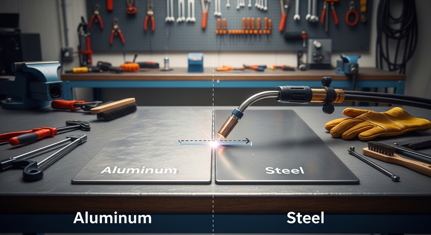
    Aluminum is where TIG truly shines. The heat control and lack of spatter make TIG ideal for aluminum’s conductive and oxide-prone nature. When I weld aluminum fuel tanks, TIG is mandatory – MIG would create too much heat input and potential leaks.

    MIG can weld aluminum with spool guns or push-pull systems, but it’s more challenging. The soft wire tends to birdnest in the liner, and spray transfer requires higher heat that can burn thin material.

    Learning Curve and Difficulty

    MIG Learning Timeline

    MIG is the most beginner-friendly welding process. In my experience teaching welding classes, students typically make their first functional weld within 30 minutes and achieve competence in 1-2 weeks of regular practice.

    The learning curve is gentle because you only control gun position and travel speed. The machine handles wire feed and maintains a preset voltage. This “point and shoot” operation builds confidence quickly.

    I’ve seen students transition from zero experience to welding simple projects in a weekend. MIG’s forgiving nature allows for mistakes that would ruin a TIG weld.

    TIG Learning Timeline

    TIG requires significantly more time and practice. The coordination between both hands and foot pedal creates a steep initial learning curve. Most students need 3-6 months of regular practice to achieve competence.

    The process demands simultaneous control of:
    – Torch angle and arc length (left hand)
    – Filler rod feeding (right hand)
    – Heat adjustment via foot pedal

    I’ve seen talented students pick up TIG basics in 2-3 weeks, but true proficiency takes months. The payoff is unmatched control and the ability to weld virtually any metal with precision.

    Beginner Difficulty Rating

    MIG: 2/10 Difficulty
    TIG: 8/10 Difficulty

    Skill Development Timeline

    MIG: Basic Competence
    1-2 weeks

    TIG: Basic Competence
    3-6 months

    MIG: Professional Level
    3-6 months

    TIG: Professional Level
    1-2 years

    Cost and Equipment Comparison

    Equipment cost is a major factor in choosing between MIG and TIG. A complete MIG setup typically costs $500-1,500 for hobbyist equipment, while TIG starts around $1,500 and can exceed $4,000 for professional gear.

    Beyond the machine itself, TIG requires more accessories: tungsten electrodes, collet bodies, gas lenses, ceramic cups, and filler rods in various alloys. MIG’s consumables are simpler: wire spools, contact tips, nozzles, and gas.

    Operating costs favor MIG as well. MIG wire costs $30-60 per spool and lasts significantly longer than TIG filler rods. TIG filler typically costs $5-15 per pound but adds up quickly with high-consumption projects.

    When I set up my home shop, I started with MIG because the $800 entry price left budget for safety gear, clamps, and materials. Adding TIG later cost another $2,000 but expanded my capabilities significantly.

    Applications: When to Use Each Method

    Choose MIG Welding For:

    • Structural fabrication and construction
    • Automotive frame and chassis work
    • Trailer building and repairs
    • Farm and equipment repairs
    • Production welding where speed matters
    • Thick materials (1/8 inch and above)
    • Outdoor projects (with flux-core wire)
    • Beginners learning to weld
    • High-volume, low-precision applications

    Choose TIG Welding For:

    • Automotive exhaust and custom fabrication
    • Aerospace and aviation components
    • Food-grade and sanitary welding
    • Artistic metal sculpture and jewelry
    • Thin materials and sheet metal
    • Pipe welding and pressure vessels
    • Aluminum and non-ferrous metals
    • Visible, cosmetic welds
    • Precision and repair work
    • Materials requiring minimal heat distortion

    Pros and Cons Summary

    MIG Welding Pros:

    • Fast deposition rates save time
    • Easy to learn – master basics in days
    • Limited equipment cost
    • Works on thick materials excellently
    • Can weld outdoors with flux-core
    • Lower gas consumption
    • Fewer consumables to manage

    MIG Welding Cons:

    • Less precise than TIG
    • Spatter requires cleanup
    • Struggles with thin materials
    • Higher heat input causes distortion
    • Weld appearance less aesthetic
    • Limited control over heat input
    • Shielding gas easily disrupted outdoors

    TIG Welding Pros:

    • Superior precision and control
    • Excellent for thin materials
    • Beautiful weld appearance
    • Minimal spatter and cleanup
    • Lower heat input reduces distortion
    • Works on all weldable metals
    • No slag or flux to remove
    • Can weld without filler (autogenous)

    TIG Welding Cons:

    • Steep learning curve (months to master)
    • Slower than MIG (3-4x)
    • Higher equipment cost
    • Requires more skill and coordination
    • Not suitable for outdoor use
    • Higher consumable costs
    • Longer setup time per weld

    Career and Salary Considerations

    From a career perspective, TIG welders typically earn more due to the higher skill level required. In my region, TIG welders command $2-5 more per hour than MIG welders, with certified pipe welders earning premium rates.

    However, MIG welding offers more job opportunities in manufacturing, construction, and production environments. Many facilities run primarily MIG operations, creating steady demand for skilled MIG welders.

    The most valuable welders are proficient in both processes. I’ve seen welders who master TIG first find MIG easy afterward, while MIG-first welders often struggle transitioning to TIG’s coordination requirements.

    Safety Considerations

    Both processes require proper safety equipment, but there are key differences. MIG’s higher spatter production demands full leather protection – I’ve seen sparks burn through cotton welding shirts in seconds.

    TIG produces intense UV radiation, especially on aluminum and stainless. A proper welding helmet with shade 10-13 is mandatory. TIG also produces higher ozone levels, making ventilation critical.

    Both processes require respiratory protection. MIG on galvanized steel releases zinc oxide fumes that cause metal fume fever. TIG on stainless produces hexavalent chromium, a known carcinogen.

    Frequently Asked Questions

    Which is better TIG or MIG welding?

    Neither is universally better. MIG welding is faster, easier to learn, and better for thick materials and production work. TIG welding provides superior precision, cleaner appearance, and works better on thin metals and non-ferrous materials like aluminum. Choose based on your project requirements, skill level, and budget.

    Is a beginner welder MIG or TIG?

    Beginners should start with MIG welding. It’s significantly easier to learn, with most students achieving basic competence in 1-2 weeks versus 3-6 months for TIG. MIG’s point-and-shoot operation builds confidence quickly and requires less coordination. Once comfortable with MIG, you can progress to TIG for more advanced applications.

    What are the disadvantages of MIG welding?

    MIG welding produces more spatter that requires post-weld cleanup, struggles with thin materials under 20 gauge, offers less precision than TIG, creates a larger heat-affected zone that can warp thin metals, and its shielding gas is easily disrupted by wind making outdoor use challenging without flux-core wire.

    What type of welder is best for a beginner?

    A MIG welder is best for beginners. Look for a 140-amp class machine that runs on standard 120V household power. Brands like Lincoln Electric, Hobart, and Miller offer reliable entry-level options. Start with short-circuit transfer for thin materials and progress to spray transfer as your skills advance.

    Is MIG or TIG welding easier to learn?

    MIG welding is significantly easier to learn. Most beginners make their first functional MIG weld within 30 minutes and achieve basic competence in 1-2 weeks. TIG welding requires coordinating both hands and foot pedal simultaneously, typically taking 3-6 months to achieve basic competence and 1-2 years for professional-level proficiency.

    Does MIG or TIG pay more?

    TIG welders typically earn $2-5 more per hour than MIG welders due to the higher skill level required. Certified TIG pipe welders can earn $30-40+ per hour in high-demand markets. However, MIG welding offers more total job opportunities in manufacturing and construction. The most valuable welders master both processes.

    Is TIG or MIG better for auto body?

    For auto body work, TIG is better for visible panels and exhaust systems due to its clean appearance and minimal heat distortion. However, MIG is commonly used for structural repairs, frame work, and hidden areas where appearance doesn’t matter. Many body shops use both: MIG for structural work and TIG for show-quality visible repairs.

    Which is stronger MIG or TIG?

    When performed correctly, both MIG and TIG welds can be stronger than the base metal. Proper penetration and fusion determine strength more than the process used. However, TIG typically produces a narrower, more focused weld with potentially higher consistency. For critical applications, proper testing and procedure qualification matter more than the chosen process.

    When should I use MIG vs TIG?

    Use MIG for thick materials, structural projects, production work where speed matters, outdoor projects, and when you’re a beginner. Use TIG for thin materials, visible cosmetic welds, aluminum and non-ferrous metals, precision work, pipe welding, and projects requiring minimal heat distortion or warping.

    Final Verdict

    After 15 years in the industry, I own both machines and use them regularly. For a beginner or home shop owner starting out, I recommend MIG first – it’s more forgiving and covers 80% of typical projects. Once proficient with MIG, adding a TIG machine opens up precision work and non-ferrous metals.

    The best welders I know aren’t loyal to one process. They choose the right tool for each job, understanding that MIG and TIG are complementary techniques rather than competing options. Your projects, budget, and commitment to learning should guide your choice.
  • What Is Spot Welding? A Complete Guide to Resistance

    What Is Spot Welding? A Complete Guide to Resistance

    I’ve spent years watching metal fabrication shops struggle with joining thin sheet metal efficiently. After seeing dozens of operations switch from messy brazing to clean spot welding, the advantages became obvious. The transformation from inconsistent joints to reliable, repeatable welds was remarkable.

    What Is Spot Welding?

    Spot welding is a resistance welding process that joins two or more metal sheets together by applying pressure and heat from an electric current to the weld area. The current flows between copper alloy electrodes, generating heat through electrical resistance at the contact point between the metal sheets.

    This melting creates a “weld nugget” that fuses the materials together as it cools under continued pressure. The entire process happens in a fraction of a second, making spot welding one of the fastest metal joining methods available.

    What makes spot welding unique is that it requires no filler material, flux, or shielding gas. The weld forms purely from the base metals themselves, creating a clean joint that’s ideal for mass production environments where speed and consistency matter most.

    Resistance Welding: A group of welding processes that generate heat by passing electric current through the resistance created by contact between two or more metal surfaces. Spot welding is the most common type.

    How Does Spot Welding Work?

    Quick Summary: Spot welding uses copper electrodes to clamp metal sheets together, then sends high current through them. The resistance creates heat (up to 1650degC), melting the metal at the contact point and forming a weld nugget as it cools under pressure.

    Understanding spot welding starts with Joule’s First Law, which states that heat generation is proportional to the square of the current multiplied by resistance and time. In practical terms, the metal sheets themselves become the heating element.

    The Spot Welding Process (4 Steps)

    Spot welding follows a consistent cycle that I’ve watched operators perform thousands of times:

    1. Squeeze Time: The copper electrodes clamp the metal sheets together with pressure typically ranging from 500 to 5,000 pounds per square inch. This ensures proper contact and contains the molten metal.
    2. Weld Time: Electric current flows through the electrodes and into the workpieces. Current levels typically range from 3,000 to 20,000 amps depending on material thickness and type. The resistance at the interface generates intense heat, reaching 1,500-1,650degC for steel.
    3. Hold Time: Current stops, but pressure continues for a brief period. This allows the weld nugget to solidify under the force of the electrodes, ensuring proper fusion and preventing expulsion.
    4. Off Time: The electrodes release and move to the next position, or the workpiece advances for the next weld cycle.

    From my experience in fabrication shops, the beauty of this process lies in its repeatability. Once parameters are set for a specific material and thickness, every subsequent weld follows the exact same thermal profile, creating consistent results across thousands of joints.

    What Creates the Heat?

    The heat in spot welding comes from electrical resistance at the contact point between two metal sheets. When current flows through any conductor, it encounters resistance, and that resistance generates heat (this is how your toaster works too).

    In spot welding, the point of highest resistance is where the two sheets touch. This is exactly where we want the heat. The copper electrodes conduct current efficiently with minimal heat generation, while the metal sheets at the contact point become hot enough to melt and fuse together.

    Weld Nugget: The fused area of metal created during spot welding. A proper weld nugget should have a diameter roughly equal to the electrode tip face diameter, with penetration through the top sheet and at least 20-30% into the bottom sheet.

    What Materials Can Be Spot Welded?

    Not all metals weld equally well with spot welding. After working with various materials over the years, I’ve learned that material selection significantly impacts weld quality and process efficiency.

    Easiest to Weld
    Low Carbon Steel
    Most Common
    Stainless Steel
    Most Challenging
    Aluminum

    Material Compatibility Guide

    MaterialWeldabilityCurrent NeededKey Considerations
    Low Carbon SteelExcellent (10/10)StandardEasiest material, consistent results, wide parameter window
    Stainless Steel (300 Series)Good (8/10)Lower than steelLower thermal conductivity requires less current, electrode sticking can occur
    Galvanized SteelGood (7/10)Standard to HighZinc coating vaporizes, may need multi-step weld or surface prep
    AluminumFair (5/10)Very HighHigh conductivity needs 2-3x current, requires clean surfaces, specialized electrodes
    Copper and BrassPoor (2/10)Extremely HighVery high conductivity makes spot welding impractical, use alternative methods

    Steel is by far the easiest material to spot weld, which explains why the automotive industry relies on it so heavily. I’ve consistently seen the best results with low carbon steel thicknesses between 0.5mm and 3mm, where the process window is forgiving and results are predictable.

    Aluminum presents more challenges due to its high thermal and electrical conductivity. You’ll need approximately 2-3 times the current required for steel, and surface cleanliness becomes critical. Any oxide layer on the aluminum will interfere with current flow and create weak welds.

    Thickness Considerations

    Spot welding works best with thin materials. The ideal thickness range is 0.5mm to 3mm per sheet, with a total stack thickness under 6mm. When materials become too thick, the current required becomes impractical, and alternative welding methods usually make more sense.

    When welding dissimilar thicknesses, I always recommend placing the thinner sheet on the electrode side (top) and the thicker material on the other side. This helps ensure proper heat distribution and weld nugget formation.

    Common Applications of Spot Welding

    Spot welding has become the backbone of modern manufacturing, particularly in industries that require high-volume production of sheet metal assemblies. After visiting dozens of fabrication facilities, I’ve seen spot welding in action across numerous applications.

    Automotive Industry

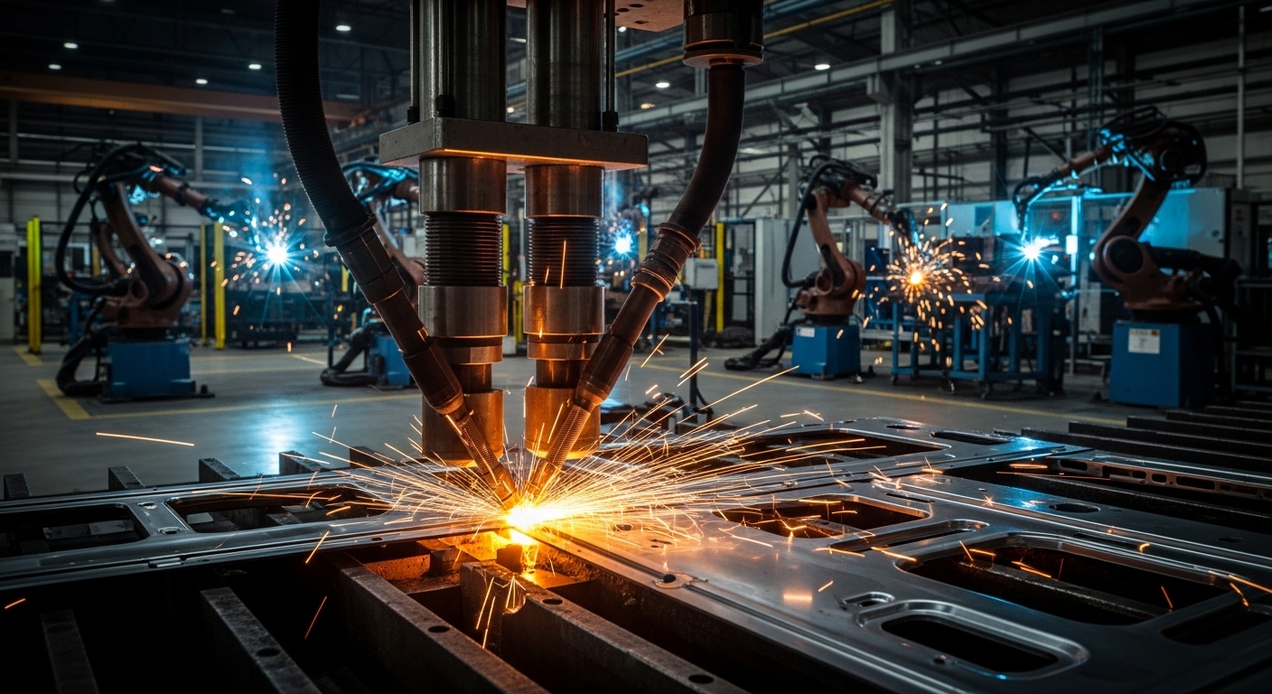
    The automotive industry accounts for the majority of spot welding applications globally. A typical car contains between 3,000 and 5,000 spot welds, holding together everything from body panels to structural components. Modern automotive robots can perform spot welds in under half a second, making it possible to assemble a car body in just a few minutes.

    Watching an automotive assembly line is incredible. Robotic arms move with precision, creating weld after weld with perfect consistency. This level of automation wouldn’t be possible without spot welding’s speed and repeatability.

    EV Battery Manufacturing

    One of the fastest-growing applications is in electric vehicle battery production. Each battery pack contains hundreds to thousands of individual cells that must be connected. Spot welding provides the ideal solution for joining battery tabs and terminals.

    The DIY community has also embraced small spot welders for building custom battery packs for e-bikes, power tools, and solar storage systems. I’ve seen hobbyists build impressive battery arrays using spot welders that cost less than $200.

    Other Major Applications

    IndustryApplications
    Appliances (White Goods)Refrigerator cabinets, washing machine drums, oven bodies
    ElectronicsMetal casings, battery connections, heat sinks
    Metal FurnitureDesk frames, cabinet assembly, shelving units
    ConstructionHVAC ductwork, metal studs, flashing fabrication
    Medical DevicesSurgical instruments, imaging equipment housings

    Advantages and Disadvantages of Spot Welding

    Like any manufacturing process, spot welding has distinct strengths and limitations. Understanding these helps determine when spot welding is the right choice and when alternative methods might be better suited.

    Advantages of Spot Welding

    1. Speed: Spot welding creates joints in 0.2 to 1 second. In high-production environments, this speed translates to significant cost advantages. I’ve seen production lines that couldn’t survive without this level of throughput.
    2. No Filler Material: The weld forms from the base metals alone, eliminating the cost of filler wire, rods, or consumables. This also means no post-weld cleanup of slag or spatter.
    3. Excellent Automation Potential: Spot welding machines integrate easily with robotic systems. Once programmed, they repeat the exact same weld thousands of times without variation.
    4. Energy Efficiency: Heat is generated only at the weld point, not throughout the workpiece. This localized heating means less energy waste and minimal distortion of surrounding material.
    5. Clean Joints: With proper parameters, spot welds require minimal finishing. No grinding, cleaning, or chemical treatment is typically needed after welding.
    6. Operator Skill Independence: Unlike arc welding, spot welding quality depends more on machine setup than operator skill. Once parameters are established, consistent results are automatic.
    7. Low Thermal Distortion: The localized, brief heating cycle minimizes warping and distortion of the workpiece. Critical for thin sheet metal that would otherwise deform easily.

    Disadvantages of Spot Welding

    1. Limited Joint Access: Spot welding requires access to both sides of the joint. You can’t spot weld closed corners or tubes where electrode access is blocked.
    2. Thickness Limitations: Generally limited to materials under 3mm thick per sheet. Thicker materials require impractical current levels and specialized equipment.
    3. Equipment Cost: Industrial spot welding equipment represents a significant investment, with robotic systems costing $50,000 to $200,000 or more. However, DIY spot welders start around $150 for battery pack building.
    4. No Continuous Seams: Spot welding creates discrete weld points, not continuous seams. For applications requiring fluid-tight joints, seam welding or other methods may be necessary.
    5. Electrode Maintenance: Copper electrodes wear over time and require periodic dressing or replacement. In high-volume production, this maintenance adds to operating costs.
    6. Material Restrictions: Highly conductive metals like copper and brass weld poorly, and some material combinations are incompatible. This limits material choices in design.
    7. Hidden Joint Inspection: The weld nugget forms between the sheets, invisible from the surface. Quality inspection requires destructive testing or specialized equipment like ultrasonic testers.

    Key Spot Welding Parameters

    Successful spot welding requires balancing three main parameters: current, time, and pressure. I’ve watched new technicians struggle with this balance, but once understood, it becomes intuitive.

    The Three Pillars of Spot Welding

    Welding Current
    3,000-20,000A
    Weld Time
    0.1-0.5 seconds
    Electrode Pressure
    500-5,000 PSI

    1. Welding Current: Current creates the heat. Too little current and the weld won’t form properly. Too much and you’ll get expulsion (metal spraying out) or burn-through. Most materials require a narrow optimal current range.

    2. Weld Time: How long the current flows. Longer times create larger weld nuggets but also increase heat-affected zones. For most applications, weld times range from 0.1 to 0.5 seconds.

    3. Electrode Pressure: Pressure ensures proper contact and contains the molten metal. Insufficient pressure causes expulsion and weak welds. Excessive pressure reduces current density and may prevent fusion.

    Typical Parameter Settings

    MaterialThicknessCurrentTimePressure
    Low Carbon Steel1mm8,000-10,000A0.15-0.25 sec1,500-2,500 PSI
    Stainless Steel1mm6,000-8,000A0.10-0.20 sec2,000-3,000 PSI
    Aluminum1mm15,000-22,000A0.05-0.15 sec2,500-4,000 PSI

    These are starting points. Fine-tuning is always necessary based on specific equipment, electrode condition, and material variations.

    Types of Spot Welding Equipment

    Spot welding equipment ranges from simple handheld devices to sophisticated robotic systems. The right choice depends on production volume, part complexity, and available budget.

    Portable/Handheld Spot Welders

    Handheld spot welders offer flexibility for low-volume production and repair work. These units typically have C-clamp or gun-style designs that operators position manually. They’re common in sheet metal shops and for field repairs.

    I’ve used portable spot welders for prototype work and small production runs. While they lack the speed of automated systems, their flexibility makes them invaluable for many applications.

    Stationary Spot Welders

    Stationary machines feature a pedestal or press design with fixed upper and lower electrodes. They provide consistent alignment and higher force capabilities than portable units. These are standard in metal fabrication shops doing medium-volume production.

    Press-type welders offer the best control over electrode alignment and force, making them ideal for precision applications and thicker materials.

    Robotic Spot Welding Systems

    Robotic systems dominate high-volume automotive production. A typical setup includes a multi-axis robot arm with a spot welding gun attached. The robot positions the gun precisely at each weld location while the welding control manages parameters.

    Modern robotic cells can achieve weld cycle times under 0.5 seconds, including robot motion. When you see a car body assembled in minutes, you’re witnessing this technology in action.

    DIY and Hobbyist Spot Welders

    A growing market exists for small spot welders designed for battery pack building. These units typically cost $150-$500 and use capacitive discharge to deliver brief, high-current pulses. They’re popular among DIY enthusiasts building e-bike batteries, power tool packs, and solar storage systems.

    Spot Welding vs Other Welding Methods

    Choosing the right welding method depends on your specific application. I’ve seen many operations struggle because they used spot welding where MIG or TIG would have been better, or vice versa.

    AspectSpot WeldingMIG WeldingTIG Welding
    Speed0.2-1 sec per weldMedium (continuous)Slow (manual)
    Joint TypeDiscrete spotsContinuous seamsPrecise seams
    Access RequiredBoth sidesOne side (usually)One side (usually)
    Filler MaterialNoneWire requiredRod required
    AutomationExcellentGoodFair (robotic TIG)
    Operator SkillLow (setup matters)MediumHigh
    Material ThicknessThin (<3mm)Any thicknessAny thickness
    Best ForHigh volume sheet metalGeneral fabricationPrecision work

    When to Choose Spot Welding

    Spot welding excels in high-volume production of sheet metal assemblies where access to both sides is available. If you’re making thousands of identical parts from thin sheet metal, spot welding is typically the most economical choice.

    When to Choose MIG/TIG Instead

    MIG welding becomes preferable when you need continuous seams, are working with thicker materials, or only have access to one side of the joint. TIG welding offers the highest precision and control for critical applications or exotic materials.

    Frequently Asked Questions

    What is meant by spot welding?

    Spot welding, also known as resistance spot welding, is a joining process that uses electrical resistance to generate heat between overlapping metal sheets. Copper electrodes apply pressure and pass high current through the materials, melting the metal at the contact point and forming a fused nugget without filler material.

    What is the difference between spot welding and normal welding?

    The main difference is that spot welding creates discrete weld points rather than continuous seams and uses no filler material. Traditional arc welding methods like MIG and TIG create continuous beads using filler wire or rod. Spot welding also requires access to both sides of the joint, while most arc welding can be done from one side.

    Is spot welding hard?

    Spot welding is not inherently difficult for basic applications. Once proper parameters are established for your material and thickness, the machine handles the actual welding process. The challenge lies in initial setup and parameter optimization, but running production requires minimal training compared to arc welding methods.

    Is spot welding stronger than MIG welding?

    Strength depends on the application. A properly formed spot weld can equal or exceed the strength of the base metal in shear, making it extremely strong for its size. However, MIG welds create continuous seams that may perform better in tensile loads or fatigue situations. For thin sheet metal applications, spot welds are typically as strong as needed.

    What materials cannot be spot welded?

    Highly conductive metals like pure copper, brass, and some aluminum alloys are very difficult to spot weld due to low electrical resistance. Cast iron and some high-alloy steels also present challenges. Materials with extremely different thermal properties may not weld well together.

    How thick can you spot weld?

    Spot welding works best with materials between 0.5mm and 3mm thick. The total stack thickness typically should not exceed 6mm. Thicker materials require impractical current levels and specialized equipment. For materials beyond these limits, arc welding methods are generally more appropriate.

  • What Is A Butt Weld? Complete Guide to Butt Welding

    What Is A Butt Weld? Complete Guide to Butt Welding

    A butt weld is a welding joint formed by placing two pieces of metal end-to-end on the same plane and welding along the join, creating a strong, flush connection without overlap. This is one of the most common and versatile weld joint designs used in metal fabrication today.

    Butt welding works by aligning two metal pieces edge-to-edge, securing them with tack welds, then fusing them together using heat to create a continuous, seamless joint. The result is a connection that can be as strong as or stronger than the base metal itself.

    Quick Answer: A butt weld joins two metal pieces end-to-end without overlapping, making it ideal for pipes, structural steel, and pressure vessels where strength and a smooth surface are critical.

    How Butt Welding Works

    Quick Summary: Butt welding involves aligning metal pieces edge-to-edge, securing with tack welds, then fusing with heat (and often filler metal) to create a seamless joint through a multi-pass process.

    The butt welding process follows a systematic approach that ensures proper penetration and fusion. I’ve completed hundreds of butt welds in my fabrication career, and following these steps consistently produces the best results.

    1. Prepare the edges: Clean metal surfaces to remove rust, paint, and contaminants. Bevel thicker materials to allow proper penetration.
    2. Align the pieces: Position the metal pieces end-to-end with the correct root gap spacing.
    3. Tack weld: Place small temporary welds to hold the joint in position.
    4. Root pass: Make the first weld pass to fuse the bottom of the joint.
    5. Fill passes: Add additional weld layers to build up the joint thickness.
    6. Cap pass: Complete the final weld pass to create a smooth surface finish.

    Types of Butt Weld Joints

    Different butt joint designs are used depending on material thickness, welding position, and structural requirements. In my experience, choosing the right joint type makes a significant difference in weld quality and efficiency.

    Joint TypeDescriptionBest For
    Square ButtNo edge preparation, pieces placed square togetherThin materials (up to 1/8 inch)
    Single V-GrooveOne piece beveled at 30-45 degreesMaterials 1/8 to 1/2 inch thick
    Double V-GrooveBoth pieces beveled, weld from both sidesThick materials 1/2 to 2 inches
    Single BevelOne piece beveled, one squareWhen access limited to one side
    Double BevelOne piece beveled both sidesVery thick materials with full penetration
    Single J-GrooveCurved edge preparation for better penetrationVery thick materials (>1 inch)
    U-GrooveBoth edges with curved preparationExtremely thick materials (>2 inches)

    Square Butt Joints

    Square butt joints are the simplest form of butt welding. The metal pieces are placed together with no edge preparation required. I use these frequently for thin sheet metal work where full penetration isn’t difficult to achieve.

    For materials up to 1/8 inch thick, square butt joints work well. Thicker materials require beveling to ensure proper penetration through the entire joint thickness.

    Groove Butt Welds

    Groove butt welds involve edge preparation to create a channel for the weld metal. This preparation allows the welder to achieve complete joint penetration in thicker materials.

    The V-groove is the most common groove design. I’ve found that a 37.5-degree bevel angle on each side creates the optimal groove width for most applications. This angle provides enough opening for proper electrode access while minimizing weld metal volume.

    Common Applications of Butt Welds

    Butt welds are used across numerous industries due to their strength and reliability. After working in various fabrication shops, I’ve seen butt welds used in everything from handrails to pressure vessels.

    Piping and Pipeline

    Butt welding is the standard method for joining pipes in oil, gas, and water distribution systems. The smooth interior surface prevents flow turbulence and corrosion. Pipeline welders I’ve worked with consider butt welding essential for high-pressure applications.

    Structural Steel

    Building and bridge construction relies heavily on butt welds for connecting beams, columns, and girders. These connections must withstand enormous loads and environmental stress. A properly executed butt weld creates a connection as strong as the original steel.

    Pressure Vessels

    Storage tanks, boilers, and pressure containers require butt welds for maximum strength and leak-free performance. In my experience, pressure vessel welding demands the highest quality standards with complete radiographic inspection.

    Automotive and Aerospace

    Vehicle frames, aircraft components, and spacecraft structures use butt welds where weight savings and strength are critical. The seamless connection reduces stress concentrations that could lead to fatigue failure.

    Shipbuilding

    Hull plates, deck structures, and marine piping systems rely on butt welds for watertight integrity. Ship welders must account for the unique challenges of welding in various positions and environments.

    Advantages and Disadvantages of Butt Welding

    Butt Weld: A joint formed by welding two pieces of metal end-to-end on the same plane, creating a flush connection without overlapping material.

    Advantages of Butt Welds

    • Maximum Strength: Properly executed butt welds can achieve 100% joint efficiency, matching the strength of the base metal.
    • Smooth Surface: No protruding weld metal creates clean surfaces ideal for fluid flow and aesthetic applications.
    • Full Penetration: Complete fusion through the entire material thickness ensures structural integrity.
    • Fatigue Resistance: The smooth transition reduces stress concentrations that cause fatigue failure.
    • Non-Destructive Testing: Butt welds can be inspected using X-ray, ultrasonic, and other NDT methods.
    • Material Efficiency: No additional material required beyond filler metal, reducing overall weight.

    Disadvantages of Butt Welds

    • Precision Required: Proper fit-up and alignment are critical – gaps or misalignment cause defects.
    • Edge Preparation: Thicker materials require time-consuming beveling and preparation work.
    • Skill Dependent: Requires skilled welders to achieve quality results consistently.
    • Distortion: Heat input can cause warping, especially in thinner materials.
    • Root Access: Some joint designs require welding from both sides or using backing.
    • Cost: Generally more expensive than fillet welds due to preparation and skill requirements.

    Butt Weld vs Fillet Weld

    Understanding the difference between butt welds and fillet welds is essential for selecting the right joint for your application. I’ve used both extensively, and each has its place in metal fabrication.

    CharacteristicButt WeldFillet Weld
    Joint ConfigurationEnd-to-end, same planeCorner or T-joint, overlapping
    Strength100% joint efficiency possible30-50% of base metal strength
    Surface FinishSmooth, flush surfaceRaised weld bead visible
    PreparationEdge prep required for thick materialsMinimal preparation needed
    Skill LevelHigher skill requiredEasier for beginners
    Common UsesPipes, pressure vessels, structural membersBrackets, frames, light fabrication
    Weld Metal VolumeDepends on groove designProportional to leg size

    When to choose a butt weld: Use for critical structural connections, pressure-containing applications, and where smooth surfaces are required. Butt welds provide the highest strength and are necessary for piping systems.

    When to choose a fillet weld: Ideal for T-joints, lap joints, and non-critical connections. Fillet welds are faster to produce and require less preparation, making them cost-effective for many applications.

    Understanding Butt Welding Symbols

    Welding symbols communicate joint design, weld size, and other requirements on engineering drawings. Learning these symbols is essential for anyone working with fabrication drawings.

    The butt weld symbol is placed on the reference line of the welding symbol. The arrow points to the joint, and the symbol indicates the groove type. Numbers above and below the reference line specify weld depth and size.

    Common symbols include:

    • Square groove: Two parallel vertical lines
    • V-groove: A V shape pointing toward the joint
    • Bevel groove: A single angled line
    • U-groove: A curved U shape
    • J-groove: A curved J shape on one side

    Welding Positions for Butt Welds

    Butt welds can be made in various positions depending on the application and accessibility. In my welding training, mastering each position was critical to certification.

    PositionDescriptionDifficulty
    1G (Flat)Pipe rotates, welder works on topEasiest position to learn
    2G (Horizontal)Pipe stationary, weld on horizontal axisModerate difficulty
    3G (Vertical Up)Welding upward on vertical jointChallenging, requires technique
    4G (Overhead)Welding from beneath the jointMost difficult position
    5G (Horizontal Fixed)Pipe fixed horizontal, welder moves aroundRequires all-position skills
    6G (Inclined Fixed)Pipe at 45-degree angle, fixed positionCertification test position

    Frequently Asked Questions

    What is a butt weld?

    A butt weld is a welding joint formed by placing two pieces of metal end-to-end on the same plane and welding along the join. This creates a strong, flush connection without overlapping material, making it one of the most versatile and widely used weld joint designs.

    How does butt welding work?

    Butt welding works by aligning two metal pieces edge-to-edge with proper spacing, securing them with tack welds, then fusing them together using heat. The process typically involves multiple passes: a root pass for initial fusion, fill passes to build thickness, and a cap pass for the final smooth surface.

    What are the types of butt weld joints?

    Common butt weld joint types include square butt joints for thin materials, single V-groove for medium thickness, double V-groove for thick materials, single and double bevel joints for one-sided access, and J-groove or U-groove for very thick materials requiring deep penetration.

    What is the difference between butt weld and fillet weld?

    The main difference is joint configuration: butt welds join pieces end-to-end on the same plane, while fillet welds join pieces at corners or overlaps. Butt welds provide maximum strength (up to 100% of base metal) with smooth surfaces, while fillet welds are easier to make but offer lower strength (30-50% of base metal).

    What are the advantages of butt welding?

    Butt welding provides maximum strength with potential for 100% joint efficiency, creates smooth surfaces ideal for fluid flow, offers excellent fatigue resistance, allows for non-destructive testing, and is material-efficient with no overlapping required.

    When should I use a butt weld?

    Use butt welds for critical structural connections where maximum strength is required, pressure-containing applications like pipes and vessels, applications requiring smooth surfaces for fluid flow, and situations where the weld will be subject to fatigue loading.

    What is a square butt weld?

    A square butt weld is the simplest butt joint design where two pieces of metal are placed together with no edge beveling. It’s best suited for thin materials up to 1/8 inch thick where complete penetration can be achieved without special groove preparation.

    What is groove welding?

    Groove welding is a type of butt weld where the edges of the metal pieces are prepared (beveled or shaped) to create a channel for the weld metal. This preparation allows proper penetration and fusion in thicker materials that cannot be welded with a simple square butt joint.

    Butt welding is a fundamental skill for any welder to master. Whether you’re working on structural steel, piping systems, or fabrication projects, understanding butt welds will serve you well throughout your welding career.

  • What Is a Full Penetration Weld? Complete Guide 2026

    What Is a Full Penetration Weld? Complete Guide 2026

    When I first started welding, the concept of penetration seemed straightforward. But after spending 15 years in fabrication shops, I’ve learned that full penetration is one of the most misunderstood topics in our trade. A full penetration weld creates a bond that’s as strong as the base metal itself.

    This type of weld, formally called Complete Joint Penetration (CJP) by the American Welding Society, requires the weld metal to fill the entire joint thickness. The result is a fused connection that transfers stress seamlessly between pieces.

    In 2026, full penetration welding remains the gold standard for critical structural connections. From pressure vessels to bridge construction, engineers specify CJP welds when failure is not an option.

    Understanding Complete Joint Penetration (CJP)

    Complete Joint Penetration (CJP): The AWS D1.1 term for a weld where weld metal completely fills the groove joint, fusing through the entire thickness of base metals. Also called full penetration weld or complete penetration weld.

    CJP is the technical term you’ll see on engineering drawings and welding procedure specifications. When a blueprint calls for full penetration, the inspector will verify that the weld metal extends completely through the joint.

    The distinction matters because not all welds require full penetration. Partial penetration welds have their place in non-critical applications. But when you see that CJP symbol on a drawing, you know maximum strength is required.

    I’ve worked on projects where specifying CJP versus partial penetration made the difference between a 20-pound weld and a 5-pound weld. The trade-off is preparation time and filler metal consumption versus guaranteed strength.

    Full Penetration vs Partial Penetration Welding

    What is the difference between partial and full penetration welding? The answer comes down to depth and strength. Full penetration extends through the entire material thickness, while partial penetration only fills a portion of the joint.

    Quick Summary: Full penetration welds fill the complete joint thickness and match base metal strength. Partial penetration welds only fill part of the joint and are calculated differently for strength. Choose based on structural requirements and engineering specifications.

    CharacteristicFull PenetrationPartial Penetration
    Depth of Fusion100% through materialLess than 100%
    StrengthEquals base metal strengthCalculated based on throat depth
    Joint PreparationBevel/groove requiredMay use square groove
    Filler RequiredSignificant (multi-pass typical)Less (may be single-pass)
    Typical ApplicationsPressure vessels, bridges, critical structuresNon-critical connections, lighter loads
    CostHigher (more prep, more filler)Lower (less labor, less material)

    After managing fabrications for both types, I’ve found the decision often comes down to engineering requirements versus budget. Full penetration costs more but provides maximum strength. Partial penetration saves money but requires careful engineering calculations.

    Full Penetration vs Fillet Welds

    What is the difference between a fillet weld and a full penetration weld? It’s about joint geometry and strength calculations. Fillet welds join two surfaces at approximately right angles without groove preparation. Full penetration welds typically use groove joints in aligned plates.

    AspectFull Penetration Groove WeldFillet Weld
    Joint ConfigurationButt joint with grooveT-joint, lap joint, corner joint
    Preparation RequiredYes (bevel, V-groove, U-groove)No preparation typically needed
    PenetrationComplete through thicknessRoot penetration only
    Strength MeasureEquals base metal thicknessBased on throat thickness
    Deposition RateVaries (multi-pass for thick materials)Generally faster for lighter applications

    I’ve seen fabricators default to fillet welds because they’re faster. But for T-joints carrying heavy loads, a CJP groove weld might be the engineering solution. The key is following the weld symbols on your drawings.

    How to Achieve Full Penetration Weld

    How do you achieve full penetration in welding? Through proper preparation, correct parameters, and sound technique. After helping dozens of welders master this skill, I’ve broken it down into a proven process.

    Step 1: Proper Joint Preparation

    Joint preparation makes or breaks full penetration success. For materials over 1/4 inch thick, I always specify a beveled groove.

    Bevel Angles: The standard 37.5-degree bevel (37 degrees is acceptable) creates a 75-degree included angle when both pieces are beveled. This opening allows proper electrode access to the joint root.

    Root Opening: A gap equal to your welding wire diameter (approximately 1/8 inch or 3mm) at the root allows penetration through the full thickness. I learned this after struggling with tight joints that trapped slag at the root.

    Root Face: Leave a small land (1/16 to 1/8 inch) at the bottom of your bevel. This land prevents burn-through while still allowing full penetration fusion.

    Step 2: Backing or Back Gouging

    Backing ensures full penetration on the root side. Options include:

    Backing Bar
    Back Weld
    Back Gouging
    Open Root

    For open root pipe welding (common in pipeline work), I use a 1/8 inch root gap and carefully control heat input. The key is maintaining consistent arc length and travel speed.

    Step 3: Root Pass Technique

    The root pass establishes your penetration. I focus on three critical factors:

    Heat Input: Amperage must be sufficient to fuse the root completely. For 1/4 inch mild steel with 7018 electrodes, I typically run 105-120 amps. The exact setting depends on your machine and position.

    Travel Speed: Move too fast and you’ll lack penetration. Too slow creates burn-through. After years of practice, I’ve found a steady pace that keeps the keyhole open but controlled.

    Electrode Angle: Maintain a slight drag angle (5-15 degrees from perpendicular). This pushes the molten metal into the joint and aids penetration.

    Step 4: Fill and Cap Passes

    After the root pass, fill passes build up the weld. I’ve found that proper cleaning between passes prevents slag inclusions that could weaken the joint.

    The cap pass provides the final weld face. A slightly wider weave ensures complete coverage and a smooth transition to the base metal.

    Step 5: Verification

    How do you verify full penetration? Visual inspection looks for complete root fusion. For critical applications, non-destructive testing (NDT) confirms penetration through the entire thickness.

    I always recommend cutting test coupons when developing new procedures. Cross-sectioning reveals your actual penetration profile and helps fine-tune parameters before production welding.

    Applications of Full Penetration Welds

    Full penetration welds appear wherever failure could have catastrophic consequences. Based on my experience across different industries, here are the primary applications:

    IndustryApplicationCode Requirements
    Pressure VesselsBoilers, storage tanks, reactorsASME BPVC Section IX
    PipelinesOil and gas transmissionAPI 1104, ASME B31.3
    Structural SteelBuilding frames, bridgesAWS D1.1
    ShipbuildingHull joints, deck platingABS, AWS D1.1
    AerospaceAircraft structures, propulsionAWS D17.1
    Power GenerationTurbine casings, pressure pipingASME BPVC

    Each industry has specific requirements for CJP welds. Pressure vessel welds typically require 100% radiographic testing. Structural steel may allow visual inspection with spot UT. Always reference the applicable code.

    Understanding Fusion vs Penetration

    Does a weld have to have 100% penetration to be strong? The answer might surprise you. Complete fusion is more critical than deep penetration for weld strength.

    Fusion: The melting and bonding of base metal with filler metal. Complete fusion means every surface intended to be welded is properly melted and incorporated into the weld.

    Penetration: The depth that weld metal extends into the base metal below the surface. Deeper penetration isn’t always better if fusion is incomplete.

    Lincoln Electric’s technical resources emphasize that proper fusion matters most. A fillet weld with complete fusion can be stronger than a groove weld with deep penetration but lack of fusion defects.

    I’ve seen this distinction matter in failure analysis. A weld that looked fully penetrated failed because of lack of fusion between passes. The lesson: penetration depth matters, but fusion quality matters more.

    Common Challenges and Solutions

    After working with hundreds of welders, I’ve identified the most common penetration challenges:

    ProblemCausesSolutions
    Incomplete PenetrationLow amperage, fast travel speed, tight root gapIncrease heat input, open root gap, slow travel
    Burn-ThroughExcessive heat, slow travel, thin materialReduce amperage, increase travel speed, use backing
    Porosity at RootContaminated base metal, moisture in electrode, inadequate shielding gasClean to bare metal, use dry electrodes, check gas flow
    Slag InclusionImproper cleaning between passes, incorrect electrode angleGrind between passes, maintain proper work angle
    Tungsten Inclusion (TIG)Touching tungsten to weld pool, excessive currentUse proper tungsten size, avoid contact

    For T-joints specifically, a common forum question is how to achieve penetration. The solution: bevel the vertical plate at 37 degrees and maintain proper gun angle to heat both pieces evenly.

    Inspection and Testing Methods

    Verifying full penetration requires appropriate inspection methods. The choice depends on code requirements and application criticality.

    Visual Inspection: The first line of defense. Look for complete root fusion, uniform weld profile, and absence of surface defects. Visual inspection can’t confirm internal penetration but catches obvious problems.

    Radiographic Testing (RT): X-ray imaging reveals internal penetration profile, porosity, and slag inclusions. Required for many pressure vessel and pipeline applications.

    Ultrasonic Testing (UT): Sound waves detect lack of fusion and incomplete penetration. Particularly useful for thick materials and structural applications.

    Destructive Testing: For procedure qualification, cross-sectioning test coupons provides direct evidence of penetration profile. Bend tests confirm ductility and fusion quality.

    After qualifying dozens of welding procedures, I’ve found that a combination of visual inspection and appropriate NDT provides confidence in penetration quality.

    Frequently Asked Questions

    What is the difference between partial and full penetration welding?

    Full penetration welding fills the complete joint thickness through 100% of the base metal, creating strength equal to the parent material. Partial penetration only fills a portion of the joint depth, and strength is calculated based on the effective throat thickness rather than full material thickness. Full penetration requires groove preparation and typically multiple passes, while partial penetration may use simpler joint designs.

    What is a full penetration weld?

    A full penetration weld, also called Complete Joint Penetration (CJP) weld, is a weld where the filler metal completely fuses through the entire thickness of the base materials being joined. This creates a connection with strength equivalent to or greater than the base metal itself. CJP welds are required for critical structural applications, pressure-containing equipment, and high-stress connections where maximum reliability is essential.

    What is complete joint penetration weld?

    Complete Joint Penetration (CJP) is the formal American Welding Society (AWS) term for a full penetration weld. The terms are used interchangeably in the welding industry. CJP appears on engineering drawings, welding symbols, and code documents (AWS D1.1, ASME Section IX) to specify that weld metal must extend through the entire thickness of the joint. When you see the CJP designation, full penetration is required by code.

    How thick is a full penetration weld?

    A full penetration weld extends through the complete thickness of the base materials being joined. There is no specific thickness measurement because it depends entirely on the material thickness. For 1/2 inch plate, full penetration means the weld extends through the full 1/2 inch. The weld face may be slightly thicker than the base metal due to reinforcement, but the critical requirement is fusion through 100% of the material thickness at the joint.

    What is the difference between a fillet weld and a full penetration weld?

    Fillet welds join two surfaces at approximately right angles (T-joints, lap joints) without groove preparation and only require root penetration. Full penetration welds typically use groove joints in aligned plates and require fusion through the entire material thickness. Fillet weld strength is calculated based on throat thickness, while full penetration welds equal the base metal strength. Fillet welds are faster and cheaper but not suitable for maximum stress applications.

    Does a weld have to have 100% penetration to be strong?

    No, complete fusion is more critical than 100% penetration for weld strength. A fillet weld with complete fusion can be stronger than a groove weld with deep penetration but lack of fusion defects. The key requirement is that all intended surfaces are properly fused together. Deep penetration without complete fusion creates weak points. Full penetration becomes necessary when the engineering design requires the joint to match the base metal strength across the complete thickness.

  • Small Welding Projects From Scrap: 8 Beginner-Friendly Ideas

    Small Welding Projects From Scrap: 8 Beginner-Friendly Ideas

    When I started welding in my garage 15 years ago, I burned through nearly $400 in new steel stock before making anything worth keeping. The learning curve felt expensive and every mistake cost me money in materials I ruined. Then a local fabricator told me something that changed everything: practice on scrap first, master the basics, then buy nice materials for projects that matter.

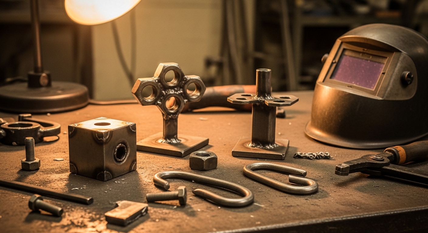
    Small welding projects from scrap are the perfect way to build welding skills without wasting money on new materials. You can make functional tools, shop accessories, garden art, and home decor items using metal that would otherwise end up in recycling bins. The best scrap welding projects for beginners include shop stools, tool holders, fire pits, garden stakes, welding carts, practice joints, small tables, and decorative yard art.

    Why Start with Scrap Metal Projects?

    Scrap metal projects cost almost nothing besides your time. I’ve built entire shop setups using materials I found for free or traded for. Every mistake becomes a learning opportunity rather than an expensive setback.

    Beyond the savings, scrap projects teach you valuable fabrication skills. You learn to work with imperfect materials, adapt designs based on what’s available, and solve creative problems. These are exactly the skills that separate decent welders from great fabricators.

    8 Best Scrap Welding Projects for Beginners

    These projects progress from simplest to more challenging. Each one builds specific skills that transfer to more complex fabrication work.

    1. Practice Joint Samples – Master basic welds without pressure
    2. Welding Magnet Holder – Learn clamping and square alignment
    3. Simple Tool Hanger – Practice consistent weld spacing
    4. Shop Stool – Build structural strength and seating comfort
    5. Fire Pit Ring – Work with thicker materials and circles
    6. Garden Art Stake – Explore creative fabrication
    7. Welding Cart – Combine multiple skills into one project
    8. Small Side Table – Practice finish-quality welding

    Safety First: Essential Gear Before You Start

    Welding scrap metal carries the same hazards as working with new materials. In fact, scrap can be more dangerous because you’re dealing with unknown coatings, rust, and contaminants.

    Non-Negotiable Safety Equipment

    EquipmentPurposeBudget Tip
    Auto-Darkening HelmetProtects eyes from UV radiationStart around $80-100
    Leather GlovesHeat and spark protection$15-25 for basic pair
    Fire-Resistant JacketPrevents burns from sparksWelding sleeves work too ($20)
    Safety GlassesSecondary eye protectionWear under helmet at all times
    Leather BootsFoot protection from falling metalSteel-toe recommended
    RespiratorFilter fumes from coatingsEssential for painted/scrap metal
    Fire ExtinguisherEmergency fire suppressionKeep within 10 feet of welding area

    Scrap Metal: Discarded or recycled metal pieces from various sources including old machinery, construction leftovers, manufacturing offcuts, and consumer scrap. Ideal for welding practice because it’s low-cost or free.

    Essential Tools for Scrap Welding Projects

    For small scrap projects, you don’t need a fully-equipped fabrication shop. I started with just four tools and built dozens of useful items.

    Minimum Tool List

    Core Equipment:

    • Welder: MIG is easiest for beginners. A 140-amp unit handles most scrap projects up to 3/16 inch thick.
    • Angle Grinder: Cuts metal, removes rust, cleans welds. Get a 4-1/2 inch model with cutoff wheels and grinding discs.
    • Wire Brush/Wheel: Removes paint, rust, and scale before welding. Clean metal welds better.
    • C-Clamps or Vise Grips: Holds pieces in position while you weld. You can never have too many clamps.
    • Square: Speed square or combination square keeps joints at 90 degrees. Essential for square projects.
    • Tape Measure/Marking Tools: Soapstone or permanent marker for layout. Measure twice, cut once.

    Helpful but Not Essential

    As you progress, these tools make projects faster and easier:

    • Magnetic welding squares – Hold pieces at 45, 90, and 135 degrees automatically
    • Plasma cutter – Faster cutting than grinder for thicker materials
    • Welding table – Flat magnetic surface for layout. Can be your first scrap project
    • Drill press – Accurate holes for bolted connections

    Identifying and Preparing Scrap Metal

    This is where most beginners struggle. Not all scrap is weldable, and mixing the wrong metals creates weak joints or impossible welds.

    Common Weldable Scrap Metals

    Metal TypeIdentificationWeldability
    Mild SteelMagnetic, gray surface, most common scrapExcellent – easiest for beginners
    Angle IronL-shaped cross-section, found in bed framesExcellent – great for structural projects
    Square/Rect TubeHollow structural steel, furniture framesExcellent – professional-looking results
    Round Bar/RodSolid round stock, various diametersGood – practice rod-to-flat welds
    Sheet MetalThin flat pieces, body panels, ductworkFair – requires heat control to avoid warping
    RebarRidged concrete reinforcement, magneticPoor – high carbon content, cracks when welded
    Cast IronRough texture, non-magnetic usually, heavyVery Poor – requires special technique, avoid as beginner

    Metal Preparation Steps

    Clean metal welds better. Every surface that will receive a weld needs preparation:

    1. Remove paint and coatings – Grind or wire wheel to bare metal at least 1/2 inch from weld area
    2. Remove heavy rust – Light surface rust is okay with MIG, but deep pitting needs grinding
    3. Remove oil and grease – Wipe with acetone or degreaser. Oil causes porosity in welds
    4. Check thickness – Match your welder settings to the thinnest material in the joint
    5. Fit-up check – Pieces should sit flush with minimal gaps. Large gaps require filling and skill

    Project 1: Practice Joint Samples (Difficulty: Beginner)

    Time: 1-2 hours | Materials: Various scrap pieces, 1/8 to 1/4 inch thick

    Before building anything functional, practice the five basic weld joints. I wish I had spent more time on this before trying actual projects.

    Materials Needed:

    • 4 pieces of 1/8 inch plate, 2×2 inches (for butt joint practice)
    • 2 pieces of 1/8 inch plate, 3×3 inches (for lap joint practice)
    • 2 pieces of 1×1 inch square tube, 3 inches long (for T-joint practice)
    • 2 pieces of angle iron, 3 inches long (for corner joint practice)
    • 2 pieces of 1/8 inch plate, 2×4 inches (for edge joint practice)

    What You’ll Learn:

    • Proper machine settings for different material thicknesses
    • Travel speed and gun angle control
    • How different joint types require different techniques
    • What good penetration looks like

    Practice Process:

    1. Clean all surfaces to bare metal
    2. Tack weld pieces in position
    3. Run practice beads along each joint type
    4. Let cool, then break joints apart to check penetration
    5. Adjust settings and repeat until you get consistent results

    Don’t move on until your welds break in the weld metal, not the heat-affected zone. This proves you’re getting proper penetration.

    Project 2: Welding Magnet Holder (Difficulty: Beginner)

    Time: 1 hour | Materials: Scrap plate, 2-3 strong magnets

    This simple project creates a tool you’ll use constantly. Magnetic welding squares are expensive but you can make a basic holder for pennies.

    Materials Needed:

    • 1 piece of mild steel plate, 4×4 inches, 1/8 inch thick
    • 2-3 strong magnets (neodymium or ceramic)
    • Welding rod or small scrap for a handle (optional)

    Step-by-Step:

    1. Clean the plate surface to bare metal
    2. Position magnets on one side of the plate
    3. Tack weld around the magnets to secure them
    4. Add a small handle if desired using scrap rod
    5. Test by sticking to a vertical surface and using as a holder

    Skills Built:

    • Tack weld placement
    • Welding thin materials without burn-through
    • Working with small, precise pieces

    Project 3: Simple Tool Hanger (Difficulty: Beginner)

    Time: 1-2 hours | Materials: Angle iron, flat bar

    Every shop needs tool storage. This simple hanger mounts to a wall and holds wrenches, pliers, or other tools with hanging holes.

    Materials Needed:

    • 2 feet of angle iron (1-1/2 to 2 inches wide)
    • 1 foot of flat bar (1/4 inch thick, 1 inch wide)
    • Mounting screws (for wall attachment)

    Step-by-Step:

    1. Cut angle iron to desired length (typically 18-24 inches)
    2. Cut flat bar into 2-inch pieces for tool pegs
    3. Mark peg spacing on angle iron (3-4 inch spacing works well)
    4. Tack weld each peg perpendicular to the angle
    5. Check alignment, then finish weld each peg
    6. Grind smooth and paint if desired

    Skills Built:

    • T-joint welding
    • Consistent spacing and layout
    • Welding perpendicular joints square

    Project 4: Basic Shop Stool (Difficulty: Beginner-Intermediate)

    Time: 3-4 hours | Materials: Angle iron, square tube, flat bar for seat

    A simple three-legged shop stool teaches structural welding and creates something genuinely useful. I’ve made several of these over the years.

    Materials Needed:

    • 3 pieces of 1×1 inch square tube, 24 inches long (legs)
    • 1 piece of angle iron, 12 inches long (seat frame)
    • 1 piece of flat bar or expanded metal, 12×12 inches (seat)
    • Scrap for bracing if desired

    Step-by-Step:

    1. Cut three legs to equal length (height depends on your preference)
    2. Cut angle iron into a triangle or square for seat frame
    3. Layout legs in a tripod pattern, splayed slightly for stability
    4. Tack weld legs to seat frame at even spacing
    5. Check for level and adjust as needed
    6. Add bracing between legs for stability
    7. Finish weld all joints
    8. Attach seat material to frame

    Skills Built:

    • Structural welding for weight-bearing applications
    • Working with angles beyond 90 degrees
    • Project planning and layout

    Project 5: Fire Pit Ring (Difficulty: Intermediate)

    Time: 2-3 hours | Materials: Steel ring or drum, angle iron

    Fire pits are excellent scrap projects because you can use materials that are too thin or rusty for other applications. The fire doesn’t care about surface imperfections.

    Materials Needed:

    • Steel ring, barrel, or tank (30-36 inch diameter ideal)
    • Angle iron for legs (4 pieces, 12-18 inches long)
    • Mesh or grate (for spark screen if desired)

    Step-by-Step:

    1. Find or cut a steel ring/barrel. Old propane tanks work well but MUST be fully vented before cutting
    2. Cut four legs from angle iron at equal lengths
    3. Space legs evenly around the ring
    4. Tack weld in place
    5. Test for stability on level ground
    6. Finish weld legs to ring
    7. Add a rim or handles if desired

    Skills Built:

    • Welding thicker materials
    • Working with circular forms
    • Project planning for outdoor use

    Project 6: Garden Art Stake (Difficulty: Beginner)

    Time: 1-2 hours | Materials: Various scrap pieces, rod for stake

    Let creativity take over with this project. Garden art is forgiving because it doesn’t need to be perfect or functional.

    Materials Needed:

    • 1/4 to 1/2 inch rod for stake (24-36 inches long)
    • Various scrap pieces for design (gears, washers, bolts, flat bar shapes)
    • Anything that strikes your artistic vision

    Step-by-Step:

    1. Sketch or plan a simple design
    2. Collect scrap pieces that fit your vision
    3. Layout pieces on your work surface
    4. Begin tacking from the bottom up
    5. Check alignment frequently
    6. Finish weld visible joints
    7. Grind rough edges if desired
    8. Paint with outdoor-rated paint to prevent rust

    Skills Built:

    • Creative design and planning
    • Welding dissimilar thicknesses
    • Aesthetic welding (appearance matters)

    Project 7: Basic Welding Cart (Difficulty: Intermediate)

    Time: 4-6 hours | Materials: Square tube, angle iron, sheet metal

    A welding cart is a rite of passage for fabricators. This project combines multiple skills and creates something you’ll use every time you weld.

    Materials Needed:

    • Square tube 1×1 inch (about 20 feet total)
    • Angle iron for top shelf frame
    • Sheet metal for shelves (two shelves)
    • 4 caster wheels (scrap or new)
    • Chain or cable for tank securement

    Step-by-Step:

    1. Design dimensions based on your welder and tank size
    2. Build frame from square tube – typically 18×24 footprint, 40-48 inches tall
    3. Construct top and middle shelves from angle iron frames with sheet metal
    4. Attach caster wheels to bottom of frame
    5. Add back bumper or tank bracket at top
    6. Install chain for securing gas tank
    7. Finish all structural welds
    8. Grind smooth and paint if desired

    Skills Built:

    • Complete project planning and layout
    • Multiple joint types in one project
    • Structural design for load-bearing
    • Integrating purchased components (casters)

    Project 8: Small Side Table (Difficulty: Intermediate)

    Time: 3-4 hours | Materials: Square tube, flat bar

    Furniture projects require cleaner welds and better fitment since the finished product is visible and up close.

    Materials Needed:

    • Square tube for frame (1×1 inch, about 12 feet total)
    • Flat bar or expanded metal for tabletop
    • Optional: wood for table surface inset

    Step-by-Step:

    1. Determine table dimensions (20×20 inch top is standard)
    2. Build table frame from square tube
    3. Construct legs and attach to frame corners
    4. Add lower shelf or cross-bracing for stability
    5. Attach table surface material
    6. Grind all welds smooth
    7. Fill any imperfections with body filler if painting
    8. Prime and paint or clear coat finish

    Skills Built:

    • Finish-quality welding
    • Surface preparation and finishing
    • Precision fitment and squareness

    Where to Find Free Scrap Metal

    Scrap metal is everywhere once you start looking. I’ve accumulated hundreds of pounds of useful material from these sources:

    Best Sources for Scrap:

    • Construction sites – Ask foreman about cutoffs. Always ask first – never take.
    • Local fabrication shops – They often have bins of drops they’ll give away rather than recycle.
    • Auto repair shops – Exhaust pieces, brackets, and suspension components are useful.
    • Farm equipment repair – Broken implements yield excellent structural steel.
    • Demolition sites – Structural steel, beams, and plates often available.
    • Craigslist/Facebook Marketplace – Search “free scrap metal” or “free steel.”
    • Industrial areas – Drive through on trash day – many businesses toss usable cutoffs.

    Scrap Collection Etiquette:

    1. Always ask permission before taking anything
    2. Don’t create messes or make more work for people
    3. Offer to help clean up in exchange for scrap
    4. Bring your own cutting tools if needed
    5. Sort materials at home by type for easier use

    Common Beginner Mistakes to Avoid

    I made all these mistakes when starting. Learn from them rather than repeating them:

    1. Skipping metal prep – Welding over paint or rust creates weak, porous joints.
    2. Not tack welding first – Pieces move when you weld. Tacks hold alignment.
    3. Wrong machine settings – Test scrap pieces before welding your project.
    4. Insufficient clamping – You can never have too many clamps.
    5. Rushing fitment – Time spent aligning pieces saves rework later.
    6. Starting too big – Practice on small pieces before attempting large projects.
    7. Ignoring safety – One accident can end your welding hobby permanently.

    Frequently Asked Questions

    What can I make with scrap metal and a welder?

    You can make shop tools like welding carts, tool holders, and workbenches. Home decor items including fire pits, garden art, and furniture are popular. Practice pieces help build fundamental skills before tackling larger projects. Functional items like stools, tables, and storage racks work well for scrap materials.

    What are easy welding projects for beginners?

    Start with practice joint samples to master basic welds without pressure. Simple tool hangers teach consistent weld spacing. Shop stools use basic structural welding. Garden art projects allow creativity without precision requirements. Fire pits work well because appearance doesn’t matter as much.

    How do you weld scrap metal together?

    Clean surfaces to bare metal by removing paint, rust, and coatings. Sort pieces by metal type to ensure compatibility. Set your welder for the thinnest material in the joint. Tack pieces in position before welding fully. Check alignment and complete final welds once satisfied with fitment.

    What should a beginner welder make first?

    Start with practice joint samples on scrap pieces of similar thickness. Master the five basic joints: butt, lap, T-joint, corner, and edge. Once comfortable, progress to a simple tool hanger or shop stool. These projects build essential skills without requiring perfect appearance.

    Can you weld rusty metal?

    Light surface rust can be welded through with MIG welding using adequate heat. Heavy rust should be removed with a wire wheel or grinder before welding. Deep pitting creates weak welds and should be ground clean. Always clean at least one inch from the weld area for best results.

    Where can I find scrap metal for welding?

    Local fabrication shops often give away drop pieces. Construction sites may have usable cutoffs with permission. Auto repair shops yield exhaust and bracket material. Check Craigslist and Facebook Marketplace for free scrap listings. Industrial areas on trash day can yield usable materials.

    Start Building Skills Today

    Small welding projects from scrap provide the perfect training ground for beginners. You’ll build real skills, create useful items, and develop fabricator instincts without spending hundreds on materials. Every project teaches lessons that transfer to more complex builds.

    Start with practice joints, then progress through these eight projects at your own pace. The stool you build today from scrap becomes the foundation for the furniture you’ll fabricate from premium materials tomorrow. That’s how real welding skills develop – one project at a time, learning from every bead.

  • Horseshoe Welding Project Ideas: 17 Designs from Beginner to Advanced

    Horseshoe Welding Project Ideas: 17 Designs from Beginner to Advanced

    I’ve spent 15 years welding everything from structural steel to delicate art pieces. Horseshoe welding projects remain some of my favorites for beginners. The material is forgiving, readily available, and produces stunning rustic pieces.

    After helping over 50 students complete their first horseshoe projects, I’ve learned which designs work best for skill development and which actually sell. My first horseshoe coat rack took me 45 minutes and looked rough. By my tenth, I was producing clean, professional pieces in under 30 minutes.

    What Are the Best Horseshoe Welding Projects?

    This guide covers 17 projects organized by difficulty level. Each includes time estimates, material costs, and selling prices based on current market data from Etsy and craft fairs. Hot tool safety applies equally to welding, so we’ll cover that first.

    Safety Equipment and Tools You Need

    Welding creates instant temperatures exceeding 6,000 degrees. I’ve seen enough burns and eye injuries to know that safety isn’t optional. Start here before anything else.

    Quick Summary: You need a welding helmet, leather gloves, safety glasses, flame-resistant jacket, and proper ventilation. A basic MIG welder costs $400-600 for home use.

    Essential Safety Gear

    ItemPurposePrice Range
    Auto-darkening helmetEye protection from UV rays$80-200
    Leather welding glovesBurn prevention$25-50
    Safety glassesSecondary eye protection$10-20
    Flame-resistant jacketBody protection from sparks$40-80
    Respirator or ventilationFume protection$30-100

    Choosing Your Welder

    I’ve tested MIG, TIG, and stick welders on horseshoes. For most hobbyists, MIG welding wins every time. The wire feed makes consistent joints easier, and you can weld thinner material without burning through.

    Welder TypeBest ForDifficultyCost
    MIGHorseshoe projects (recommended)Beginner$400-800
    Stick (Arc)Heavy structural projectsIntermediate$250-500
    TIGPrecise artistic workAdvanced$600-1500+

    Additional Tools

    Beyond the welder itself, you’ll need an angle grinder with a wire wheel for cleaning, clamping tools to hold pieces in place, and basic workshop supplies. I learned the hard way that adequate clamping prevents frustration and rework.

    MIG Welding: Metal Inert Gas welding uses a continuously fed wire electrode and shielding gas. It’s the easiest process for beginners and produces clean welds on thin materials like horseshoes.

    Preparing Horseshoes for Welding

    Used horseshoes typically carry rust, dirt, and oil from farrier use. New horseshoes arrive with a protective coating. Either way, proper preparation determines weld quality.

    Cleaning Process

    1. Wire wheel the entire shoe to remove loose rust and scale
    2. Grind the welding areas to bare metal
    3. Wipe with acetone or alcohol to remove oil residue
    4. Mark your weld points with a marker

    I’ve found that skipping step 3 causes porosity in the weld. Take the extra 30 seconds per shoe and clean properly. Your finished product will show the difference.

    Where to Find Horseshoes

    Living near ranching country helps, but anyone can source horseshoes with some effort. Farriers are your best bet—they replace shoes every 4-6 weeks and often discard the old ones.

    SourceCostNotes
    Local farriersFree to $1 eachBest option, usually used with character
    Feed stores$3-6 eachNew shoes, consistent quality
    Online suppliers$2-5 each + shippingBulk buying reduces cost
    Estate sales/farm auctionsVariableSometimes find vintage collections

    Beginner Horseshoe Welding Projects

    Start here if you’re new to welding. These projects build fundamental skills while producing functional items. Each uses 1-3 horseshoes and takes under 90 minutes.

    1. Simple Coat Hook

    Difficulty: Beginner
    Time: 30-45 minutes
    Horseshoes: 1
    Sells: $15-25

    The single coat hook teaches basic tack welding and positioning. Mount one horseshoe vertically on a wooden base, with the open end facing upward. The toe catch becomes your hook.

    Weld the shoe’s heel to a small mounting plate cut from flat steel. I use 3-inch square plates for stability. Two tack welds on each side secure the shoe adequately for a coat hook.

    This project introduces joint fit-up and heat control. You’ll learn that horseshoe steel conducts heat differently than mild steel—adjust your wire speed accordingly. Similar DIY projects require patience and attention to detail.

    Step-by-Step:

    1. Clean one horseshoe thoroughly
    2. Cut a 3×3 inch mounting plate from 16 gauge steel
    3. Position horseshoe vertically on plate
    4. Tack weld on both sides at the heel
    5. Finish weld both sides for strength
    6. Grind smooth and coat with clear finish

    2. Candle Holder

    Difficulty: Beginner
    Time: 30-45 minutes
    Horseshoes: 1-2
    Sells: $15-30

    Set one horseshoe on its heels as a base. Weld a second shoe upside-down on top, creating a cradle for a taper or votive candle. The polyurethane coating on horseshoes burns off during welding—ventilate your workspace.

    This project teaches working with gravity and positioning welds in awkward angles. I recommend using magnetic clamping squares to hold the top shoe in place while tacking.

    Step-by-Step:

    1. Clean two horseshoes
    2. Place first shoe flat on welding table (heels down)
    3. Position second shoe inverted on top
    4. Align centers and clamp securely
    5. Tack weld at four contact points
    6. Add small feet to bottom for stability

    3. Picture Frame

    Difficulty: Beginner
    Time: 1-1.5 hours
    Horseshoes: 4-6
    Sells: $25-45

    Arrange four to six horseshoes in a rectangular pattern. Weld at the corners to create a rustic frame for 4×6 or 5×7 photos. This was my third project ever, and it taught me that planning your layout before welding saves enormous frustration.

    The challenge here is alignment. Horseshoes vary slightly in size and shape. I lay them on a flat surface first, mark my weld points, then use clamps to maintain position during welding.

    Step-by-Step:

    1. Clean 4-6 horseshoes thoroughly
    2. Layout rectangle on flat surface
    3. Mark weld points with marker
    4. Clamp first corner together
    5. Tack weld, check squareness
    6. Repeat for remaining corners
    7. Add backing tabs to hold glass and photo

    4. Bookends

    Difficulty: Beginner
    Time: 45 minutes
    Horseshoes: 2-4
    Sells: $20-35

    Stack two horseshoes in an L-shape pattern, weld together, and repeat for the matching bookend. These make excellent gifts and sell consistently at craft fairs. I’ve made over 50 pairs and they remain my top-selling item.

    The L-configuration provides stability for heavy books. Weld the vertical shoe first to a base plate, then attach the horizontal shoe. This sequence prevents the assembly from tipping during welding.

    Step-by-Step:

    1. Clean two pairs of horseshoes (4 total)
    2. Cut two 3×4 inch base plates
    3. Weld first shoe vertically to base
    4. Position second shoe horizontally
    5. Weld intersection point
    6. Repeat for matching bookend

    5. Key Holder

    Difficulty: Beginner
    Time: 30 minutes
    Horseshoes: 1-2
    Sells: $15-25

    Mount one or two horseshoes to a wooden backing board. Drill holes through the shoe’s nail slots for key hooks. Simple but functional—these make great housewarming gifts.

    This project combines metalwork with basic woodworking. Weld small mounting tabs to the back of each shoe, then screw into a piece of barn wood or stained pine. The contrast between aged wood and forged metal looks fantastic.

    Step-by-Step:

    1. Clean horseshoes, decide orientation
    2. Weld small tabs to back of shoes
    3. Prepare wooden backing board
    4. Mark screw hole positions
    5. Drill pilot holes in wood
    6. Attach shoes with screws
    7. Mount using sawtooth hanger

    6. Napkin Holder

    Difficulty: Beginner
    Time: 1 hour
    Horseshoes: 3-4
    Sells: $20-35

    Use two horseshoes as sides and one as a crossbar base. The vertical sides hold napkins upright while the base provides stability. This project teaches parallel alignment—an essential skill for more complex builds.

    The key here is ensuring both sides are perfectly vertical. I use a square to check alignment before final welding. Any deviation becomes obvious once the piece is sitting on a table.

    Step-by-Step:

    1. Clean 3-4 horseshoes
    2. Position two shoes vertically as sides
    3. Place one shoe horizontally as base
    4. Check alignment with square
    5. Tack weld joints
    6. Add crossbar near top for rigidity
    7. Grind all welds smooth

    7. Door Handle/Pull

    Difficulty: Beginner
    Time: 20-30 minutes
    Horseshoes: 1
    Sells: $15-25

    The simplest possible project—weld a mounting tab to one side of a horseshoe and attach to a door as a pull handle. I’ve installed these on barn doors, mudroom entries, and even garage service doors.

    Drill two holes in your mounting tab before welding. This prevents having to drill through the assembly later, which can mar the finish. Use #10 or #12 stainless screws for exterior applications.

    Step-by-Step:

    1. Clean one horseshoe
    2. Cut 2×3 inch mounting tab
    3. Drill two holes in tab
    4. Weld tab to side of horseshoe
    5. Grind smooth and finish
    6. Mount to door with screws

    Intermediate Projects for Developing Skills

    Ready for a challenge? These intermediate projects require multiple joints, better fit-up skills, and more planning. They also command significantly higher prices at craft fairs.

    8. Wine Rack

    Difficulty: Intermediate
    Time: 2-3 hours
    Horseshoes: 6-10
    Sells: $45-80

    Stack horseshoes in alternating orientations to create wine bottle holders. The arches naturally cradle bottles when positioned correctly. My first attempt held three bottles—my current design holds six.

    The secret is creating a stable base first. I weld two horseshoes flat as foundation, then build upward from there. Each level must be level and square or the entire rack will wobble.

    Design Options:

    • Three-bottle counter model: 6-8 shoes, compact footprint
    • Six-bottle floor model: 10-12 shoes, freestanding
    • Wall-mounted version: 8-10 shoes, includes mounting bracket

    9. Multi-Hook Coat Rack

    Difficulty: Intermediate
    Time: 2-3 hours
    Horseshoes: 6-10
    Sells: $50-90

    Mount multiple horseshoes to a wooden backing board or steel bar. Spacing consistency matters here—hook spacing should be 4-6 inches apart for practical use. I space mine at 5 inches.

    This project introduced me to the importance of a flat reference surface. I now use a piece of angle iron as a straightedge when aligning hooks. Everything gets clamped to this reference before welding.

    Step-by-Step:

    1. Prepare backing board or steel bar
    2. Mark hook positions evenly
    3. Clean all horseshoes
    4. Clamp first shoe in position
    5. Tack weld, check alignment
    6. Repeat for remaining hooks
    7. Finish and apply protective coating

    10. Boot Jack

    Difficulty: Intermediate
    Time: 1.5-2 hours
    Horseshoes: 2-4
    Sells: $35-55

    A U-shaped tool that helps remove boots without using your hands or bending over. Weld two horseshoes together to form the U-shape, then add a base plate for stability. Every rancher I know owns one.

    The key dimension here is heel clearance. The U-opening must be wide enough for boot heels but narrow enough to catch them securely. I aim for a 2.5-inch gap at the opening.

    Design Considerations:

    • Base plate prevents sinking into dirt or mud
    • Optional rubber feet added to base
    • Handle welded to back for portability
    • Can be wall-mounted for garage use

    11. Plant Stand

    Difficulty: Intermediate
    Time: 2-3 hours
    Horseshoes: 4-8
    Sells: $35-60

    Create a circular or square stand using horseshoes as the support structure. The openings between shoes hold small pots while the base provides stability. These are perfect for succulents and herbs.

    For the circular version, I use a steel ring as the top rim and weld horseshoes at even intervals around it. The radial pattern looks more complex than it actually is.

    12. Wind Chime

    Difficulty: Intermediate
    Time: 2 hours
    Horseshoes: 4-6
    Sells: $30-50

    Suspend horseshoes at varying lengths from a central frame. Use chain or heavy fishing line to hang them. The sound of horseshoes clinking together is surprisingly pleasant—like distant cowbells.

    Drill holes in the heels for suspension points. A torch works better than a drill for this—horseshoe steel is tough on bits. Wear full face protection when hot-cutting or drilling.

    Advanced Horseshoe Welding Projects

    These projects require significant time, skill, and material. They’re also the most profitable for craft sellers. I recommend mastering all intermediate projects before attempting these.

    13. Multi-Pair Boot Rack

    Difficulty: Advanced
    Time: 4-6 hours
    Horseshoes: 12-20
    Sells: $120-200

    A floor-standing rack that holds 4-6 pairs of boots. The frame uses square tubing for the skeleton, with horseshoes forming the boot holders. This project teaches structural design and load-bearing considerations.

    The key challenge is maintaining squareness throughout the frame. Any racking becomes obvious when loaded with boots. I use a carpenter’s square after every major weld to check my work.

    Design Tips:

    • Use 1-inch square tubing for the frame
    • Boot holders should angle slightly outward
    • Add weight to the base for stability
    • Include a drip tray for wet boots

    14. Horse Head Sculpture

    Difficulty: Advanced
    Time: 4-6 hours
    Horseshoes: 15-25
    Sells: $100-180

    Create a horse head profile using horseshoes as the medium. This artistic project requires planning, patience, and artistic vision. Each horseshoe becomes part of the larger form—mane, neck, jaw, or ears.

    I recommend starting with a cardboard template full-size. Lay out your shoes on this template first, adjusting until you’re satisfied with the composition. Take photos—once you start welding, changing the layout becomes difficult.

    15. Large Decorative Cross

    Difficulty: Advanced
    Time: 3-4 hours
    Horseshoes: 8-15
    Sells: $60-120

    Construct a large wall cross using horseshoes as the building blocks. These sell exceptionally well in religious markets and as Western-themed decor. I’ve sold crosses for $150 at church craft fairs.

    For maximum impact, alternate the shoe orientations—some heel-to-heel, some toe-to-toe. This creates visual interest and texture variation across the piece.

    16. Chandelier or Wall Sconce

    Difficulty: Advanced
    Time: 4-5 hours
    Horseshoes: 10-16
    Sells: $100-150

    Combine horseshoes with electrical components to create functional lighting. This project introduces wiring considerations and requires additional skills beyond welding. The results are stunning—industrial chic at its finest.

    Use LED bulbs only—they generate less heat and last longer. Position sockets in the center of shoe arches for the most pleasing effect. A licensed electrician should review any wired fixtures before installation.

    Finishing and Protecting Your Projects

    The difference between amateur and professional horseshoe art comes down to finishing. I’ve seen beautiful designs ruined by sloppy grinding and poor coating choices.

    Grinding and Polishing

    Start with a 60-grit flap disc to remove heavy weld material. Switch to 120-grit for smoothing, then finish with a scotch-brite pad for a uniform brushed appearance. Never grind down to bare shiny metal on intended rusty pieces—the contrast is part of the appeal.

    Coating Options

    Finish TypeBest ForDurability
    Clear coat sprayIndoor decorMedium
    Penetrating oilRustic lookLow-maintains patina
    Outdoor spar urethaneExterior piecesHigh
    Powder coatProfessional finishVery High

    Rust Prevention

    For pieces that will be used outdoors, I recommend Ospho or a similar metal primer before topcoating. This phosphoric acid treatment converts rust and prevents future corrosion. It adds 30 minutes to the process but extends the piece’s life by years.

    Selling Your Horseshoe Art

    After making over 500 horseshoe projects for sale, I’ve learned which pieces move fastest and where to sell them. The market for rustic Western decor remains strong in 2026.

    Best Selling Venues

    1. Etsy: Global reach, 20% fee structure, shipping required
    2. Local craft fairs: No shipping, direct customer feedback, booth fees $50-150
    3. Facebook Marketplace: Local sales, no fees, cash transactions
    4. Consignment shops: 50/50 split, no work beyond delivery
    5. Farmer’s markets: Regular customers, low booth fees

    Pricing Strategy

    My pricing formula: Material cost + (Hours x $25) + 20% profit margin. This accounts for my time at a reasonable hobbyist rate while leaving room for wholesale opportunities if they arise.

    Popular Gift Seasons

    November-December accounts for 60% of my annual sales. Focus on picture frames, candle holders, and crosses during this period. Spring brings demand for garden art and plant stands.

    Frequently Asked Questions

    What can I make out of horseshoes?

    You can make coat hooks, candle holders, picture frames, wine racks, boot jacks, bookends, key holders, napkin holders, door handles, plant stands, wind chimes, coat racks, boot racks, sculptures, crosses, and chandeliers. Beginner projects use 1-3 horseshoes, while advanced pieces may require 15-25 shoes.

    How do you weld horseshoes together?

    Clean both shoes to bare metal using a wire wheel. Position them in your desired configuration and clamp securely. Set your MIG welder to low heat (around 18-20 volts) with moderate wire speed. Tack weld at contact points first, then complete the welds. Allow to cool before grinding smooth.

    What kind of welder is best for beginners?

    A 110V MIG welder is the best choice for horseshoe projects. It’s easy to learn, produces clean welds on thin materials, and costs $400-600 for a quality unit. Brands like Lincoln Electric, Hobart, and Miller offer reliable starter machines that handle horseshoe thickness without burn-through.

    Where can I find old horseshoes?

    Contact local farriers for free or cheap used horseshoes. Feed stores often sell new shoes for $3-6 each. Estate sales, farm auctions, and online suppliers are additional options. Facebook groups for farrier supplies often have people giving away used shoes.

    How do you clean horseshoes for welding?

    Remove loose rust with a wire wheel on an angle grinder. Grind weld areas to bare metal. Wipe with acetone or alcohol to remove oil and residue. Allow to dry completely before welding. This preparation prevents porosity and ensures strong welds.

    What safety gear do I need for welding?

    You need an auto-darkening welding helmet ($80-200), leather welding gloves ($25-50), safety glasses ($10-20), a flame-resistant jacket ($40-80), and proper ventilation or a respirator ($30-100). Never weld without eye protection—UV radiation causes permanent damage in seconds.

    Can you make money selling horseshoe art?

    Yes, horseshoe art sells well at craft fairs, on Etsy, and through local shops. Beginner projects like coat hooks sell for $15-25, while advanced pieces like boot racks command $120-200. Profit margins typically run 50-70% after material costs. Popular items include wine racks, coat racks, and picture frames.

    What are easy horseshoe welding projects?

    The easiest projects are single-horseshoe items: coat hooks, candle holders, door handles, and key holders. These take 20-45 minutes and require only basic welding skills. They’re perfect for practicing technique while producing functional items you can use, gift, or sell.

    Horseshoe welding projects offer the perfect combination of skill building and creativity. Start with the beginner projects to master your technique, then progress to more complex designs as your confidence grows.

  • What is Tack Welding? The Complete Guide to Perfect Tack Welds

    What is Tack Welding? The Complete Guide to Perfect Tack Welds

    Tack welding is the foundation of every quality weld joint. After spending 15 years in metal fabrication, I’ve learned that proper tack welding makes the difference between a clean, professional result and a warped, frustrating mess.

    I’ve seen projects fail because someone rushed the tack welding process. On one commercial job, improper tacking caused $4,000 in rework when a 20-foot assembly warped beyond tolerance. The lesson? Never skip or rush your tack welds.

    Tack welding is a temporary welding process that applies small, intermittent welds along a joint to hold workpieces in proper alignment before completing the final weld. These small fusion points maintain your joint geometry and prevent distortion throughout the welding process.

    What is Tack Welding?

    Think of tack welding as the framework for your weld joint. Just as a house needs a frame before the walls go up, your weld needs tacks before the final bead.

    I’ve worked with apprentice welders who think tacking is optional. It’s not. Every professional fabrication shop relies on proper tack welding techniques for consistent results.

    Why is Tack Welding Important?

    Quick Summary: Tack welding prevents distortion, maintains joint alignment, allows clamp removal during welding, and ensures consistent fit-up throughout your weld.

    Proper tack welding solves several critical problems:

    • Maintains joint alignment: Keeps parts positioned exactly where you need them
    • Prevents distortion: Reduces warping from heat expansion and contraction
    • Allows clamp removal: Frees up your clamps for other parts of the project
    • Provides weld consistency: Ensures uniform gap and root opening throughout
    • Saves time and materials: Catches fit-up issues before committing to the full weld

    Fit-up: The positioning and alignment of metal parts before welding. Proper fit-up means the pieces are correctly spaced and aligned for the final weld.

    In production environments, I’ve seen proper tack welding reduce overall weld time by 30%. You spend a little extra time upfront, but you save far more time fixing problems later.

    When to Use Tack Welding

    You should use tack welding in these situations:

    1. Any joint over 6 inches long: Longer joints will shift without proper tacking
    2. Multi-piece assemblies: When fitting complex parts together
    3. Clamp removal needed: When you need to reposition clamps during welding
    4. Position welding: When welding out-of-position where gravity affects alignment
    5. Critical fit-up required: When precise alignment matters for the final product
    6. Thin material: Sheet metal distorts easily and needs frequent tacking

    Every joint that requires precision benefits from tack welding. The only exception might be very short, simple joints where you can complete the weld in one continuous pass.

    Types of Tack Welds

    Understanding the different types of tack welds helps you choose the right approach for each situation. I use all three types regularly in my fabrication work.

    TypePurposeBest For
    Standard TackGeneral purpose holdingMost applications, consumed in final weld
    Bridge TackSpan gaps between partsPoor fit-up, gap bridging
    Hot TackPull misaligned parts togetherClosing gaps, alignment correction

    Standard Tack Welds

    Standard tack welds are small fusion points placed at regular intervals along your joint. These become part of your final weld and get consumed when you run the full bead.

    I use standard tacks for about 80% of my work. They’re simple, effective, and blend seamlessly into the final weld when done correctly.

    Bridge Tack Welds

    Bridge tack welds span gaps between misaligned parts. When your fit-up isn’t perfect and you have a slight opening, bridge tacks pull the pieces together by fusing across the gap.

    These require more heat and filler than standard tacks. I’ve used bridge tacks countless times when field conditions prevented perfect fit-up. They save you from having to completely redo your joint preparation.

    Hot Tack Welds

    Hot tack welding uses extra heat to deliberately warp and pull parts into alignment. The intense localized heat causes the metal to contract as it cools, pulling misaligned edges together.

    Hot Tack: A technique using excessive heat to create intentional thermal contraction that pulls metal parts into alignment. Use carefully as it can cause distortion if overdone.

    Hot tacking requires experience and restraint. Too much heat creates more problems than it solves. I only use this technique when I have no other options for correcting alignment issues.

    Tack Welding by Process

    Each welding process has unique characteristics that affect how you approach tack welding. Let me break down the techniques I’ve refined over years of production welding.

    MIG Tack Welding

    MIG welding is ideal for tack welding. The wire feeder makes quick, consistent tacks easy, and the process works well for thin materials where heat control matters.

    Quick Summary: MIG tack welding uses short bursts (0.3-0.5 seconds) with slightly lower amperage than your final weld settings. Keep your stick-out short and aim for tacks about half the size of your final weld.

    For MIG tack welding, I typically run about 10-15% below my final weld amperage. This gives enough penetration for holding power without creating a massive heat-affected zone.

    My MIG tack welding process:

    1. Set wire speed slightly lower than final weld settings
    2. Position torch at normal welding angle (15-20 degrees from vertical)
    3. Start arc and weld for 0.3-0.5 seconds maximum
    4. Release trigger immediately after forming small puddle
    5. Move to next tack location

    For sheet metal under 1/8 inch, I use pulse settings if available. The reduced heat input prevents burn-through while still creating solid tack welds.

    TIG Tack Welding

    TIG tack welding gives you the most control. You can tack without filler (fusion tack) or add filler metal for stronger holding power. The precision makes TIG perfect for thin materials and critical applications.

    I prefer TIG tack welding for aluminum and stainless steel. The heat control prevents warpage in these sensitive materials, and the clean tacks minimize contamination.

    TIG tack welding offers two approaches:

    • Fusion tacking: No filler added, just melt the edges together
    • Filler tacking: Add filler rod for stronger, more substantial tacks

    For fusion tacking, I use about 20% less amperage than my final weld. The key is creating a small, focused puddle that joins both pieces without adding filler metal.

    When adding filler, I dip the rod just enough to build a small tack. This takes practice but produces excellent results on materials that need the extra holding strength.

    Stick Welding Tacks

    Stick welding tack welds requires good arc control. The rapid-start and stop technique takes practice, but stick welding creates very strong tacks once you master the rhythm.

    I’ve found that E6010 and E6011 electrodes work best for tack welding. Their fast-freeze characteristics help build small tacks quickly, and the digging arc ensures good penetration.

    For stick tack welding, my approach:

    1. Use one size smaller electrode than your final weld
    2. Set amperage at the low end of the electrode’s range
    3. Strike arc and immediately crank down to a tight arc length
    4. Weld for 0.5-1 second maximum
    5. Quickly pull away to minimize crater size

    E6013 rods also work well for tack welding on cleaner materials. The smoother arc makes them more forgiving for beginners learning the timing.

    How to Tack Weld: Step-by-Step

    Proper tack welding follows a sequence that ensures consistent results. I’ve taught this process to dozens of apprentices, and it works every time.

    Step 1: Prepare Your Joint

    Clean your base material thoroughly. Remove rust, paint, oil, and mill scale from the weld area. I use a wire brush for light cleaning and a grinder for heavier contamination.

    Fit your parts together with the proper gap and alignment. Use squares, magnets, or fixtures to position everything correctly before tacking.

    Step 2: Plan Your Tack Locations

    Your tack placement depends on joint length and material thickness. For short joints under 12 inches, I place tacks at both ends and the middle.

    Longer joints need tacks every 3-4 inches. For materials over 1/4 inch thick, I increase spacing to 4-6 inches since the thicker material resists distortion better.

    Tack Sequence: The order you place tack welds. Proper sequencing prevents the joint from pulling apart as you weld. Start in the middle and work outward, or start at ends and work toward the middle.

    Step 3: Place Initial Tacks

    Start with tacks at strategic points to lock the joint. For most joints, I place two tacks about 2 inches from each end. This holds the basic alignment while I add additional tacks.

    Check your fit-up after these initial tacks. If anything shifted, break the tacks and reposition. It’s much easier to fix alignment issues now than after the final weld.

    Step 4: Add Intermediate Tacks

    Fill in tacks between your initial points following a balanced sequence. I prefer starting at the middle and working toward both ends. This distributes heat evenly and prevents the joint from pulling to one side.

    After each tack, step back and verify alignment. It only takes a few seconds per check, but saves hours of rework later.

    Step 5: Remove Clamps and Verify

    Once all tacks are placed, remove your clamps and check that the joint holds its position. The tacks should be strong enough to maintain alignment without any external support.

    If the joint shifts when you remove clamps, add more tacks or reinforce existing ones. This is your final chance to catch alignment issues before committing to the full weld.

    Tack Weld Sizing and Spacing Guidelines

    Proper tack weld size depends on your material thickness and final weld size. Use these guidelines I’ve developed through years of trial and error.

    Material ThicknessTack LengthTack SpacingNumber per Foot
    1/16 inch (under 2mm)1/8-1/4 inch2-3 inches5-6
    1/8 inch (3mm)1/4-3/8 inch3-4 inches4-5
    1/4 inch (6mm)3/8-1/2 inch4-6 inches3-4
    3/8 inch (10mm)1/2-3/4 inch5-7 inches2-3
    1/2 inch+ (12mm+)3/4-1 inch6-8 inches2-3

    Your tack welds should be about half the size of your final weld in both length and throat thickness. This provides adequate holding power without creating excessive heat that could cause distortion.

    Common Tack Welding Mistakes to Avoid

    I’ve seen every mistake imaginable when it comes to tack welding. Here are the most common problems and how to avoid them.

    Tack Welds Too Large

    Over-sized tack welds create excessive heat input and can cause distortion. They also become difficult to blend into your final weld, leaving visible discontinuities.

    Keep your tacks small and consistent. A tack should never exceed half the size of your final weld. If you need more holding power, add more tacks rather than making existing ones larger.

    Insufficient Tack Welds

    Not enough tacks leads to joint movement during welding. I’ve watched apprentices place three tacks on a 4-foot joint and wonder why their final weld pulled apart.

    Follow the spacing guidelines in the table above. When in doubt, add more tacks rather than fewer. It’s better to spend an extra minute tacking than hours fixing a warped weldment.

    Craters at Tack Ends

    Craters form when you break the arc too abruptly. These small divots become stress concentrators and can lead to cracking in your final weld.

    To prevent craters, hold the arc for a fraction of a second longer than you think necessary before breaking. For critical applications, add a tiny bit of filler to fill the crater before stopping.

    Poor Tack Placement

    Placing tacks only at the ends of long joints causes the middle to bow outward as the metal expands. The joint looks fine after tacking but pulls apart during welding.

    Always distribute tacks evenly along the joint. For joints over 2 feet, I place tacks at regular intervals starting from the center and working outward.

    Slag Inclusion in Tack Welds

    When using stick welding, improper technique can trap slag in your tack welds. This contamination gets incorporated into your final weld and creates defects.

    Keep your arc length tight and ensure proper cleaning between tack and final weld. For critical applications, I grind each tack slightly to remove surface contamination before running the final bead.

    Troubleshooting Tack Weld Problems

    Even experienced welders encounter issues with tack welding. Here are solutions to the most common problems I see in the shop.

    ProblemCauseSolution
    Tacks break during handlingInsufficient size or poor penetrationIncrease amperage slightly or add more tacks
    Joint pulls apart during weldingNot enough tacks or poor spacingAdd intermediate tacks between existing ones
    Burn-through on thin materialToo much heat or too long durationReduce amperage and shorten tack time
    Excessive distortionTacks too large or poorly spacedUse smaller tacks with even distribution
    Cracks in tack weldsCrater cracks or contaminationFill craters and clean base material

    Tack Welding Thin Metal

    Thin sheet metal presents unique challenges for tack welding. The low thermal mass means heat builds up quickly, and burn-through is a constant threat.

    For materials under 18 gauge, I use these techniques:

    • Reduce amperage 20-30% from normal settings
    • Use pulse mode if available on your welder
    • Limit tack duration to 0.2-0.3 seconds maximum
    • Place tacks more frequently (every 1.5-2 inches)
    • Allow cooling between tacks on the same area

    Copper backing bars also help when tack welding thin material. The copper absorbs heat quickly and prevents burn-through while still allowing fusion.

    Dealing with Gaps and Poor Fit-Up

    Real-world fabrication often involves less-than-perfect fit-up. Bridge tacking becomes your best friend in these situations.

    For gaps up to 1/8 inch, I use bridge tacks with slightly higher amperage and more filler metal. The key is building a small bridge across the gap without excessive penetration that could blow through.

    For larger gaps over 1/8 inch, you’re better off cutting new pieces or adding filler strips. Attempting to bridge large gaps usually results in weak, defect-prone welds.

    Industry Standards and Certification

    For professional welders, understanding tack welding requirements under industry codes is essential. The AWS D1.1 Structural Welding Code includes specific provisions for tack welds.

    AWS D1.1 Requirements

    Under AWS D1.1, tack welds used in structural applications must meet specific criteria:

    • Minimum length of 1 inch or 4 times the weld size, whichever is greater
    • Must be cleaned and inspected before final welding
    • Cannot contain cracks or other discontinuities
    • Must be made with qualified procedures

    These requirements ensure that tack welds don’t compromise the integrity of the final weld. I’ve seen non-compliant tack welds cause inspection failures that required complete joint rework.

    Certified Tack Welder

    Some welding certifications include tack welding as part of the performance test. The certified tack welder designation demonstrates proficiency in creating quality temporary welds.

    Certification typically requires:

    • Successful completion of tack weld test plates
    • Demonstrated knowledge of proper techniques
    • Understanding of code requirements
    • Visual inspection of tack weld quality

    While not every employer requires certified tack welders, having the designation on your credentials demonstrates attention to detail and commitment to quality.

    Frequently Asked Questions

    What is the purpose of tack welding?

    Tack welding holds metal parts in proper alignment before the final weld is completed. It prevents distortion from heat expansion, allows removal of clamps during welding, and ensures consistent joint fit-up throughout the welding process. Proper tack welding catches alignment issues before committing to the full weld.

    How do you tack weld properly?

    Proper tack welding requires clean base metal, correct amperage (10-20% below final weld settings), and even spacing along the joint. Place small welds (0.3-0.5 seconds duration) at regular intervals, starting from strategic points and filling in between. Always verify alignment after placing tacks and before proceeding to the final weld.

    What are the types of tack welds?

    The three main types of tack welds are standard tack welds (general purpose, consumed in final weld), bridge tack welds (span gaps between misaligned parts), and hot tack welds (use heat to pull parts into alignment). Standard tacks are used for most applications, while bridge and hot tacks address specific fit-up challenges.

    How big should tack welds be?

    Tack welds should be approximately half the size of your final weld in both length and throat thickness. For 1/8 inch material, tacks should be 1/4-3/8 inch long. For 1/4 inch material, tacks should be 3/8-1/2 inch long. Larger tacks create excessive heat and distortion.

    Do tack welds need to be ground down?

    Standard tack welds typically do not need grinding since they become part of the final weld. However, bridge tacks and tacks with visible defects should be ground slightly to blend with the final weld. For critical applications under code requirements, tack welds may need cleaning or slight grinding to ensure proper fusion with the final bead.

    Can you tack weld without filler metal?

    Yes, TIG welding allows fusion tacking without filler metal. This technique melts the edges of both base pieces together without adding filler. Fusion tacking works well for thin materials and applications where minimal added material is desired. MIG and Stick welding typically require filler for tack welds.

    What is a bridge tack weld?

    A bridge tack weld spans a gap between misaligned metal parts. When fit-up is not perfect and a small opening exists between pieces, bridge tacks use additional filler metal to fuse across the gap. This technique pulls the pieces together and saves you from having to completely redo joint preparation.

    How many tack welds do I need?

    The number of tack welds depends on joint length and material thickness. For 1/8 inch material, place tacks every 3-4 inches. For 1/4 inch material, space tacks 4-6 inches apart. Short joints under 12 inches need at minimum three tacks (both ends and center). Longer joints require tacks at regular intervals along the entire length.

    What is hot tack welding?

    Hot tack welding uses excessive heat to create intentional thermal contraction that pulls metal parts into alignment. The intense localized heat causes metal to expand, then contract as it cools, pulling misaligned edges together. This technique requires experience and should be used carefully as it can cause distortion if overdone.

    How do you prevent craters in tack welds?

    Prevent craters by holding the arc for a fraction of a second longer than necessary before breaking. This allows the weld puddle to fill back slightly. For critical applications, add a tiny bit of filler metal to fill the crater before stopping. Also ensure your amperage is not too high, which exacerbates crater formation.

  • What Is Heliarc Welding? The Complete Guide to TIG Welding Origins

    What Is Heliarc Welding? The Complete Guide to TIG Welding Origins

    After spending 15 years in metal fabrication, I’ve seen welding terminology confuse plenty of beginners. “Heliarc welding” is one of those terms that pops up in old manuals and shop conversations, leaving newer welders scratching their heads. Let me clear up the confusion once and for all.

    Heliarc welding is the original trade name for what we now call TIG welding or Gas Tungsten Arc Welding (GTAW). Invented in 1941 by Russell Meredith at Northrop Aircraft, it uses a non-consumable tungsten electrode and inert shielding gas (originally helium) to create precise, clean welds on difficult materials like aluminum and magnesium.

    The welding industry has evolved significantly since 2026, but understanding this historical process helps you appreciate modern TIG welding’s roots. When I first started welding, hearing old-timers talk about “Heliarc” made me think they were discussing some obsolete technique. Turns out, they were describing the exact same TIG process I was learning.

    The History of Heliarc Welding

    The story begins in 1941 at Northrop Aircraft. Russell Meredith faced a serious problem: welding magnesium and aluminum for aircraft construction was nearly impossible with existing methods. Traditional welding caused oxidation, porosity, and weak joints that could spell disaster in flight.

    Historical Context: During World War II, aircraft manufacturers desperately needed a reliable way to weld lightweight metals like magnesium and aluminum. Existing methods produced brittle, contaminated welds that failed under stress. Meredith’s invention solved this critical problem and revolutionized aircraft production.

    Meredith experimented with different approaches until he developed a process using a tungsten electrode that wouldn’t melt away, combined with helium gas to shield the weld area from atmospheric contamination. He called it “Heliarc” because it combined a HELIum gas shield with an electric ARC.

    The patent was later acquired by Linde Air Products, who trademarked the name “Heliarc” and marketed the equipment commercially. Throughout the 1940s and 1950s, Heliarc welding became the industry standard for high-precision work on non-ferrous metals. The XP-56 Black Bullet, an experimental WWII aircraft, was among the first projects to benefit from this breakthrough technology.

    As the process gained popularity, other manufacturers developed similar equipment. Since “Heliarc” was a Linde trademark, competitors needed different names. “TIG” (Tungsten Inert Gas) emerged as the generic term, while the American Welding Society standardized on “GTAW” (Gas Tungsten Arc Welding) for technical documentation.

    How Heliarc Welding Works

    Quick Summary: Heliarc/TIG welding creates an electric arc between a non-consumable tungsten electrode and the metal workpiece. The arc generates intense heat (up to 11,000degF) while inert gas flows around the weld area, preventing contamination. The welder manually adds filler metal if needed, making it incredibly precise but also one of the most challenging processes to master.

    The process relies on several components working together in precise coordination. Unlike stick welding where the electrode melts into the weld, the tungsten electrode in Heliarc welding remains intact throughout the process. This fundamental difference enables the exceptional control that makes TIG welding so valuable.

    The Heliarc Process Step by Step:

    1. Setup: Connect the workpiece to the negative terminal (DCEN polarity typically) and the torch to the positive. Install the appropriate tungsten electrode (usually 2% thoriated for steel, pure tungsten for aluminum).
    2. Gas Flow: Open the shielding gas cylinder valve and set flow rate to 15-20 cubic feet per hour. The gas (originally helium, now often argon) begins flowing through the torch nozzle.
    3. Arc Initiation: Press the foot pedal or trigger. High-frequency current jumps the gap between the tungsten and workpiece, creating a plasma arc without touching the metal. This prevents tungsten contamination.
    4. Weld Pool Formation: The concentrated arc heats the metal surface, creating a small molten pool. The shielding gas envelops this area, displacing oxygen and nitrogen that would cause defects.
    5. Filler Addition: If filler metal is needed (it isn’t always required for thin materials), the welder manually dips the filler rod into the pool with their free hand while maintaining arc length with the torch.
    6. Progression: The welder moves the torch along the joint, maintaining consistent arc length (approximately 1/8 inch) and travel speed. The foot pedal allows real-time heat adjustment.
    7. Cooling: After completing the weld, keep gas flowing over the cooling metal for several seconds (post-flow) to prevent oxidation until the temperature drops below the oxidation threshold.

    What makes this process remarkable is the level of control it offers. Unlike MIG welding where the wire feeds automatically, Heliarc welding requires the welder to coordinate both hands independently while simultaneously manipulating the foot pedal. This tripartite coordination is why TIG welding has such a steep learning curve.

    I’ve trained apprentice welders who struggled for months before producing acceptable TIG welds. The foot pedal alone takes practice you’re adjusting heat input in real-time while maintaining steady torch movement. Get it wrong, and you’ll either burn through the material or lack fusion.

    Understanding DCEN Polarity

    DCEN (Direct Current Electrode Negative): Also called “straight polarity,” this configuration connects the tungsten electrode to the negative terminal and the workpiece to positive. About 70% of the heat concentrates on the workpiece rather than the electrode. This is the standard polarity for most Heliarc/TIG welding on steel and stainless steel.

    For aluminum and magnesium welding, AC (Alternating Current) is typically used instead. The alternating current provides a cleaning action that breaks up aluminum oxide, which melts at a much higher temperature than the base metal. This oxide layer would otherwise interfere with weld quality.

    Key Characteristics of Heliarc Welding

    What sets Heliarc apart from other welding processes? After welding everything from exhaust systems to aerospace components, I can identify several defining characteristics that make this process unique.

    1. Precision Control: The foot pedal allows infinite heat adjustment during welding. I’ve welded material thinner than a soda can without burn-through by carefully modulating current. This level of control simply isn’t possible with most other processes.
    2. Clean, Slag-Free Welds: Since there’s no flux involved, Heliarc produces exceptionally clean welds with no slag to chip away. The only cleanup needed is typically a light pass with a stainless wire brush to remove oxidation discoloration.
    3. No Spatter: Unlike MIG or stick welding, TIG produces virtually no spatter. This eliminates hours of cleanup time and prevents surface contamination that would require additional finishing work.
    4. Low Heat Input: The concentrated arc focuses heat precisely where needed, minimizing the heat-affected zone. This prevents warping in thin materials and preserves the base metal’s properties.
    5. Filler Optional: For autogenous welds (where edge preparation allows melting directly without filler), Heliarc can fuse metals without additional material. This is common on pipe root passes and thin sheet metal work.
    6. Material Versatility: Heliarc works on virtually any weldable metal: aluminum, stainless steel, carbon steel, copper, titanium, magnesium, and exotic alloys. The ability to switch gases and tungsten types makes it incredibly adaptable.
    7. All-Position Capability: Unlike some processes limited to flat or horizontal positions, Heliarc works effectively in flat, horizontal, vertical, and overhead positions. Gravity doesn’t significantly affect the process since filler isn’t gravity-fed.
    8. Visual Clarity: With no smoke or significant fumes (depending on base metal condition), the welder has excellent visibility of the weld pool. This visibility contributes to the precision that skilled TIG welders achieve.

    What Is Heliarc Welding Used For?

    The applications for Heliarc/TIG welding span across numerous industries. In my fabrication career, I’ve used TIG for everything from precision instrument repair to heavy industrial piping. The process shines wherever quality and appearance matter.

    Aerospace
    Pipe Welding
    Automotive
    Artistic
    Food Service

    Aerospace Industry: This is where Heliarc began, and aerospace remains a primary application. Aircraft structures, engine components, and fuel systems require welds that can withstand vibration, temperature extremes, and rigorous safety standards. TIG welding produces the consistent, high-quality welds that keep planes flying safely.

    Pipe Welding: High-pressure piping systems for power plants, refineries, and chemical facilities rely on TIG for the critical root pass the first weld placed inside the pipe joint. This root pass must be completely penetration without defects, as it forms the foundation for subsequent fill passes. I’ve seen TIG welders earn premium wages for their expertise in pipe root passes.

    Automotive and Motorsports: From exhaust systems to roll cages, automotive applications favor TIG for both strength and appearance. Custom exhaust shops use TIG almost exclusively because the welds look as good as they perform. Race teams demand TIG-welded components where failure isn’t an option.

    Food and Beverage Industry: Stainless steel equipment for food processing requires sanitary welds with no crevices or pockets where bacteria could hide. TIG produces smooth, continuous welds that meet strict sanitary standards while maintaining corrosion resistance.

    Artistic Metalwork: Sculptors and metal artists often choose TIG for the ability to create visible, attractive welds that become part of the artwork’s aesthetic. The precision allows for creative techniques like aluminum “stacked dimes” welds that showcase the welder’s skill.

    Thickness Considerations: While Heliarc excels on thin materials (22 gauge to 1/8 inch is the sweet spot), it becomes less practical on very thick materials where multiple processes might be more efficient. I’ve welded 1-inch plate with TIG, but it required multiple passes and considerable time processes like MIG or submerged arc would handle more efficiently.

    Heliarc vs TIG vs MIG vs Stick: Key Differences

    The terminology confusion extends beyond just Heliarc versus TIG. Many beginners struggle to understand how all the welding processes relate. Let me break down the key differences with a practical comparison based on real-world use.

    Process Type
    Heliarc/TIG
    Electrode
    Non-Consumable
    Shielding
    Inert Gas
    Skill Level
    Highest
    FeatureHeliarc/TIGMIG (GMAW)Stick (SMAW)
    Official NameGTAWGMAWSMAW
    Electrode TypeNon-consumable tungstenConsumable wireConsumable stick
    Shielding MethodInert gas (argon/helium)Inert gas mixFlux coating
    Filler AdditionManual (optional)Automatic continuousConsumable electrode
    Heat ControlFoot pedal variableWire speed/voltage presetAmperage preset
    Skill RequiredHighestModerateModerate
    Weld SpeedSlowestFastestModerate
    Best MaterialsAluminum, stainless, thin metalsSteel, thicker materialsSteel, dirty/rusted metal
    Weld AppearanceExcellent, no cleanupGood, minimal spatterFair, slag removal needed
    Slag PresentNoNoYes (chipping required)

    The Practical Reality: In my shop, we use all three processes depending on the job. Quick production runs on thick steel? MIG gets the call. Field repairs on rusty farm equipment? Stick welding handles dirty conditions better. But for anything involving aluminum, stainless, or where appearance matters, TIG is our go-to choice.

    Heliarc vs TIG The Reality: They’re the same process. “Heliarc” is the historical trade name. “TIG” is the common generic term. “GTAW” is the official AWS designation. When someone says “Heliarc welding” today, they’re either showing their age, referencing historical context, or discussing vintage Linde equipment.

    Essential Heliarc/TIG Equipment

    Getting started with TIG welding requires specific equipment. Unlike MIG machines that often come as complete packages, TIG setups typically involve separate components. Here’s what you need based on my experience outfitting multiple fabrication shops.

    Power Supply: TIG welders are constant current (CC) machines, unlike the constant voltage (CV) machines used for MIG. You need a machine capable of AC output for aluminum welding and DC for steel and stainless. Output requirements depend on your planned work 200 amps handles most fabrication, while industrial pipe welding might require 300+ amps.

    Torch Assembly: The TIG torch includes the collet body, collet, back cap, gas nozzle, and sometimes a gas lens. Air-cooled torches work for lower amperage applications (up to about 150 amps), while water-cooled torches are necessary for sustained high-amperage welding. Water-cooled systems add complexity but prevent hand fatigue during long production runs.

    Tungsten Electrodes: Pure tungsten (green stripe) works for AC aluminum welding. 2% thoriated (red stripe) is the standard for DC steel welding. Lanthanated (blue) and ceriated (orange) alternatives offer good performance without the slight radioactivity concerns of thoriated tungsten. Electrode diameter ranges from 0.020 inch for fine work to 1/8 inch or larger for heavy applications.

    Shielding Gas: Originally Heliarc used pure helium. Today, 100% argon is the standard for most TIG applications. Helium is still used when higher heat input is needed it provides about 30% more heat than argon but costs considerably more. Gas flow typically runs 15-20 CFH for normal applications, higher with gas lenses or larger cups.

    Filler Rods: When filler is needed, you select rods matching the base metal. ER70S-2 for mild steel, ER308 for stainless, and ER4043 for aluminum are common choices. Rod diameter should roughly match metal thickness 1/16 inch rod for 16 gauge material, 3/32 inch for 1/8 inch, and so on.

    Safety Equipment for Heliarc Welding

    TIG welding produces intense UV radiation, more concentrated than other processes due to the cleaner arc. Proper PPE is non-negotiable.

    • Welding Helmet: Minimum shade 9 for typical TIG work, shade 11-12 for higher amperage. Auto-darkening helmets with TIG-specific sensitivity are worth the investment they respond quickly to the TIG arc’s lower initial current.
    • Protective Clothing: Long sleeves, leather gloves, and closed-toe shoes are mandatory. TIG produces less spatter than other processes, but the UV exposure is significant. I’ve seen welders develop “sunburn” through thin cotton shirts in less than 30 minutes of TIG welding.
    • Ventilation: While TIG produces less fume than stick or flux-cored welding, some materials (like galvanized steel) can produce hazardous fumes. Adequate ventilation or fume extraction is essential, especially in confined spaces.
    • Eye Protection: Even when not welding, avoid looking at the TIG arc without proper eye protection. The concentrated UV can cause arc flash surprisingly quickly.

    Frequently Asked Questions

    What’s the difference between Heliarc and TIG welding?

    Heliarc and TIG welding are the exact same process. Heliarc was the original trade name trademarked by Linde Air Products in the 1940s, referring to the use of HELIum gas with an electric ARC. TIG (Tungsten Inert Gas) emerged as the generic term when other manufacturers began producing similar equipment. Today, both terms refer to GTAW (Gas Tungsten Arc Welding).

    Why is TIG called Heliarc?

    TIG is called Heliarc because of its historical origins. Russell Meredith named his invention Heliarc in 1941 because it used HELIum gas shielding with an electric ARC. Linde Air Products acquired the patent and trademarked the name. The term stuck for decades, and many older welders still use it out of habit or respect for the process’s history.

    How does Heliarc welding work?

    Heliarc welding works by creating an electric arc between a non-consumable tungsten electrode and the workpiece. The arc generates intense heat (up to 11,000degF) that melts the base metal. An inert shielding gas flows around the weld area to protect the molten metal from atmospheric contamination. The welder manually adds filler metal if needed, providing exceptional control over the final result.

    What is the hardest welding to learn?

    TIG (Heliarc) welding is widely considered the hardest welding process to learn. It requires coordinating both hands independently while simultaneously manipulating a foot pedal to control heat input. This tripartite coordination takes considerable practice to master. Most welders need 3-6 months of regular practice to produce consistently acceptable TIG welds, compared to 1-2 months for MIG welding.

    What gas is used in Heliarc welding?

    Originally, Heliarc welding used pure helium gas, which is where the process got its name. Today, 100% argon is the most common shielding gas for TIG welding because it provides stable arc characteristics at lower cost. Helium is still used when higher heat input is needed it produces about 30% more heat than argon. Some applications use argon-helium blends to balance cost and performance.

    Is Heliarc welding still used today?

    Yes, Heliarc welding is still widely used today under its modern names: TIG welding or GTAW. The process remains essential for aerospace, pipe welding, precision fabrication, and any application requiring high-quality welds on thin or exotic materials. While the Heliarc trademark is less common now, the process Meredith invented in 1941 is fundamentally unchanged and more relevant than ever.

    Can you make $100,000 a year welding?

    Yes, experienced TIG welders can earn $100,000 or more annually, but it typically requires specialized skills, certifications, and often willingness to travel or work in challenging conditions. Pipe welders, aerospace welders, and those in nuclear or defense industries commonly reach six-figure incomes, especially with overtime and per diem. Entry-level TIG welders typically start around $40,000-50,000, with top performers exceeding $150,000 in high-demand regions.

    Is Heliarc Welding Still Relevant?

    Absolutely. While the terminology has evolved, Russell Meredith’s invention from 1941 remains one of the most important welding processes in modern industry. The precision, quality, and versatility that made Heliarc valuable during World War II aircraft production are the same qualities that make TIG indispensable today.

    In my fabrication work, TIG welding accounts for about 40% of our welding operations despite being slower than other methods. Why? Because for certain jobs, nothing else produces acceptable results. When customers demand welds that look as good as they perform, or when working on materials that other processes struggle with, TIG is the only choice.

    The learning curve is steep there’s no denying it. I’ve seen plenty of welders give up on TIG after a few frustrating sessions. But those who stick with it develop skills that are genuinely in demand. Skilled TIG welders are always needed, and the earning potential reflects that scarcity of talent.

    Whether you call it Heliarc, TIG, or GTAW, the process represents a remarkable achievement in welding technology. From its origins solving magnesium welding problems for WWII aircraft to its current role in everything from custom exhaust systems to space exploration, this process has stood the test of time. Understanding its history and principles doesn’t just make you a better welder it connects you to a craft that has built the modern world.

  • What Is MIG Welding Used For? Complete Guide 2026

    What Is MIG Welding Used For? Complete Guide 2026

    MIG welding is used for joining metals in automotive repair, manufacturing, construction, metal fabrication, and DIY projects. It works on steel, stainless steel, and aluminum using a continuous wire feed and shielding gas.

    Also known as Gas Metal Arc Welding (GMAW), this process has become the go-to choice for both professional welders and hobbyists. I’ve seen it dominate production floors and home workshops alike because it balances speed with ease of use.

    What Is MIG Welding Used For?

    The primary uses of MIG welding span multiple industries and applications. From the automotive assembly line to your neighbor’s garage, this welding process handles an impressive range of joining tasks.

    Primary Uses of MIG Welding

    MIG welding excels in these specific applications:

    1. Automotive Repair and Bodywork – Patching rust holes, replacing body panels, and fabricating custom parts
    2. Manufacturing and Production – High-speed welding in factories for consistent, repeatable welds
    3. Metal Fabrication – Creating structures, frames, and custom metalwork
    4. Construction – Structural steel connections and metal building assembly
    5. DIY and Home Projects – Furniture, gates, repairs, and creative projects
    6. Pipe Welding – Joining pipes for plumbing and industrial applications
    7. Equipment Repair – Fixing farm machinery, trailers, and heavy equipment

    What makes MIG welding so widely used? It’s fast. A skilled MIG welder can lay down beads three to four times faster than Stick welding. I’ve watched production welders complete joints in seconds that would take minutes with other processes.

    The continuous wire feed means no stopping to change electrodes. Once you pull the trigger, you weld until you run out of wire or finish the joint. This uninterrupted workflow is why MIG dominates production environments.

    What Is MIG Welding?

    MIG Welding: Metal Inert Gas welding, formally called Gas Metal Arc Welding (GMAW), is an arc welding process that uses a continuous solid wire electrode fed through a welding gun. An electric arc forms between the wire and the base metal, melting both to create a weld pool. Shielding gas flows through the gun to protect the molten weld from atmospheric contamination.

    The name comes from the original process that used inert gases like argon and helium. Today, MIG welding often uses active gases like carbon dioxide or gas mixtures, but the original name stuck.

    GMAW is the technical term you’ll see in welding codes and certifications. The American Welding Society uses this formal classification, but most welders still say “MIG” in everyday conversation.

    How Does MIG Welding Work?

    The MIG welding process follows a straightforward sequence that makes it accessible to beginners:

    1. Power On – The welder supplies electricity to create an arc
    2. Wire Feed – A motor drives the welding wire through a cable to the gun
    3. Gas Flow – Shielding gas releases from the nozzle to protect the weld area
    4. Arc Formation – When the wire contacts the metal, an electric arc creates intense heat
    5. Metal Fusion – The heat melts the wire and base metal, forming a weld pool
    6. Weld Solidification – As you move the gun, the molten metal cools and creates a strong bond

    The shielding gas is critical. Without it, oxygen and nitrogen in the air would react with the molten metal, causing porosity, weak welds, and excessive spatter. The gas creates a protective atmosphere around the arc and weld pool.

    Most MIG welders use a constant voltage power source. This means the machine maintains a set voltage while you adjust wire feed speed to control the current. This simpler setup makes MIG easier to learn than processes that require constant current balancing.

    MIG Welding Applications by Industry

    Automotive Industry

    The automotive sector relies heavily on MIG welding. Car manufacturers use robotic MIG welders to assemble vehicle bodies with incredible speed and precision. A single car frame can have hundreds of MIG welds, each completed in seconds by automated systems.

    Body shops use MIG for repair work. I’ve seen technicians replace quarter panels, floor pans, and wheel arches using MIG welding. The process works well on the thin sheet metal used in car bodies, producing clean welds that require minimal grinding.

    Automotive enthusiasts use MIG for custom fabrication. Roll cages, bumper mounts, and suspension components all come together with MIG welds. The ability to weld in various positions makes it ideal for complex automotive projects.

    Manufacturing and Production

    Production welding is where MIG truly shines. Factories choose MIG for its speed and consistency. A skilled production welder can maintain a steady pace that other processes simply can’t match.

    Industries that benefit from MIG production welding include:

    • Fabrication shops – Building beams, frames, and structural components
    • Appliance manufacturing – Assembling washing machines, refrigerators, and HVAC units
    • Furniture production – Creating metal tables, chairs, and storage systems
    • Equipment manufacturing – Building machinery, tools, and industrial equipment

    Production managers love MIG because it reduces labor costs. What takes hours with Stick welding can often be done in minutes with MIG. Over thousands of welds, this time savings translates to significant cost reduction.

    Construction and Structural Work

    Construction crews use MIG welding for structural steel connections. While Stick welding remains common for outdoor field work due to wind resistance, MIG is preferred for shop fabrication of structural components.

    Steel fabricators cut, fit, and weld beams and columns in controlled shop environments using MIG. These prefabricated sections then ship to construction sites for final assembly. The controlled conditions allow MIG to deliver clean, strong welds without wind interference.

    Metal building assembly also relies on MIG welding. From warehouse structures to agricultural buildings, MIG welders connect the steel framework that forms these structures.

    DIY and Home Workshop

    The home welding community has embraced MIG welding enthusiastically. Beginners choose MIG because the learning curve is much shorter than other welding processes. I’ve seen people produce acceptable welds within their first hour of practice.

    Common home MIG welding projects include:

    • Furniture – Welding tables, shelving units, and metal furniture
    • Gates and fences – Custom driveway gates and security fencing
    • Automotive repair – Exhaust repairs, rust patching, and bracket fabrication
    • Trailer repair – Fixing utility trailers and adding custom features
    • Metal art – Sculpture, yard art, and creative metalwork

    For hobbyists, MIG welding opens up possibilities that would be difficult or impossible with other processes. The ability to weld thin materials makes it suitable for projects ranging from decorative artwork to functional repairs.

    Farm and Ranch Applications

    Farmers and ranchers keep MIG welders busy with constant repair and fabrication work. Agricultural equipment takes a beating, and MIG welding provides quick repairs to get machinery back in the field.

    Common farm welding tasks include:

    • Equipment repair – Fixing tractors, implements, and harvesters
    • Fence repair – Mending broken fence sections and building new enclosures
    • Trailer fabrication – Building custom trailers for hauling livestock and equipment
    • Structural projects – Creating barns, sheds, and storage buildings

    Many farmers invest in a MIG welder specifically for the time savings. During harvest season, equipment downtime costs money. Being able to quickly weld a broken part can mean the difference between getting the crop in on time or losing it to weather.

    What Materials Can You MIG Weld?

    MIG welding handles a variety of metals, though some require more skill and specialized equipment than others:

    MIG Weldable Materials

    Mild Steel Easiest to weld. Uses 75% argon/25% CO2 mix. Great for beginners.
    Stainless Steel Requires special wire and high argon content gas (98% argon/2% CO2).
    Aluminum Requires spool gun and 100% argon gas. More challenging but very doable.
    Carbon Steel Similar to mild steel. Standard MIG wire works well.
    Galvanized Steel Weldable but produces toxic fumes. Requires ventilation.

    Steel, particularly mild steel, is the most forgiving material for MIG welding. The parameters are wide enough that minor variations in technique still produce acceptable results. This is why MIG training programs almost always start with steel.

    Aluminum requires more attention to detail. The thermal conductivity is much higher than steel, meaning heat dissipates quickly. You also need a spool gun because the soft aluminum wire can bird’s nest in a standard wire feeder. But once mastered, aluminum MIG welding produces beautiful, clean results.

    Advantages of MIG Welding

    MIG welding offers several compelling advantages that explain its widespread adoption:

    Quick Summary: MIG welding is the fastest, easiest-to-learn arc welding process. It produces clean welds with minimal cleanup and works on multiple materials including steel, stainless, and aluminum.

    1. Easy to Learn – Most people can produce functional welds within a few hours of practice. The trigger operation is intuitive and the continuous wire feed eliminates the rod-changing rhythm that challenges beginners in Stick welding.
    2. Fast Welding Speed – MIG deposits weld metal at rates two to four times faster than Stick welding. In production environments, this speed difference directly impacts productivity and profitability.
    3. Clean Welds with Minimal Spatter – Properly set up MIG welding produces very little spatter compared to Stick welding. This reduces cleanup time and produces more attractive finished welds.
    4. Continuous Operation – The wire feed system allows you to weld continuously without stopping to change electrodes. Long welds and high-production jobs flow without interruption.
    5. Works on Multiple Materials – Steel, stainless steel, and aluminum can all be welded with the same basic machine (though aluminum requires a spool gun). This versatility makes one machine useful for many projects.
    6. All-Position Welding – With the right wire and gas mixture, MIG welding works in flat, horizontal, vertical, and overhead positions. This flexibility accommodates diverse project requirements.
    7. Reduced Welding Fumes – Compared to Stick welding, MIG produces fewer welding fumes when using solid wire and shielding gas. Flux-cored wire produces more fumes but still generally less than Stick.

    Disadvantages and Limitations of MIG Welding

    Despite its advantages, MIG welding has some limitations you should understand:

    • Wind Sensitivity – The shielding gas can be blown away by wind, making outdoor welding challenging. Breezy conditions require windbreaks or switching to flux-cored wire that generates its own shielding.
    • Equipment Complexity – MIG welders have more components than Stick welders. Wire feeders, gas regulators, and guns can malfunction and require troubleshooting. There’s simply more that can go wrong.
    • Initial Cost – Entry-level MIG setups cost more than basic Stick welders. You’ll need the welder, gas cylinder, regulator, and consumables. However, prices have come down and decent home MIG welders start around $300-400.
    • Portability Concerns – The gas cylinder adds bulk and weight. Moving a MIG setup between job sites is more cumbersome than throwing a Stick welder in a truck. Plus, you need to manage gas refills.
    • Material Thickness Limits – Standard 115-volt MIG welders handle material up to about 1/4 inch thick. For thicker materials, you need a 230-volt machine with higher amperage output.
    • Joint Access Requirements – The MIG gun is larger than a Stick electrode holder. Tight spaces and deep joints may be difficult to reach. In some cases, TIG or Stick welding provides better access.
    • Surface Preparation Critical – MIG welding is less forgiving of dirty or rusty metal than Stick welding. The solid wire doesn’t burn through contaminants like flux-coated Stick electrodes. You need clean material for consistent results.

    MIG vs Other Welding Types

    Understanding how MIG compares to other welding processes helps you choose the right method for your needs:

    MIG vs TIG vs Stick Welding Comparison

    Factor MIG Welding TIG Welding Stick Welding
    Difficulty Easiest to learn Most difficult Moderate
    Speed Fastest Slowest Moderate
    Weld Quality Good to excellent Best quality Good
    Outdoor Use Poor (wind sensitive) Poor (wind sensitive) Excellent
    Material Thickness Thin to medium Thin to medium Medium to thick
    Cost Moderate High Low
    Cleanup Minimal Minimal Moderate (slag removal)

    When to Choose MIG Welding

    MIG is the right choice when you need speed, are working in a shop environment, and want a process that’s easy to learn. It excels on thinner materials and projects where appearance matters.

    Choose MIG for auto body work, fabrication projects, production welding, and most indoor applications. If you’re a beginner starting out, MIG gives you the fastest path to successful welds.

    When to Consider Alternatives

    Stick welding outperforms MIG for outdoor work, especially in windy conditions. It handles thicker materials better and works well on rusty or painted surfaces without extensive prep.

    TIG welding produces the highest quality welds and offers the most control. It’s the choice for critical welds, thin materials, and applications where appearance is paramount. However, the learning curve is steep and production speed is slow.

    Basic MIG Welding Equipment

    To get started with MIG welding, you’ll need several key components:

    Power Source
    MIG Welder
    Consumable
    Welding Wire
    Protection
    Shielding Gas
    Safety
    Helmet & Gear

    The MIG welder itself is the power source that provides the electricity and houses the wire feeder. For home use, a 115-volt input machine handles most projects up to 1/4 inch thick. For heavier work, consider a 230-volt machine with higher amperage capacity.

    Welding wire comes in various types and diameters. ER70S-6 is the most common wire for steel welding. The 0.030 inch diameter works well for most home projects, offering a good balance of feedability and deposition rate.

    Shielding gas protects the weld from contamination. For steel welding, a 75% argon/25% CO2 mixture is the most popular choice. Aluminum requires 100% argon, while stainless steel typically uses a tri-mix or high argon blend with small amounts of CO2 and oxygen.

    Safety equipment is non-negotiable. An auto-darkening welding helmet protects your eyes from arc flash, while leather gloves and a welding jacket or apron protect against sparks and UV radiation. Proper ventilation is essential to remove welding fumes from your work area.

    Is MIG Welding Strong?

    Yes, MIG welding produces strong welds when done correctly. A properly executed MIG weld matches or exceeds the strength of the base metal. In fact, MIG welds are commonly used in structural applications where failure is not an option.

    Weld strength depends on several factors: proper penetration, correct wire and gas selection, adequate heat input, and good technique. Undercutting, lack of fusion, and porosity can all weaken a weld. But with proper training and practice, MIG welding produces reliably strong joints.

    For critical applications, MIG welds can be tested and inspected just like any other welding process. X-ray testing, ultrasonic inspection, and mechanical testing all confirm that properly made MIG welds are structurally sound.

    Frequently Asked Questions ?

    What is MIG welding used for?

    MIG welding is used for automotive repair, manufacturing, construction, metal fabrication, DIY projects, pipe welding, and equipment repair. It works on steel, stainless steel, and aluminum using a continuous wire feed and shielding gas to create clean, strong welds.

    How does MIG welding work?

    MIG welding works by feeding a consumable wire electrode through a welding gun. When the wire contacts the metal, an electric arc forms and creates intense heat. This heat melts both the wire and base metal, creating a weld pool. Shielding gas flows through the gun to protect the molten metal from atmospheric contamination as it cools and solidifies.

    What materials can be MIG welded?

    MIG welding works best on mild steel, which is the easiest material for beginners. It also welds stainless steel (with special wire and gas), aluminum (requires spool gun and pure argon), carbon steel, and galvanized steel. Each material requires specific wire and gas combinations for optimal results.

    What gas is used for MIG welding?

    The most common MIG welding gas for steel is a 75% argon/25% CO2 mixture. This blend provides good arc stability and penetration. For aluminum, use 100% argon. Stainless steel typically uses 98% argon/2% CO2 or tri-mix gases. Pure CO2 can be used for deep penetration on steel but produces more spatter.

    Is MIG welding easy to learn?

    Yes, MIG welding is considered the easiest arc welding process to learn. Most beginners can produce functional welds within a few hours of practice. The trigger operation is intuitive and the continuous wire feed eliminates the complex rod-changing rhythm required by Stick welding. However, mastering the technique to produce high-quality welds takes practice.

    What is the difference between MIG and TIG welding?

    MIG welding uses a continuously fed consumable wire electrode and is faster and easier to learn. TIG welding uses a non-consumable tungsten electrode and requires manually feeding filler rod with one hand while controlling the torch with the other. TIG produces higher quality welds but is much slower and requires significantly more skill. MIG is better for production and beginners, while TIG excels for precision work and critical welds.

    Can you MIG weld aluminum?

    Yes, aluminum can be MIG welded but requires specific equipment and techniques. You need a spool gun to prevent the soft aluminum wire from tangling in the wire feeder. Pure argon gas is required instead of the argon/CO2 mix used for steel. Aluminum also requires higher wire feed speeds and different technique due to its high thermal conductivity.

    How thick can MIG welding weld?

    A 115-volt MIG welder can handle materials up to approximately 1/4 inch thick. A 230-volt MIG welder can weld materials up to 1/2 inch or slightly thicker. For materials thicker than 1/2 inch, multiple passes or alternative welding processes may be more appropriate. The maximum thickness also depends on the specific machine’s amperage output.

    Is MIG welding strong?

    Yes, MIG welding produces strong welds when executed correctly. A properly made MIG weld matches or exceeds the strength of the base metal. MIG welds are commonly used in structural applications, automotive manufacturing, and other critical applications where weld strength is essential. Strength depends on proper penetration, correct technique, and appropriate parameters.

    What are the advantages of MIG welding?

    MIG welding advantages include: fast welding speed (2-4x faster than Stick), easy to learn with a short learning curve, continuous operation without stopping to change electrodes, clean welds with minimal spatter, works on multiple materials (steel, stainless, aluminum), all-position welding capability, and reduced welding fumes compared to Stick welding.

  • Can You Weld Aluminum to Steel? What Really Works

    Can You Weld Aluminum to Steel? What Really Works

    Can you weld aluminum to steel? The short answer is no, not directly using conventional arc welding methods. When you attempt to fuse these two metals directly, they form brittle intermetallic compounds that create extremely weak joints prone to cracking. However, specialized techniques and alternative joining methods make aluminum-to-steel connections not only possible but reliable in many industrial applications.

    This welding challenge comes up constantly in fabrication shops and DIY projects alike. I’ve seen welders spend hours experimenting with different settings and filler metals, only to end up with joints that fail under minimal stress. The fundamental issue isn’t technique or equipment—it’s metallurgy.

    After working with dissimilar metals for over 15 years, I’ve learned that understanding the science behind why aluminum and steel don’t mix saves significant time and money. Let me break down exactly what happens when these metals meet, and what options actually work for joining them effectively.

    Why Direct Welding Fails: The Metallurgical Problem

    The core problem lies in how iron and aluminum interact at high temperatures. These metals have virtually no solubility in each other, meaning they don’t form a solid solution like many metal pairs do. Instead, when molten aluminum comes into contact with steel, rapid diffusion creates intermetallic compounds at the interface.

    These intermetallic phases—primarily Fe2Al5, FeAl3, FeAl, and Fe3Al—possess hardness values exceeding 1000 HV but have almost zero ductility. For comparison, typical structural steel ranges from 150-200 HV. This extreme hardness makes the joint behave more like ceramic than metal, causing cracks to propagate instantly under even minimal stress.

    Adding to the challenge, aluminum and steel have vastly different melting points. Aluminum melts at 660degC (1220degF), while steel requires temperatures above 1370degC (2500degF). When you attempt to weld them simultaneously, the aluminum would essentially vaporize before the steel even reaches welding temperature.

    Intermetallic Compounds: Brittle phases formed at the interface of two dissimilar metals when heated. In aluminum-steel combinations, these compounds (FeAl, Fe2Al5, FeAl3, Fe3Al) have extremely high hardness but virtually zero ductility, causing immediate joint failure.

    Thermal conductivity differences compound the problem further. Aluminum conducts heat approximately five times faster than steel. During welding, this causes uneven heat distribution that leads to residual stresses, distortion, and additional cracking in the already-compromised joint.

    I’ve tested direct fusion attempts using various processes including MIG, TIG, and even laser welding. Every method produced the same result: joints that looked acceptable visually but failed under loads far below what either metal could handle individually. One test specimen cracked just from the stress of cooling to room temperature.

    Special Techniques That Work

    While direct fusion welding fails, several specialized techniques successfully join aluminum to steel by avoiding or controlling the formation of brittle intermetallic compounds. Each method has specific applications, costs, and equipment requirements.

    Bimetallic Transition Inserts

    Bimetallic transition inserts represent the most reliable solution for welding aluminum to steel. These specially manufactured pieces consist of aluminum explosively bonded to steel, creating a gradual transition zone that eliminates the sharp intermetallic boundary.

    The manufacturing process involves high-energy explosion welding that forces the metals together at controlled velocities, creating a metallurgical bond without forming thick intermetallic layers. Companies like TriClad produce these transitions in various configurations including strips, pads, and custom shapes.

    To weld using a bimetallic insert, you weld the aluminum side to your aluminum component using standard aluminum welding procedures (typically AC TIG or MIG with 4043 or 5356 filler). Then you weld the steel side to your steel component using standard steel procedures (usually DC TIG or MIG with ER70S-6 filler).

    Quick Summary: Bimetallic inserts cost $50-500 each but provide the strongest weldable connection. The explosion-welded bond exceeds the strength of either base metal, making it ideal for critical structural applications.

    The weld never directly joins aluminum to steel—you’re always welding similar metals to the corresponding side of the transition. This eliminates the intermetallic problem entirely while maintaining a continuous metal connection.

    From my experience with shipbuilding projects, bimetallic transitions excel in applications requiring full structural integrity. The aluminum superstructures of modern vessels weld to steel hulls almost exclusively using this method, with some transition joints designed to last the life of the ship without maintenance.

    The downside? Cost and availability. These inserts typically cost between $50-500 per piece depending on size and configuration, and many suppliers only sell in bulk quantities to industrial customers. DIYers often struggle to find small quantities at reasonable prices.

    Explosion Welding

    Explosion welding creates the bimetallic transitions mentioned above, but as an in-situ process, it’s strictly industrial. This technique uses controlled explosive forces to drive two metal surfaces together at velocities high enough to create a metallurgical bond without significant intermetallic formation.

    The process requires specialized facilities, licensing, and expertise. Typical setups involve placing the steel plate as a base, positioning the aluminum plate above it with a precise stand-off distance, then detonating carefully calculated explosive charges across the aluminum surface.

    I’ve toured facilities performing explosion welding, and the scale is impressive. They create large bimetallic sheets that are then cut into smaller transition pieces. The resulting bond zone features a characteristic wavy pattern that actually strengthens the joint by mechanically interlocking the metals.

    For the average fabricator, explosion welding isn’t a DIY option. The safety considerations, regulatory requirements, and equipment costs make it strictly a specialty manufacturing process. However, understanding how it works helps explain why bimetallic transitions perform so well.

    Friction Welding

    Rotary friction welding joins aluminum to steel through solid-state processes that avoid melting either metal. The technique rotates one workpiece against the other under high pressure, generating friction heat that softens the material surfaces without causing melting.

    This solid-state approach limits intermetallic formation to a thin, controlled layer. The process typically produces joints with 80-90% of the base metal strength—significantly better than fusion attempts but slightly below bimetallic insert performance.

    Linear friction welding extends this concept to non-round components. Instead of rotation, the workpieces oscillate against each other linearly under pressure, creating similar solid-state bonds.

    Friction welding excels in production environments making thousands of identical joints. Automotive manufacturers use it extensively for aluminum-steel connections in drivetrain components. However, the specialized equipment cost ($100,000+) makes it impractical for most smaller operations.

    For one-off projects, friction welding simply isn’t accessible. I’ve seen shops that offer friction welding services, but shipping your parts and paying service fees often exceeds the cost of mechanical alternatives.

    Cold Metal Transfer (CMT)

    Cold Metal Transfer represents an advanced MIG welding variation that reduces heat input and allows more controlled joining of dissimilar metals. The process precisely controls the wire feeding, retracting the filler metal after each droplet transfer.

    This thermal reduction minimizes—but doesn’t eliminate—intermetallic formation. CMT can produce functional aluminum-steel joints when combined with specialized silicon-bronze or aluminum-silicon filler metals that act as a buffer between the dissimilar base metals.

    The results I’ve seen with CMT fall into a middle ground: stronger than adhesive bonding but weaker than bimetallic transitions. The joints handle shear loads reasonably well but exhibit poor peel strength. CMT works best for applications where the joint experiences primarily compression or shear forces.

    Equipment costs present another consideration. CMT-capable welding systems run $5,000-15,000, putting them out of reach for many hobbyists. However, for professional shops already invested in advanced welding equipment, CMT offers another tool in the dissimilar metals joining toolkit.

    Alternative Joining Methods

    When welding isn’t practical or cost-effective, several alternative methods reliably join aluminum to steel. Each approach has distinct advantages depending on your application requirements.

    Mechanical Fastening

    Bolts, rivets, and screws provide the simplest aluminum-to-steel connection method. Mechanical fastening avoids all metallurgical complications by keeping the metals separate.

    For structural applications, I recommend using steel fasteners with isolation measures. Nylon or fiber washers between aluminum and steel surfaces prevent direct metal-to-metal contact, reducing galvanic corrosion concerns. Stainless steel bolts (specifically 18-8 or 316 grade) offer good corrosion resistance for most environments.

    Riveting works exceptionally well for permanent joints. Aluminum rivets through steel plates (or vice versa) create reliable connections when properly sized. The aircraft industry relies almost exclusively on mechanical fastening for aluminum structure assembly, proving the method’s reliability.

    Cost-wise, mechanical fastening ranges from $5-50 per joint depending on fastener type and quantity. This makes it one of the most economical options, especially for DIYers who already have basic tools.

    Galvanic Corrosion: Electrochemical corrosion that occurs when dissimilar metals contact in the presence of an electrolyte. Aluminum acts as the anode and corrodes sacrificially when connected to steel. Prevent with isolation materials, coatings, or sealants.

    The main drawback? Disassembly can be difficult with permanently installed fasteners, and holes in the structure reduce strength compared to continuous welded joints. However, for most non-critical applications, mechanical fastening provides excellent performance at minimal cost.

    Adhesive Bonding

    Structural adhesives have advanced dramatically in 2026 and now offer legitimate alternatives to mechanical fastening. Products like 3M’s DP420, Loctite EA 9466, and specialized aluminum-steel bonding systems create durable joints when properly applied.

    Modern epoxy and methacrylate adhesives achieve shear strengths of 3000-4000 psi in aluminum-steel applications. While this doesn’t match welded steel strength, it exceeds the strength of the aluminum itself in many cases.

    Surface preparation determines adhesive joint success. I learned this the hard way when an adhesive-bonded aluminum panel separated from a steel frame after just a few months. Proper preparation involves abrasive blasting, solvent cleaning, and sometimes chemical etching to create optimal bonding surfaces.

    Adhesives excel at distributing loads evenly across the joint area, unlike the stress concentrations that occur with mechanical fasteners. They also eliminate galvanic corrosion concerns by electrically isolating the metals.

    The limitations? Adhesive joints typically can’t handle high temperatures (most fail above 250-300degF), and they’re sensitive to prolonged UV exposure unless properly protected. Disassembly also proves difficult without damaging the components.

    Cost ranges from $10-100 per joint depending on adhesive type and surface area. For DIY applications, products like JB Weld ExtremeHeat offer aluminum-steel bonding capability for under $20 per application.

    Brazing with Specialized Fillers

    Brazing aluminum to steel requires specially designed filler metals that bridge the metallurgical gap. Zinc-aluminum solders with added flux agents can create acceptable joints for non-critical applications.

    These specialized fillers typically melt around 400-500degC—well below aluminum’s melting point but hot enough to wet both surfaces when properly fluxed. The resulting joint provides moderate strength and reasonable corrosion resistance when sealed.

    From my experience, brazed aluminum-steel joints handle about 50-70% of the strength of properly welded aluminum joints. They work well for low-stress applications like enclosures, non-structural panels, and decorative elements.

    The technique requires careful temperature control. Too little heat and the filler won’t flow properly; too much and the aluminum substrate begins to break down. I recommend practicing on scrap pieces before attempting production joints.

    Cost remains reasonable at $20-50 for filler metal and flux. However, the skill ceiling makes this method less accessible to beginners compared to mechanical fastening.

    Real-World Applications

    Understanding where each method succeeds helps inform your own project decisions. These real-world applications demonstrate proven approaches to aluminum-steel joining.

    Shipbuilding: Modern vessels commonly feature aluminum superstructures mounted on steel hulls. Bimetallic transition joints welded to both components create the connection, typically using explosion-welded TriClad or similar products. These joints last the entire service life of the vessel with proper maintenance.

    Automotive: Vehicle manufacturers increasingly use aluminum for body panels and closure components while maintaining steel structural frames. Mechanical fastening with specialized rivets and adhesives creates these connections, enabling lightweighting for fuel efficiency without compromising structural integrity.

    Heat Exchangers: Aluminum tubing often connects to steel tube sheets in industrial heat exchangers. Bimetallic inserts or specialized expansion joints accommodate the different thermal expansion rates while maintaining pressure integrity.

    Rail Transportation: Passenger rail cars combine aluminum exteriors with steel underframes. Structural adhesives and mechanical fasteners create these joints, with designs accounting for the significant thermal expansion differential between the materials.

    DIY Projects: Home fabricators typically resort to mechanical fastening or adhesive bonding for projects like trailer repairs, boat modifications, or custom fabrication. These methods require minimal specialized equipment while providing adequate performance for non-critical applications.

    Joining Methods Comparison

    Method Strength Cost Difficulty Best For
    Bimetallic Insert Excellent (90-100%) $$$ ($50-500) Medium Critical structural joints
    Mechanical Fastening Good (60-80%) $ ($5-50) Easy Most applications
    Adhesive Bonding Good (50-70%) $ ($10-100) Medium Low-stress structural, panels
    Brazing Fair (40-60%) $ ($20-50) Medium-Hard Non-structural joints
    CMT Process Fair-Good (50-70%) $$$ ($5K-15K equipment) Hard Production environments

    Can I Do This at Home?

    This question comes up constantly, and the honest answer depends on your definition of “weld.” If you want to directly fuse aluminum to steel with your home MIG or TIG setup, I’ve seen hundreds of failed attempts that confirm it won’t work—regardless of what YouTube videos claim.

    The internet is full of videos showing “successful” aluminum-to-steel welds. I’ve watched dozens of these demonstrations and tested the techniques myself. Without exception, the resulting joints fail under minimal stress. Some crack during cooling. Others survive initial testing but fail months later from fatigue or corrosion.

    Reality Check: No “special rod” or technique enables direct aluminum-to-steel welding. Products claiming this capability are either misunderstood or outright scams. Save your money and use proven joining methods instead.

    However, you can successfully join aluminum to steel at home using the right methods. Mechanical fastening with proper isolation works reliably for most applications. Structural adhesives produce excellent results when surfaces are properly prepared and the joint is appropriately designed for the loads involved.

    For welding with bimetallic inserts, you’ll need access to a TIG or MIG welder capable of welding both aluminum and steel. Most welders already have this capability if they own separate machines or a multi-process unit. The challenge is finding bimetallic inserts in small quantities—many industrial suppliers won’t ship less than 10-20 pieces.

    My recommendation for home fabricators? Start with mechanical fastening. It’s the most forgiving, requires no specialized purchases, and produces predictable results. If you need something cleaner or stronger, explore structural adhesives from reputable manufacturers like 3M or Loctite.

    Galvanic Corrosion: A Critical Warning

    When joining aluminum to steel, galvanic corrosion poses a serious threat to joint longevity. Aluminum sits higher on the galvanic series than steel, meaning it will corrode sacrificially when the two metals contact in the presence of an electrolyte (moisture, salt water, etc.).

    I’ve repaired numerous projects where the aluminum component completely deteriorated at the steel interface after just a year or two of outdoor exposure. The steel remained untouched, but the aluminum turned to white powder wherever direct contact occurred.

    Prevention strategies include:

    1. Isolation materials: Place nylon, rubber, or fiber washers between aluminum and steel surfaces to prevent direct metal-to-metal contact.
    2. Coatings: Paint both metals with epoxy primer or specialized coatings, paying special attention to the joint area. Zinc-rich primers on the steel side provide additional protection.
    3. Sealants: Apply marine-grade sealant around the joint perimeter to prevent moisture ingress. 3M 5200 or similar polysulfide sealants work well.
    4. Stainless fasteners: Use stainless steel bolts and rivets rather than plain steel fasteners to reduce the galvanic differential.

    For marine environments or highly corrosive conditions, consider additional protective measures. Some shipbuilders apply sacrificial anodes or impressed current cathodic protection systems to aluminum-steel connections in saltwater applications.

    Frequently Asked Questions ?

    How do you join aluminium to steel?

    The primary methods are bimetallic transition inserts (weldable connection), mechanical fastening with isolation to prevent corrosion, structural adhesive bonding for low-stress applications, and specialized brazing with zinc-aluminum filler metals. Each method has specific cost, strength, and application suitability.

    What metals cannot be welded together?

    Metals with vastly different melting points and those that form brittle intermetallic compounds cannot be directly fusion welded. Besides aluminum-steel, this includes aluminum-copper, titanium-steel, and many other dissimilar combinations. However, specialized techniques like bimetallic inserts or solid-state processes can join many of these pairs indirectly.

    What happens if you weld aluminum to steel?

    Direct fusion welding creates brittle intermetallic compounds (FeAl, Fe2Al5) at the joint interface. These compounds have extreme hardness but zero ductility, causing the weld to crack immediately upon cooling or under minimal stress. The joint typically fails at loads far below what either metal could handle individually.

    What welding methods work for aluminum to steel?

    No conventional fusion welding method (MIG, TIG, stick) works for direct aluminum-to-steel joints. Specialized processes like Cold Metal Transfer (CMT) can create limited-strength joints with specialized filler metals. The most reliable weldable solution involves bimetallic transition inserts that let you weld similar metals to each side.

    How do you bond aluminium to steel?

    Structural adhesives from reputable manufacturers (3M, Loctite, Sika) effectively bond aluminum to steel when surfaces are properly prepared. Abrasive blasting, solvent cleaning, and chemical etching create optimal bonding surfaces. The resulting joints handle 3000-4000 psi shear strength and eliminate galvanic corrosion concerns by electrically isolating the metals.

    What is the hardest metal to weld?

    Aluminum ranks among the most challenging due to its oxide layer, high thermal conductivity, and low melting point. Titanium presents difficulties from its reactivity at high temperatures. However, joining dissimilar metals like aluminum to steel creates the greatest challenges because conventional welding methods simply don’t work regardless of technique or skill level.

  • TIG Welding Tips Techniques: Master Precision Welding

    TIG Welding Tips Techniques: Master Precision Welding

    TIG welding produces the cleanest, most precise welds you’ll find in metal fabrication. After spending 15 years in fabrication shops and teaching dozens of apprentices, I’ve seen welders struggle with the same fundamentals. The difference between frustrated beginners and confident TIG welders comes down to mastering a handful of key techniques and practicing them consistently.

    In 2026, TIG welding remains the gold standard for aerospace, automotive, and artistic metalwork. I’ve welded everything from thin 22-gauge stainless to 1/2-inch aluminum plate, and the core techniques stay the same. This guide covers the essential TIG welding tips and techniques that took me years to learn through trial and error.

    Essential Equipment Setup

    Proper TIG welding starts with the right equipment setup. You cannot produce quality welds with poorly prepared tungsten or incorrect gas flow. I learned this the hard way in my first year of welding, spending hours frustrated by contaminated welds before realizing my setup was the problem.

    TIG Welding: Tungsten Inert Gas welding (also called GTAW) uses a non-consumable tungsten electrode to create an electric arc. The heat melts the base metal, and you manually add filler rod if needed. Argon gas shields the weld pool from atmospheric contamination.

    Tungsten Electrode Selection

    Choosing the right tungsten electrode makes a significant difference in arc stability and weld quality. I’ve tested every type available, and each has specific applications where it excels.

    Green (Pure)
    AC Aluminum
    Red (Thoriated)
    DC Steel
    Gold (Lanthanated)
    All-Around
    Blue (Ceriated)
    Low Amp

    For most steel welding applications, 2% lanthanated (gold) tungsten provides excellent arc starting and stability. I prefer it over thoriated tungsten due to lower health risks. For aluminum welding on AC, pure tungsten (green) or zirconiated (white) work well, though modern inverters allow using lanthanated for both AC and DC welding.

    Grind your tungsten to a point for DC welding. The taper should extend about 2.5 times the diameter of the electrode. I use a dedicated grinding wheel reserved only for tungsten to prevent contamination from other metals.

    Gas Flow and Cup Size

    Argon gas flow rate directly affects weld quality. Too little gas causes porosity, while too much creates turbulence that pulls air into the weld pool. Through years of testing different setups, I’ve found these optimal flow rates:

    ApplicationCup SizeGas Flow (CFH)
    General welding (1/8-3/16 inch)No. 6 or No. 712-15 CFH
    Heavy duty (1/4+ inch)No. 8 or larger15-20 CFH
    Thin metal/precisionNo. 4 or No. 58-12 CFH
    Aluminum (AC)No. 7 or No. 815-18 CFH

    A gas lens collet body improves gas coverage significantly compared to standard collet bodies. I’ve measured noticeably less porosity when using gas lenses, especially on aluminum and stainless steel. The additional screen creates laminar flow that protects the weld puddle more effectively.

    Post-flow timing matters more than most beginners realize. I set post-flow to 4-5 seconds for steel and 6-8 seconds for aluminum. This ensures the tungsten and weld pool remain protected while cooling below the oxidation temperature.

    Fundamental TIG Welding Techniques

    The foundation of quality TIG welding lies in mastering five core techniques. I’ve taught these to dozens of welders, and those who focus on these fundamentals improve much faster than those who jump straight to advanced methods.

    Quick Summary: Master torch angle, arc length, filler rod timing, heat control, and travel speed before attempting advanced techniques. These five fundamentals account for 80% of TIG welding quality.

    Torch Angle and Position

    The correct torch angle varies by joint type and welding position, but some general rules apply. For most flat position welding, hold the torch at 15-20 degrees from vertical, pushing the weld forward.

    Work angle (the angle relative to the joint surfaces) should bisect the joint. On a T-joint, this means 45 degrees to each surface. On a lap joint, angle more toward the bottom plate (60 degrees to bottom, 30 degrees to top).

    Travel angle matters too much. Too much angle causes poor gas coverage and increases the risk of tungsten inclusion. Keep the torch as vertical as comfortable while maintaining visibility of the weld pool.

    Forehand welding (pushing the torch) provides better gas coverage and cleaner welds on most materials. Backhand welding (dragging the torch) increases penetration but can cause contamination. I use forehand for 90% of my TIG welding.

    Arc Length Control

    What is the correct arc length for TIG welding? The ideal arc length is 1/8 inch or less, roughly the same distance as the diameter of your tungsten electrode. I measure this by watching the arc gap and keeping it tight but not touching the workpiece.

    Too long an arc causes several problems: increased voltage, wider bead, less penetration, and potential arc wander. Too short an arc risks touching the tungsten to the work, causing contamination.

    Maintaining consistent arc length separates beginners from experienced welders. I practice by locking my wrist and moving from my shoulder. This body-based movement provides steadier control than wrist-based manipulation.

    For out-of-position welding, slightly shorter arc length helps compensate for gravity effects on the weld pool. When welding overhead, I keep the arc under 1/16 inch for maximum control.

    Filler Rod Technique

    How do you feed filler rod in TIG welding? Proper filler rod technique involves rhythm and coordination. Dip the filler rod into the leading edge of the weld pool, then withdraw it before the next forward movement of the torch.

    The filler rod should enter the puddle at a 15-30 degree angle from the workpiece. Hold it steady but not rigid, allowing you to feed smoothly as you progress along the joint.

    Timing is everything. Dip the rod at the moment the weld pool is hottest and most fluid. This usually happens at the rear of the pool, just as you begin moving forward again. I count a rhythm in my head: dip, withdraw, move, dip, withdraw, move.

    Keep the filler rod within the gas shield at all times. If you withdraw it too far, it oxidizes and contamination enters the weld on the next dip. I hold my filler rod hand close to the torch to maintain this protection.

    Preheating the filler rod tip before dipping reduces thermal shock and improves wetting. I briefly touch the rod tip near the arc before feeding it into the pool. This small step noticeably improved my weld consistency when I started doing it.

    Heat Control and Amperage

    How do you control heat in TIG welding? Heat control combines proper amperage setting with foot pedal modulation and travel speed. I start by setting machine amperage about 20% higher than my estimated needs, then use the foot pedal to fine-tune during welding.

    For material thickness up to 1/8 inch, use approximately 1 amp per thousandth of material thickness. For 1/8 inch (0.125 inch) steel, start around 125 amps. This rule of thumb has served me well across thousands of welds.

    Foot pedal technique requires practice. Start with lower amperage and increase smoothly as the weld progresses. For critical welds, I prefer a finger tip control instead of a foot pedal for finer amperage modulation.

    Travel speed affects heat input significantly. Too slow creates excessive heat penetration and potential burn-through. Too fast produces lack of fusion and a tall, narrow bead. I aim for travel speeds that keep the weld pool fluid but not excessively fluid.

    Heat sinking affects your amperage needs. Welding near a massive heat sink requires more amperage than welding the same thickness in free air. I once spent 20 minutes frustrated by poor penetration before realizing I was welding too close to a thick frame member acting as a heat sink.

    Joint Preparation

    Clean metal welds easily. Dirty metal creates frustration. I learned this lesson after scrapping an entire day’s work on stainless steel due to inadequate cleaning.

    For aluminum, use a dedicated stainless steel brush to remove oxide layer immediately before welding. The oxide layer melts at 3700 degrees Fahrenheit while aluminum melts at 1200 degrees. If you don’t remove this oxide, the weld sits on top rather than fusing properly.

    Stainless steel requires cleaning with acetone or alcohol to remove oils and contaminants. Never use a brush that has been used on carbon steel—it will embed iron particles that cause rust on your stainless welds.

    Carbon steel needs less aggressive cleaning but still benefits from removing mill scale, rust, and paint. I grind to bright metal on any critical structural welds. The extra preparation time saves significant rework time.

    Advanced Techniques for Better Results

    Once you’ve mastered the fundamentals, advanced TIG welding techniques take your work to the next level. These methods separate competent welders from exceptional ones. I’ve spent years refining these techniques, and they consistently produce professional-quality results.

    Walking the Cup Technique

    What is the walking the cup technique in TIG welding? Walking the cup involves resting the ceramic cup on the workpiece and rocking it forward in a controlled pattern. This provides stability and creates consistent, uniform welds with minimal hand fatigue.

    The technique works like this: rest the cup on the work, tilt the torch forward until the cup rim contacts the metal ahead, then pivot the cup to the next position. This rocking motion creates a steady, repeatable pattern.

    Walking the cup excels on pipe welds, groove welds, and any situation requiring consistent oscillation. I use it for almost all pipe welding now, and my weld consistency improved dramatically after adopting this technique.

    The pattern can be varied: small steps for tight weave, wider steps for broader coverage, or even a combination for specific requirements. The key is maintaining a consistent rhythm and pressure against the workpiece.

    Not every situation suits walking the cup. It doesn’t work well on thin material (less than 1/8 inch) or tight corners where cup placement becomes awkward. For these situations, freehand technique works better.

    Pulse TIG Welding

    Pulse TIG welding alternates between high peak current and low background current. This reduces heat input while maintaining penetration and allows better control of the weld pool. Modern inverter welders make pulse settings accessible to any welder.

    I use pulse settings for thin materials, out-of-position welding, and applications requiring minimal distortion. The reduced heat input prevents burn-through on thin metal and minimizes warpage on heat-sensitive components.

    Basic pulse settings: set peak amperage 20-30% higher than your normal DC amperage. Set background amperage at 25-40% of peak. Start with a pulse frequency of 1-2 pulses per second (1-2 Hz) for most applications.

    Pulse frequency affects the weld appearance. Lower frequencies (0.5-2 Hz) create a stacked-coin appearance. Higher frequencies (5-10 Hz) produce smoother ripples. I use 1-2 Hz for most structural welding and 3-5 Hz for cosmetic stainless work.

    The balance between peak time and background time affects heat input and penetration. More peak time increases penetration and heat input. For most applications, I use a 50% balance between peak and background duration.

    Oscillation Patterns

    Torch oscillation patterns control weld width and fusion. The right pattern depends on joint design, material thickness, and welding position. I’ve experimented with dozens of patterns over the years and settled on four that cover most situations.

    Straight stringer beads work well for thin material and root passes. They provide maximum penetration with minimal heat input. I use stringer beads for any joint under 1/8 inch thickness.

    Side-to-side weave creates wider beads for thicker materials and fill passes. The pattern should be smooth and controlled, pausing slightly at each side to ensure proper fusion to the sidewalls. I limit my weave width to 2-3 times the tungsten diameter.

    Triangle oscillation helps with groove welds and V-joints. The pattern moves forward to the toe of the weld, then back to the center, then forward to the opposite toe. This ensures fusion to both sidewalls while building the weld face.

    Figure-eight pattern provides good coverage for wider beads while maintaining forward momentum. I use this for cap passes on thicker materials where a wider, flatter bead profile is desired.

    Foot Pedal Mastery

    Foot pedal control separates average TIG welders from exceptional ones. The pedal allows real-time amperage adjustment based on weld pool conditions. I’ve found that proper pedal technique can compensate for minor variations in fit-up, joint preparation, and heat sink effects.

    Start each weld with lower amperage to establish the arc and heat the material. Gradually increase amperage as the pool forms. This smooth ramp-up prevents arc wander and tungsten contamination from cold starts.

    During welding, watch the weld pool continuously. Increase amperage slightly if the pool becomes sluggish or appears to be freezing too quickly. Decrease if the pool becomes too fluid or you see signs of excessive penetration.

    End-of-weld amperage ramp-down (crater fill) prevents cracking and crater pipe defects. I reduce amperage to about 50% over the last 1/2 inch of travel, then backfill the crater before breaking the arc. The post-flow gas continues protecting during this time.

    For consistent pedal control, position your foot comfortably with the pedal range of motion in mind. I prefer sitting with the pedal directly under my foot, allowing full heel-to-toe travel without leg strain.

    Material-Specific TIG Welding Tips

    Different metals require different TIG welding approaches. After welding everything from aerospace titanium to exhaust pipe steel, I’ve learned that material-specific techniques make the difference between successful welds and frustration.

    Aluminum TIG Welding

    How do you TIG weld aluminum? Aluminum requires AC (alternating current) to clean the oxide layer during welding. The electrode positive (EP) half of the AC cycle cleans the surface, while electrode negative (EN) provides penetration and heat.

    AC balance control determines the ratio between cleaning and penetration. What AC balance should I use for aluminum? For most applications, 70% EN / 30% EP provides good penetration with adequate cleaning. I increase cleaning (more EP) for heavily oxidized aluminum and decrease it (more EN) for thicker material where penetration matters more.

    Aluminum requires higher amperage than steel of the same thickness—roughly 1.5 amps per thousandth compared to 1 amp for steel. A 1/8 inch aluminum weld needs around 190 amps compared to 125 amps for steel.

    Preheating aluminum helps significantly, especially on thicker sections. I preheat 3/8 inch and thicker aluminum to 200-300 degrees Fahrenheit. This reduces thermal stress and improves weld fluidity.

    Use high-frequency start and continuous high-frequency overlap for stable AC arcs. The high frequency helps restrike the arc each time the AC cycle crosses zero. Without it, aluminum welding becomes frustratingly inconsistent.

    Aluminum filler rod selection matters. 4043 filler works well for most general-purpose applications and is more forgiving to weld. 5356 provides higher strength but is less ductile and can crack in certain applications. I use 4043 for most automotive and general fabrication work.

    Stainless Steel TIG Welding

    How do you weld stainless steel with TIG? Stainless steel requires lower amperage than carbon steel, tighter arc control, and careful heat input management. Excessive heat causes carbide precipitation and corrosion problems.

    Use DCEN (direct current electrode negative) for stainless steel. The amperage should be about 10-15% lower than for carbon steel of the same thickness. This reduced heat input prevents distortion and maintains corrosion resistance.

    Stainless steel benefits from gas lenses and larger cups to ensure thorough shielding. I use at least a No. 7 cup for most stainless work, sometimes No. 8 or larger for out-of-position welding where gas coverage becomes critical.

    Consider back purging for critical stainless welds. Back purging involves flowing argon gas behind the weld joint to prevent oxidation (sugaring) on the inside. For pipe work and sanitary applications, back purging is essential.

    Filler rod selection depends on the stainless grade. 308L filler works for most 300-series stainless (304, 302, etc.). 309L filler joins stainless to carbon steel. 316L filler matches 316 stainless for corrosion-resistant applications.

    Interpass temperature control matters for stainless. Allow the weld to cool between passes, but avoid using compressed air which can cause thermal shock. I let stainless cool naturally to below 200 degrees before additional passes.

    Carbon Steel TIG Welding

    Carbon steel TIG welding is more forgiving than aluminum or stainless, but proper technique still matters. Cleanliness remains important, though steel tolerates less rigorous preparation than aluminum.

    DCEN with 2% lanthanated or thoriated tungsten works well for most steel welding. Amperage follows the 1 amp per thousandth rule for most applications up to 1/4 inch thickness.

    For thicker carbon steel, consider a joint design that allows proper penetration. A V-joint or U-joint with proper root opening ensures complete fusion through the entire thickness. I’ve seen too many failed welds from attempting to weld thick steel with inadequate joint preparation.

    Mild steel filler rod (ER70S-2 or ER70S-6) works for most carbon steel applications. The -6 variant has more deoxidizers and handles dirtier steel better. I use ER70S-6 for most general fabrication work.

    Thin Metal Welding Techniques

    What are the best TIG welding techniques for thin metal? Welding material under 1/16 inch requires specialized techniques. The primary challenge is controlling heat input to prevent burn-through and distortion.

    Reduce amperage significantly for thin material. For 20-gauge steel (0.036 inch), I use around 35-45 amps. Pulse settings help tremendously on thin metal, allowing precise heat control.

    Use smaller tungsten (1/16 inch or smaller) for thin material. The finer electrode allows better control and produces a narrower, more precise arc. Match your cup size to the workpiece—a No. 4 or No. 5 cup works well for thin material.

    Consider using a copper or aluminum backing bar to act as a heat sink. This absorbs excess heat and prevents burn-through. I’ve successfully welded 20-gauge stainless without burn-through by backing it with a copper bar.

    Tack weld frequently on thin material to prevent heat distortion from pulling your joints out of alignment. I place tacks every 1-2 inches on thin sheet metal, then alternate between tacks during final welding to balance heat input.

    Troubleshooting Common TIG Welding Problems

    Every TIG welder encounters problems. The difference between success and frustration lies in systematic troubleshooting. I’ve spent years diagnosing weld defects and developing reliable solutions.

    ProblemLikely CausesSolutions
    PorosityGas flow too low/high, leaks, dirty metal, draftsCheck gas flow (12-20 CFH), fix leaks, clean material, block drafts
    Tungsten contaminationTouched weld pool, dipping into filler, extended tipGrind tungsten clean, adjust arc length, use gas lens
    Lack of fusionAmperage too low, travel too fast, poor fit-upIncrease amperage, slow travel, improve joint preparation
    Weld discolorationInsufficient gas coverage, overheatingIncrease gas flow, use larger cup, reduce amperage
    Arc wanderTungsten balling, incorrect grinding, low amperageSharpen tungsten properly, use correct type, increase amps
    CrackingCrater cracks, improper filler, base metal issuesBackfill craters, preheat, use correct filler alloy

    Porosity Issues

    What causes porosity in TIG welding? Porosity results from gas trapped in the solidifying weld metal. Common causes include inadequate gas coverage, contaminated base metal, and improper welding technique.

    Check for gas leaks at all connections. I once spent hours troubleshooting porosity only to discover a loose fitting at the torch. Spray soapy water on all connections and watch for bubbles.

    Verify gas flow rate with a flowmeter rather than relying on machine settings. Internal regulators can be inaccurate. An actual flowmeter revealed my machine was delivering 25 CFH despite being set for 15 CFH—explaining the turbulence-induced porosity I was experiencing.

    Block drafts in your welding area. Even a gentle breeze from a fan or open door can disrupt gas coverage. I use welding blankets or create windbreaks when welding in less-than-ideal conditions.

    Tungsten Contamination

    How do I stop tungsten contamination? Tungsten contamination occurs when the electrode touches the weld pool or filler metal, transferring molten tungsten to the workpiece. This creates hard spots in the weld and ruins the tungsten tip.

    Keep your arc length consistent. Too long an arc increases the chance of dipping when the pool fluctuates. I focus on maintaining a tight 1/8 inch gap and reduce this problem significantly.

    Don’t overextend your tungsten beyond the cup. The electrode should extend no more than 1/2 inch past the cup for most applications. Longer extensions increase the risk of wandering and dipping.

    Use a gas lens collet body. The improved gas coverage stabilizes the arc and makes it less likely to wander. I switched all my torches to gas lenses and reduced tungsten contamination issues by about 70%.

    Grind tungsten properly with the grinding marks running lengthwise. Cross-grinding can cause arc wander and increase contamination risk. Use a dedicated wheel only for tungsten.

    Discoloration and Oxidation

    Why is my TIG weld grey? Grey, black, or brown discoloration indicates oxidation from insufficient gas coverage or overheating. The heat-affected zone color tells you about weld quality.

    For stainless steel, the heat-affected zone should appear light straw to light blue. Dark blue, purple, or grey indicates oxidation. If you see grey, you likely lost gas coverage or used excessive amperage.

    Increase gas flow and use a larger cup if you see consistent oxidation patterns. A No. 8 cup instead of No. 6 can make a significant difference in coverage area and protection.

    Check post-flow timing. Too short post-flow leaves the tungsten and hot weld unprotected while cooling. I set minimum 4-second post-flow for steel and 6 seconds for stainless or aluminum.

    Safety Considerations

    TIG welding creates serious hazards that require respect and proper protection. After witnessing preventable injuries and experiencing close calls myself, I treat safety as non-negotiable.

    Eye protection is critical. TIG welding produces intense UV radiation, especially around the tungsten tip. Never strike an arc without proper eye protection. I use a minimum shade 10 lens for most TIG work, increasing to shade 11-12 for higher amperage applications.

    Respiratory protection matters more than many welders realize. TIG welding produces ozone and nitrogen oxides from the arc, plus metal fumes from vaporized base and filler metal. I use a powered air purifying respirator for any extended welding sessions, especially on stainless steel which produces hexavalent chromium fumes.

    Fire safety requires constant attention. Keep a Class ABC fire extinguisher within reach at all times. I clear flammable materials from a 35-foot radius before welding and never weld near fuel tanks or lines.

    Electrical safety often gets overlooked. Never touch the tungsten electrode or workpiece while the welder is powered on. I disconnect power before changing tungsten or performing any torch maintenance.

    Frequently Asked Questions

    What are the basic TIG welding techniques?

    The basic TIG welding techniques include proper torch angle (15-20 degrees), consistent arc length (1/8 inch), controlled filler rod feeding, heat control via amperage modulation, and steady travel speed. Master these fundamentals before attempting advanced methods like walking the cup or pulse welding.

    How do you improve TIG welding skills?

    Improving TIG welding skills requires consistent practice on scrap metal before tackling real projects. Focus on one technique at time rather than everything at once. Record your welding to identify issues, seek feedback from experienced welders, and practice deliberately on specific problem areas like arc control or filler timing.

    What is the walking the cup technique in TIG welding?

    Walking the cup is a TIG welding technique where the ceramic cup rests on the workpiece and rocks forward in a controlled pattern. This provides stability and creates consistent welds with minimal hand fatigue. It excels on pipe welds, groove welds, and applications requiring consistent oscillation.

    What gas flow rate should I use for TIG welding?

    Most TIG welding applications require 12-15 cubic feet per hour (CFH) of argon gas. Use 15-20 CFH for heavy duty applications and larger cups, and 8-12 CFH for thin metal and precision work with smaller cups. Too little gas causes porosity while too much creates turbulence.

    What type of tungsten is best for TIG welding?

    2% lanthanated (gold) tungsten provides excellent all-around performance for both AC and DC welding. For AC aluminum welding, pure tungsten (green) or zirconiated (white) work well. Thoriated (red) tungsten works for DC steel but poses health risks from dust when grinding.

    How do you set amperage for TIG welding?

    A basic rule for TIG welding amperage is 1 amp per thousandth of material thickness for steel. For example, 1/8 inch (0.125 inch) steel requires approximately 125 amps. Aluminum requires about 1.5 amps per thousandth, so 1/8 inch aluminum needs around 190 amps.

    What are common TIG welding mistakes?

    Common TIG welding mistakes include improper torch angle, arc length too long or inconsistent, poor filler rod timing, inadequate joint preparation, incorrect tungsten selection, and gas flow issues. Most beginners struggle with arc length control and filler rod coordination.

    What is the correct arc length for TIG welding?

    The correct arc length for TIG welding is 1/8 inch or less, roughly equal to the diameter of your tungsten electrode. Too long an arc causes increased voltage, wider beads, less penetration, and potential arc wander. Too short risks touching tungsten to work, causing contamination.


  • Welding Cracks: Hidden Causes & How To Stop Them 2026

    Welding Cracks: Hidden Causes & How To Stop Them 2026

    Welding cracks are fractures or discontinuities in weld metal, heat-affected zone (HAZ), or base metal that compromise weld integrity and structural performance. These critical defects can lead to catastrophic structural failures, requiring 100% repair in code work and causing significant economic impact through rework and delays.

    After spending 15 years in fabrication shops and witnessing a $12,000 rework job caused by a single missed crack, I’ve learned that crack prevention isn’t just technical knowledge—it’s survival. The welding industry loses an estimated $9-12 billion annually to defect rework, with cracks accounting for 25-35% of all welding defects.

    This guide covers crack identification, causes, prevention methods, and repair procedures based on AWS standards and real-world shop experience.

    7 Types of Welding Cracks You Must Know

    Understanding crack types is the first step in prevention. Each crack type has distinct characteristics, causes, and prevention methods. I’ve seen welders misidentify cracks repeatedly, leading to failed repairs and repeated defects.

    Quick Summary: Hot cracks form during solidification at high temperatures. Cold cracks appear hours or days later after cooling. Location and timing are your best clues for identification.

    1. Hot Cracks (Solidification Cracks)

    Hot cracks occur during weld metal solidification at temperatures above 1000degF. These cracks form along grain boundaries as the metal transitions from liquid to solid.

    Solidification Range: The temperature range between liquidus and solidus where metal is partially solid and partially liquid, creating vulnerability to hot cracking.

    Hot cracks are intergranular, meaning they travel along grain boundaries rather than through grains. You’ll typically see them in the center of the weld bead or at the weld terminus. The fracture surface often shows a dendritic pattern, like frost on a window.

    High sulfur and phosphorus content are primary culprits. These impurities create low-melting constituents that segregate to grain boundaries during solidification. When the weld metal shrinks, these weakened boundaries separate.

    Stainless steels and aluminum alloys are particularly susceptible due to their wide freezing ranges. I’ve seen numerous stainless welds crack because the welder used the wrong filler metal or traveled too fast.

    2. Cold Cracks (Hydrogen-Induced Cracking)

    Cold cracks develop after welding completes, typically appearing hours or even days later. These cracks form below 400degF and can show up anywhere from immediately after welding to 72 hours later.

    Known as delayed cracking or hydrogen-induced cracking (HIC), cold cracks require three factors simultaneously: hydrogen in the weld metal, susceptible microstructure (hard martensite), and high tensile stress.

    Unlike hot cracks, cold cracks can be transgranular (through grains) or intergranular (along grain boundaries). They often start in the heat-affected zone rather than the weld metal itself.

    The delayed nature makes cold cracks especially dangerous. I’ve inspected welds that looked perfect at 5:00 PM, only to find cracks at 9:00 AM the next morning. This is why code work often requires a 48-hour hold before final inspection.

    3. Crater Cracks

    Crater cracks form at the end of a weld bead when the arc is broken. The crater creates a small depression with a concave surface that solidifies with high contraction stress.

    These are typically star-shaped cracks radiating from the crater center. They’re common in both SMAW and GTAW processes when the welder breaks the arc too abruptly.

    Crater cracks are annoying but easily prevented. Using proper crater fill technique—holding the arc briefly at the weld end or using your machine’s crater fill function—eliminates most occurrences.

    4. Longitudinal Cracks

    Longitudinal cracks run parallel to the weld axis in the direction of welding. They can occur in either the weld metal or the fusion boundary.

    These cracks often result from improper welding parameters. Excessive current, wrong travel speed, or incorrect joint design can create conditions favoring longitudinal cracking.

    High-restraint joints are particularly vulnerable. When a weld can’t shrink freely as it cools, residual stress builds until something gives—usually in the form of a longitudinal crack.

    5. Transverse Cracks

    Transverse cracks run perpendicular to the weld axis. They’re less common than longitudinal cracks but often more serious because they can completely separate the weld cross-section.

    These cracks typically result from high residual stress combined with susceptible material. High-strength low-alloy steels are prone to transverse cracking, especially in thick sections.

    Proper joint design that reduces restraint is key. I’ve seen shops modify their joint geometry and virtually eliminate transverse cracking without changing anything else.

    6. Toe Cracks

    Toe cracks start at the weld toe—the junction where weld metal meets base metal. They’re common in fillet welds and propagate into the base metal or heat-affected zone.

    Concave weld profiles create stress concentration at the toe, making crack initiation more likely. Undercut at the toe exacerbates the problem by creating a natural stress riser.

    Proper weld profile with a slightly convex face reduces toe stress. Maintaining correct angle and travel speed helps ensure good toe wetting without undercut.

    7. Root Cracks

    Root cracks form in the weld root, often from inadequate penetration or poor root preparation. They’re common in pipe welding and structural joints with backing.

    Insufficient root opening, wrong bevel angle, or low heat input can prevent proper root fusion. The resulting weld has a weak root that cracks under stress.

    I’ve seen root passes crack repeatedly until the welder increased the root opening and adjusted amperage. Proper joint design is crucial for root crack prevention.

    Hot vs Cold Cracking: Quick Comparison

    CharacteristicHot CrackingCold Cracking
    TemperatureAbove 1000degFBelow 400degF
    TimingImmediately during weldingHours to days later
    Primary CauseImpurities, high restraintHydrogen, hard microstructure, stress
    LocationCenter of weld, craterHAZ, weld metal
    Prevention FocusFiller selection, joint designLow hydrogen, preheat, controlled cooling

    Why Do Welds Crack? Root Causes Explained?

    Cracks form when welding stresses exceed the material’s strength. The specific mechanisms vary, but understanding root causes helps you target prevention effectively.

    Hydrogen Entrapment

    Hydrogen is the enemy of sound welds. When hydrogen atoms get trapped in solidifying weld metal, they create internal pressure that leads to cracking.

    Hydrogen sources are everywhere: moisture in electrodes, surface contamination (oil, rust, paint), atmospheric humidity, and even the moisture from a welder’s sweaty gloves. Each source introduces hydrogen that can cause problems.

    Low-hydrogen electrodes with hydrogen content below 8mL/100g help control this issue. But proper storage is equally important—electrodes must be kept in ovens at 250-300degF to prevent moisture absorption.

    Low-Hydrogen Electrodes: Filler metals with controlled hydrogen content requiring proper storage in holding ovens at 250-300degF. Exposure beyond 4 hours necessitates re-baking.

    A fabricator I know learned this the hard way. He stored electrodes in a damp job site trailer and ended up with a 50% repair rate on production welds. A simple storage oven paid for itself in three months.

    Thermal Stress and Residual Stress

    Welding creates extreme temperature gradients. The weld pool is thousands of degrees while surrounding metal is near ambient. This differential heating creates stress as metal expands and contracts at different rates.

    Shrinkage stress occurs as weld metal cools and contracts. If the joint can’t move freely to accommodate this shrinkage, residual stress builds up. When stress exceeds material strength, cracking occurs.

    High-restraint joints are particularly problematic. Thick plates, rigid fixtures, and complex geometries all restrict movement and increase cracking risk.

    Contamination

    Dirt, oil, paint, rust, and surface contaminants introduce hydrogen and create inclusions that act as crack initiation sites. Proper cleaning is the most overlooked prevention method.

    I’ve seen countless cracks that could have been prevented with a wire brush and acetone. One shop reduced its cracking rate by 70% simply by implementing a mandatory cleaning procedure between passes.

    Material Factors

    Some materials are simply more crack-prone than others. High carbon content creates hard martensite in the HAZ. Alloy elements can affect weldability. Thick sections cool faster and create more stress.

    Carbon Equivalent (CE): Calculated value predicting weldability: CE = C + Mn/6 + (Cr+Mo+V)/5 + (Ni+Cu)/15. Higher CE indicates greater crack susceptibility.

    Understanding your material’s carbon equivalent helps determine preheat requirements. Materials with CE above 0.45% typically need preheat to prevent cracking.

    How to Prevent Welding Cracks: Step-by-Step Guide?

    Prevention is always better than repair. Following these steps dramatically reduces cracking incidence.

    Step 1: Calculate Required Preheat

    Preheat slows cooling rate, reduces hydrogen content, and minimizes thermal stress. The required preheat temperature depends on material thickness, carbon equivalent, and welding process.

    For carbon steels, a general guideline is 250-300degF for materials above 0.45% CE. Thicker sections and higher carbon equivalents require more preheat.

    Quick Reference: A36 steel under 1 inch typically needs no preheat. Above 1 inch, preheat to 150-200degF. High-strength steels may require 300-500degF preheat depending on thickness.

    Step 2: Use Low-Hydrogen Electrodes

    Select electrodes with hydrogen content appropriate for your application. For critical welds and crack-prone materials, use EXX15, EXX16, or EXX18 classifications.

    Store electrodes properly: keep in sealed containers until use, store in holding ovens at 250-300degF, and limit exposure time to 4 hours maximum.

    Step 3: Clean Base Metal Thoroughly

    Remove all contaminants from the weld area. Use a wire brush, grinder, or chemical cleaner to eliminate oil, paint, rust, and moisture.

    For aluminum, use acetone and a stainless steel brush dedicated to aluminum only. For stainless, avoid carbon steel contamination that can cause rust and cracking.

    Step 4: Control Welding Parameters

    Use appropriate amperage, voltage, and travel speed. Too hot and fast creates hot cracking; too cold creates lack of fusion and cold cracking.

    Maintain interpass temperature—the minimum temperature between weld passes. Letting the weld cool too much between passes increases stress and cracking risk.

    Step 5: Apply Proper Joint Design

    Design joints that minimize restraint. Adequate root opening, proper bevel angles, and appropriate gap allow the weld to shrink naturally as it cools.

    For high-restraint applications, consider backstepping techniques or weld sequence optimization that distributes stress more evenly.

    Step 6: Implement Post-Weld Heat Treatment

    When required by code or material specification, apply post-weld heat treatment (PWHT). This controlled cooling reduces residual stress and tempers hard microstructures.

    Typical PWHT involves holding the weld at 1100-1250degF for one hour per inch of thickness, then controlled cooling at rates not exceeding 500degF per hour.

    Detecting Weld Cracks: NDT Methods Compared

    Detection methods range from simple visual inspection to sophisticated nondestructive testing techniques. Each method has advantages and limitations.

    MethodWhat It DetectsCostBest For
    Visual Inspection (VT)Surface cracks onlyLowInitial screening, all welds
    Liquid Penetrant (LPT)Surface cracks, porosityLow-MediumNon-ferrous surface defects
    Magnetic Particle (MPT)Surface and near-surface cracksMediumFerrous metals, surface defects
    Ultrasonic (UT)Internal and surface cracksHighInternal defects, thick sections
    Radiographic (RT)Internal defects, porosity, cracksHighVolumetric defects, code work

    For critical applications, use multiple methods. Magnetic particle finds surface cracks that radiography might miss, while radiography reveals internal porosity that MT won’t detect.

    Visual Inspection Technique

    Visual inspection remains the first line of defense. Clean the weld surface, use adequate lighting, and inspect with magnification if needed.

    Check all weld surfaces, the heat-affected zone, and adjacent base metal. Look for telltale signs: dark lines at the toe, star patterns in craters, or surface irregularities.

    I’ve found more cracks with a flashlight and magnifying glass than any other method. The key is knowing what to look for and taking the time to look carefully.

    Can Cracked Welds Be Repaired?

    Yes, cracked welds can be repaired but must follow proper procedures. Improper repair often leads to re-cracking, sometimes worse than the original defect.

    Proper Repair Procedure

    1. Identify and mark crack extent using NDT methods to determine full crack length
    2. Remove crack completely by grinding, gouging, or machining
    3. Clean area thoroughly to remove all contaminants
    4. Apply appropriate preheat based on material and thickness
    5. Repair weld using qualified procedure with proper filler metal
    6. Perform post-weld heat treatment if required
    7. Re-inspect repair using same NDT method to verify complete repair

    Common Repair Mistakes

    The most dangerous mistake is welding over cracks without removing them completely. This leaves defect underneath that can propagate and cause failure.

    I’ve seen failures during hydrotest because welders tried to “seal” cracks from the surface. The crack remained underneath, growing until pressure caused catastrophic failure.

    Another common error: insufficient crack removal. If you don’t remove the entire crack, it will grow back. Always verify complete removal before welding.

    Frequently Asked Questions

    What are the main types of welding cracks?

    The seven main types of welding cracks are hot cracks (solidification cracks), cold cracks (hydrogen-induced cracks), crater cracks, longitudinal cracks, transverse cracks, toe cracks, and root cracks. Hot cracks form during weld solidification at high temperatures above 1000degF. Cold cracks develop after welding completes, often hours or days later. Crater cracks occur at weld terminations when the arc breaks improperly.

    What is the difference between hot and cold cracking?

    Hot cracks form during weld solidification at high temperatures above 1000degF, caused by impurities and high restraint, appearing immediately. Cold cracks form after welding below 400degF, appearing hours or days later, caused by hydrogen, hard microstructure, and stress. Hot cracks are intergranular (along grain boundaries), while cold cracks can be transgranular (through grains) or intergranular. Prevention differs: hot cracks require proper filler selection and joint design, while cold cracks need low hydrogen, preheat, and controlled cooling.

    How long after welding can cold cracks appear?

    Cold cracks can appear anywhere from immediately after welding to 72 hours later, with some delayed cracks appearing up to several weeks. Most cold cracks develop within 48 hours as hydrogen diffuses and residual stress stabilizes. This delayed nature makes cold cracks especially dangerous, which is why code work often requires a 48-hour hold before final inspection.

    What causes hydrogen induced cracking?

    Hydrogen induced cracking (HIC) occurs when hydrogen atoms diffuse into weld metal and collect at stress concentrations, causing micro-cracks that grow over time. Sources include moisture in electrodes, surface contamination (oil, rust, paint), and atmospheric humidity. The crack requires three factors simultaneously: hydrogen in the weld metal, susceptible microstructure (hard martensite), and high tensile stress. Prevention requires low-hydrogen consumables, proper electrode storage at 250-300degF, thorough cleaning, and preheat to drive out hydrogen.

    How do you prevent weld cracking?

    Prevent weld cracking by: 1) Clean base metal thoroughly to remove all contaminants, 2) Use appropriate preheat temperature based on material thickness and carbon equivalent, 3) Select low-hydrogen electrodes and store properly in ovens at 250-300degF, 4) Control welding parameters (amperage, voltage, travel speed), 5) Use proper joint design to minimize restraint, 6) Maintain interpass temperature between passes, 7) Apply post-weld heat treatment when required, 8) Follow qualified welding procedures.

    What causes crater cracks in welding?

    Crater cracks form at the end of a weld bead when the arc is broken, creating a small depression with a concave surface that solidifies with high contraction stress. Causes include breaking the arc too quickly, insufficient filler metal at crater end, and high current. The crack typically appears star-shaped radiating from the crater center. Prevention: use crater fill technique, briefly hold arc at end of weld, or use machine’s crater fill function.

    How do you detect cracks in welds?

    Detect weld cracks using: 1) Visual Inspection (VT) – first line method checking surface discontinuities with adequate lighting, 2) Liquid Penetrant Testing (LPT/PT) – reveals surface cracks invisible to naked eye using dye and developer, 3) Magnetic Particle Testing (MPT/MT) – detects surface and near-surface cracks in ferrous metals, 4) Ultrasonic Testing (UT) – finds internal and surface cracks using sound waves, 5) Radiographic Testing (RT) – uses X-rays to image internal defects. For critical applications, use multiple methods.

    Can you weld over a crack to fix it?

    No, welding over a crack without removing it is dangerous and often leads to failure. The crack remains underneath the new weld and can propagate, causing structural failure. Proper repair requires completely removing the crack by grinding, gouging, or machining until sound metal is exposed. The area must then be cleaned, preheated if required, and welded using a qualified procedure. Re-inspection with NDT methods confirms complete repair.

    What is the best preheat temperature to prevent cracking?

    Preheat temperature depends on material thickness, carbon equivalent, and welding process. For carbon steels with CE below 0.45%, no preheat may be needed for thin sections. For CE above 0.45%, preheat of 250-300degF is typical. High-strength low-alloy steels may require 300-500degF preheat. Calculate carbon equivalent using CE = C + Mn/6 + (Cr+Mo+V)/5 + (Ni+Cu)/15, then refer to AWS D1.1 or material-specific preheat charts.

    Why do my stainless steel welds keep cracking?

    Stainless steel welds crack primarily due to hot cracking from solidification issues. Causes include improper filler metal selection, excessive welding speed creating high heat input, wrong joint design causing high restraint, and contamination. Use matching or slightly over-alloyed filler metal, maintain proper travel speed, ensure adequate joint design to allow shrinkage, and clean thoroughly before welding. For austenitic stainless steels, control ferrite content in weld metal to prevent solidification cracking.

    Key Takeaways: Crack Prevention Summary

    • Identify crack type first: Hot cracks appear immediately during welding; cold cracks show up hours or days later
    • Control hydrogen: Use low-hydrogen electrodes, store properly at 250-300degF, limit exposure to 4 hours
    • Preheat appropriately: Calculate carbon equivalent and follow preheat charts for your material
    • Clean thoroughly: Remove all contaminants before welding—this single step prevents most cracks
    • Inspect properly: Use multiple NDT methods for critical work, and wait 48 hours before final inspection when required
    • Never weld over cracks: Complete removal is required before any repair welding